EP0456055A1 - Dispositif d'espacement croisé modifié et sa construction - Google Patents
Dispositif d'espacement croisé modifié et sa construction Download PDFInfo
- Publication number
- EP0456055A1 EP0456055A1 EP91106808A EP91106808A EP0456055A1 EP 0456055 A1 EP0456055 A1 EP 0456055A1 EP 91106808 A EP91106808 A EP 91106808A EP 91106808 A EP91106808 A EP 91106808A EP 0456055 A1 EP0456055 A1 EP 0456055A1
- Authority
- EP
- European Patent Office
- Prior art keywords
- grid
- members
- spacer
- grids
- fuel rods
- Prior art date
- Legal status (The legal status is an assumption and is not a legal conclusion. Google has not performed a legal analysis and makes no representation as to the accuracy of the status listed.)
- Granted
Links
- 125000006850 spacer group Chemical group 0.000 title claims abstract description 103
- 238000010276 construction Methods 0.000 title claims description 32
- 239000000446 fuel Substances 0.000 claims abstract description 88
- 239000000463 material Substances 0.000 claims abstract description 20
- 239000011159 matrix material Substances 0.000 claims description 18
- 238000000034 method Methods 0.000 claims description 14
- 229910052751 metal Inorganic materials 0.000 claims description 10
- 239000002184 metal Substances 0.000 claims description 10
- 238000005553 drilling Methods 0.000 claims description 2
- 239000011358 absorbing material Substances 0.000 abstract description 7
- 238000003466 welding Methods 0.000 abstract description 5
- 239000007787 solid Substances 0.000 abstract description 3
- 238000010348 incorporation Methods 0.000 abstract description 2
- 238000006467 substitution reaction Methods 0.000 abstract description 2
- XLYOFNOQVPJJNP-UHFFFAOYSA-N water Substances O XLYOFNOQVPJJNP-UHFFFAOYSA-N 0.000 description 10
- 229910001093 Zr alloy Inorganic materials 0.000 description 6
- 239000003758 nuclear fuel Substances 0.000 description 5
- PXHVJJICTQNCMI-UHFFFAOYSA-N Nickel Chemical compound [Ni] PXHVJJICTQNCMI-UHFFFAOYSA-N 0.000 description 4
- 238000003491 array Methods 0.000 description 4
- 238000004519 manufacturing process Methods 0.000 description 4
- 238000009835 boiling Methods 0.000 description 3
- 229910001026 inconel Inorganic materials 0.000 description 3
- 238000000926 separation method Methods 0.000 description 3
- XEEYBQQBJWHFJM-UHFFFAOYSA-N Iron Chemical compound [Fe] XEEYBQQBJWHFJM-UHFFFAOYSA-N 0.000 description 2
- 239000000203 mixture Substances 0.000 description 2
- 230000004048 modification Effects 0.000 description 2
- 238000012986 modification Methods 0.000 description 2
- 230000000630 rising effect Effects 0.000 description 2
- VYZAMTAEIAYCRO-UHFFFAOYSA-N Chromium Chemical compound [Cr] VYZAMTAEIAYCRO-UHFFFAOYSA-N 0.000 description 1
- 229910000599 Cr alloy Inorganic materials 0.000 description 1
- 229910000640 Fe alloy Inorganic materials 0.000 description 1
- 229910000990 Ni alloy Inorganic materials 0.000 description 1
- ATJFFYVFTNAWJD-UHFFFAOYSA-N Tin Chemical compound [Sn] ATJFFYVFTNAWJD-UHFFFAOYSA-N 0.000 description 1
- 238000010521 absorption reaction Methods 0.000 description 1
- 229910002065 alloy metal Inorganic materials 0.000 description 1
- 230000015572 biosynthetic process Effects 0.000 description 1
- 239000011651 chromium Substances 0.000 description 1
- 230000001627 detrimental effect Effects 0.000 description 1
- 239000012530 fluid Substances 0.000 description 1
- 229910052742 iron Inorganic materials 0.000 description 1
- 229910052759 nickel Inorganic materials 0.000 description 1
- 230000003071 parasitic effect Effects 0.000 description 1
Images


Classifications
-
- G—PHYSICS
- G21—NUCLEAR PHYSICS; NUCLEAR ENGINEERING
- G21C—NUCLEAR REACTORS
- G21C3/00—Reactor fuel elements and their assemblies; Selection of substances for use as reactor fuel elements
- G21C3/30—Assemblies of a number of fuel elements in the form of a rigid unit
- G21C3/32—Bundles of parallel pin-, rod-, or tube-shaped fuel elements
- G21C3/34—Spacer grids
- G21C3/3424—Fabrication of spacer grids
-
- G—PHYSICS
- G21—NUCLEAR PHYSICS; NUCLEAR ENGINEERING
- G21C—NUCLEAR REACTORS
- G21C3/00—Reactor fuel elements and their assemblies; Selection of substances for use as reactor fuel elements
- G21C3/30—Assemblies of a number of fuel elements in the form of a rigid unit
- G21C3/32—Bundles of parallel pin-, rod-, or tube-shaped fuel elements
- G21C3/34—Spacer grids
- G21C3/352—Spacer grids formed of assembled intersecting strips
-
- Y—GENERAL TAGGING OF NEW TECHNOLOGICAL DEVELOPMENTS; GENERAL TAGGING OF CROSS-SECTIONAL TECHNOLOGIES SPANNING OVER SEVERAL SECTIONS OF THE IPC; TECHNICAL SUBJECTS COVERED BY FORMER USPC CROSS-REFERENCE ART COLLECTIONS [XRACs] AND DIGESTS
- Y02—TECHNOLOGIES OR APPLICATIONS FOR MITIGATION OR ADAPTATION AGAINST CLIMATE CHANGE
- Y02E—REDUCTION OF GREENHOUSE GAS [GHG] EMISSIONS, RELATED TO ENERGY GENERATION, TRANSMISSION OR DISTRIBUTION
- Y02E30/00—Energy generation of nuclear origin
- Y02E30/30—Nuclear fission reactors
Definitions
- This invention relates to nuclear fuel bundles and more particularly to spacers used with the nuclear fuel bundles.
- Nuclear reactors have fuel bundle arrays constructed of individual fuel bundles. These individual fuel bundles have a plurality of side-by-side fuel rods.
- the individual fuel bundles typically include a lower fuel rod supporting tie plate, an upper tie plate for maintaining the fuel rods in upstanding relation, and a fuel bundle channel for enclosing the fuel rods between the tie plates. Water flows into the fuel bundle through the lower tie plate, is confined to a flow path immediately about the fuel rods by the bundle enclosing channel, and flows out the top of the bundle in a steam water mixture.
- spacers In order to prevent such movement of the fuel rods, five to eight spacers are utilized at selected elevations along the length of the fuel bundle. It is the function of such spacers to confine the fuel rods with respect to the channel as well as to maintain the designed side-by-side spacing of the fuel rods along the total length of the fuel bundle.
- spacers there have been developed over the years many kinds of spacers. While these spacers are desirable for controlling flow along the fuel rods, the spacers constitute neutron absorbing materials. This absorption of neutrons is detrimental to the nuclear economy and efficiency of the fuel within the fuel bundle. Consequently, it is always desired to maintain the least amount of neutron absorbing material in the spacers and yet have the spacers still function to perform their desired fuel rod separation function.
- Spacers of the prior art have commonly been constructed of two materials.
- One material is the metal Inconel®, a registered trademark of the International Nickel Company.
- the metal is an alloy of iron, chromium and nickel. This metal is strong, elastic and forms an ideal spring material. Unfortunately the metal has a relatively high neutron absorbing cross section.
- Zircaloy is an alloy of zirconium with small amounts of iron, tin and other alloy metals. This metal has lower neutron absorbing cross sections but does not have the same strength of material properties and is unsuitable as a spring material. Consequently, most Zircaloy spacers have Inconel® springs incorporated to their structure.
- the present invention is an improvement to a prior art spacer sometimes known as a "cross point spacer.”
- This spacer has the majority of its structure fabricated from Zircaloy with Inconel® springs for the biasing of the fuel rods to the desired positions within the matrix of the spacer.
- the cross point spacers are formed out of a lattice of vertically aligned tube members interconnected by strips.
- the tubes and strips fastened together form a continuous grid.
- the tube members typically form stops against which the fuel rods can be biased.
- This grid has individual spring members fastened to the tube interconnecting strips. The springs bias the fuel rods extending through the spacer onto tube stops formed integrally from the cylinders.
- the combination of the grid with its matrix of tube stops and strip fastened springs assures the uniform spacing of the fuel rods at selected elevations within a fuel bundle.
- spacers with so-called swirl vanes incorporated to the spacers.
- twisted pieces of material-twisted in the order of at least 90°, and more frequently in the order of 180° to 360° function to partially separate water and steam passing through the spacer.
- water and steam rising through the swirl vane portion of the spacer have rotating momentum imparted. Water is thrown outwardly and onto the fuel rods where the more efficient generation of steam can occur. Steam within the rising steam water mixture maintains a more central flow path.
- swirl vanes attention is invited to U.S. Patent Application Serial No. 323,075, filed March 14, 1989 entitled Swirl Vanes Integral with Spacer Grid, now U.S. Patent No. , issued .
- An improved spacer and method of making a spacer for use in a nuclear fuel bundle wherein a plurality of fuel rods enclosed within a channel are maintained in parallel side-by-side relation by a plurality of the spacers. Each spacer is placed within the fuel bundle at selected elevations between upper and lower tie plates.
- the improved spacer is a member of the class of spacers wherein solid strips of material are welded at interstitially placed tube members between the fuel rods to form the continuous spacer grid.
- the improvement constitutes forming separate upper and lower reduced section grids from separate, normally aligned, first and second parallel sets of grid members. One grid is formed for the top of the spacer; the remaining grid is formed for the bottom of the spacer.
- Tube members placed interstitially between the fuel rods are used to interconnect the grids.
- the tube members themselves are in turn notched; the notches are at the upper portion of the tube members to receive the upper grid and at the lower portion of the tube members to receive the lower grid.
- Grids are placed within the notched tube members and fastened, typically by welding to the top and bottom of the tubes to form a unitary spacer structure. Thereafter, the excess material of the grid crossing the interior of the tube members is drilled out of the tube members to eliminate excess neutron absorbing material, and to reduce the hydraulic resistance of the spacer.
- two interconnected grid members extending at the top and bottom of the spacer having less material than the single and continuous grid of the prior art.
- An object to this invention is to disclose a simplified technique for the fabrication of a cross point spacer for use in a nuclear fuel bundle.
- paired upper and lower grids are constructed from normally aligned parallel arrays of confronting strips of metal. These upper and lower grids are fastened to tube members, the tube members functioning to form the point of interconnection between the upper and lower grids. Each tube member is notched at the upper and lower ends so as to receive the grids. Thereafter, the grids are fastened to the notches of the tube members. Once attachment of the upper and lower grid members has occurred, the interior of the respective tube members is drilled out and excess neutron absorbing material removed.
- the spacer is not constructed of a solid grid extending the full depth between the tube members forming the vertical interconnecting members of the spacer. Instead, the upper and lower grid members extend only partially the thickness of the spacer. In the medial region of the disclosed spacer construction, the spacer is open. As a result, less neutron absorbing material is present.
- a further object to this invention is to utilize the disclosure construction to form a variable pitch spacer of the type known in the prior art.
- the upper and lower grids are formed with varied pitch.
- pitch here used within a 9x9 matrix of fuel rods
- eight subgroups of nine fuel rods each are clustered about a central water rod.
- the individual rods of the subgroup have a first relatively close spacing.
- the spacing between the subgroups is at a second and relatively more distant dimension.
- the resultant spacer thus conforms to fuel designs having variable pitch between the spaced fuel rods.
- An additional object to this invention is to incorporate swirl vanes into the constructed spacer.
- certain of the tube members are replaced with twisted strips of metal. These respective twisted strips of metal cooperate at their upper and lower portions to become integral with the disclosed grid construction.
- a fuel bundle B is illustrated.
- the fuel bundles includes an upper tie plate 42, a lower tie plate 40, which lower tie plate 40 connects through a nose piece N to a boiling water nuclear reactor.
- individual fuel rods L interconnect the respective tie plates through certain threaded fuel rods also known as tie rods.
- a channel 25 is mounted about the group of fuel rods. Channel 25 functions to confine fluid flow from nose piece N in through the respective lower tie plate 40 and out through upper tie plate 42. During the operation of a nuclear reactor steam is generated in the fuel bundle assembly.
- the fuel bundle here shown has been broken away at the channel to expose the spacers S1 and S2.
- the reader will understand that approximately five to eight such spacers are used in the typical fuel rod construction.
- the prior art contains many varieties of spacer. An improvement on the so-called "cross point" spacer is the subject of this invention. A typical prior art cross point spacer is illustrated in Fig. 2.
- FIG. 2 a prior art cross point spacer construction is shown for a 9x9 fuel array.
- the reader will understand that fuel arrays of varying densities of rods can be covered by the spacer construction of this invention including 8x8, 9x9 and 10x10 fuel rod arrays.
- a series of tube members C' are shown connected by full depth first grid members 51 and second grid members 52.
- Grid members 51 are orthogonally aligned with respect to grid members 52.
- fabrication is by welding the respective members 51, 52 to the outside of the respective tube members C'.
- band D Surrounding the entire construction there is provided a band D which band D encircles the periphery of the spacer.
- Tube member C includes transverse notches 60 and longitudinal notches 61. These respective notches 60, 61 have a depth for the full reception of overlying grid members.
- a transverse member 62 is illustrated with an upwardly exposed notch 64.
- a longitudinal member 63 is illustrated with a downwardly exposed notch 65.
- transverse member 62 is confronted to longitudinal member 63 at the confronting notches 64, 65.
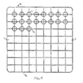
- a grid of the desired dimension is formed such as that grid G illustrated in Fig. 4.
- Two grids are formed.
- Tube member C is notched with respective transverse and longitudinal grooves 60, 61 at the top. Similar transverse and longitudinal grooves 60, 61 are notched at the bottom. It is into these respective notches that the identical top and bottom grids G1 and G2 are placed. At the end of such placement, a semirigid construction of tube members C and grids G1, G2 is formed as shown in Fig. 4 (only grid G1 there being shown in the partial plan view).
- the spacer at this stage forms a semi-rigid structure.
- the transverse and longitudinal grid members are interlocked by fitting into the respective notches. This interlocking feature holds the grid members in the correct positions.
- the grids in turn interlock with the tube members and hold them in their correct position.
- no jig is required to position the spacer parts for welding.
- the surrounding band segments N1, N2 are fastened as by welding to the grids, the particular band construction here shown including two band halves joined at 71, 72 typically by a butt weld.
- a drill bit D is shown removing excess material from the final tube member Cx. It will be understood that all excess material has been similarly removed from similar tube members.
- an upper grid G1 and a lower grid G2 are all interconnected by the tube members C.
- the butt welded and surrounding band N forms an integral spacer structure having a minimum of parasitic neutron absorbing material.
- FIG. 6 there is shown in plan view a spacer construction identical to that shown in Fig. 5. In this spacer construction a variable pitch is shown between contained fuel rods L.
- the fuel rods of Fig. 6 are arrayed in a 9x9 array.
- This 9x9 array includes eight groups of nine fuel rods each. The groups are designated E1 through E8.
- the fuel rods in each group are separated by a first and relatively narrow distance 80. In-between the respective groups the rod separation is greater.
- the rod separation between groups E3 and E4 is illustrated at 82. While it is not the purpose of this application to explain the theoretical nuclear efficiencies of such a fuel design, it can be seen the spacer construction technique and resulting spacer construction is capable of accommodating such a variable pitch.
- the band N can admit of modification. It will be seen that the band N includes upper flow diverting tabs 90, which tabs are known in the prior art.
- swirl vanes S include a continuous upper grid member 100.
- Continuous upper grid member forms an integral part of grid G1.
- the respective swirl vane members S all depend at sections 101, 102, 103 on one side of tube member C and at members 104, 105, etc. on the opposite side of cylinder C. These respective members are separated from one another by gaps 110.
- the swirl vane members 101-105 are each twisted 360° with respect to the upper and continuous grid member 100. Thereafter the respective members 101, 102, 103 are formed into a unitary and linear bottom grid member 120. This unitary grid member is appropriately notched at orthogonal notches 61 so that the resultant continuous grid member 120 mates with the lower grid G2. It can thus be seen that the disclosed swirl vane construction integrally participates in the formation of the upper and lower grids G1, G2. From the enclosed description it will be understood that this construction technique and spacer embodiment will admit of numerous modifications, such as twist angles of 270°, 180° and 90°.
Landscapes
- Physics & Mathematics (AREA)
- Engineering & Computer Science (AREA)
- Plasma & Fusion (AREA)
- General Engineering & Computer Science (AREA)
- High Energy & Nuclear Physics (AREA)
- Monitoring And Testing Of Nuclear Reactors (AREA)
- Filling Or Discharging Of Gas Storage Vessels (AREA)
- Physical Or Chemical Processes And Apparatus (AREA)
- Production Of Liquid Hydrocarbon Mixture For Refining Petroleum (AREA)
Applications Claiming Priority (2)
| Application Number | Priority Date | Filing Date | Title |
|---|---|---|---|
| US07/522,022 US5032351A (en) | 1990-05-11 | 1990-05-11 | Modified cross point spacer apparatus and construction |
| US522022 | 1990-05-11 |
Publications (2)
| Publication Number | Publication Date |
|---|---|
| EP0456055A1 true EP0456055A1 (fr) | 1991-11-13 |
| EP0456055B1 EP0456055B1 (fr) | 1995-12-13 |
Family
ID=24079118
Family Applications (1)
| Application Number | Title | Priority Date | Filing Date |
|---|---|---|---|
| EP91106808A Expired - Lifetime EP0456055B1 (fr) | 1990-05-11 | 1991-04-26 | Dispositif d'espacement croisé modifié et sa construction |
Country Status (7)
| Country | Link |
|---|---|
| US (1) | US5032351A (fr) |
| EP (1) | EP0456055B1 (fr) |
| JP (1) | JP2524014B2 (fr) |
| DE (1) | DE69115345T2 (fr) |
| DK (1) | DK0456055T3 (fr) |
| ES (1) | ES2081385T3 (fr) |
| NO (1) | NO911818L (fr) |
Cited By (3)
| Publication number | Priority date | Publication date | Assignee | Title |
|---|---|---|---|---|
| EP0555081A1 (fr) * | 1992-02-07 | 1993-08-11 | General Electric Company | Dispositif d'écartement comprenant un séparateur de vapeur |
| WO1994020962A1 (fr) * | 1993-03-08 | 1994-09-15 | Combustion Engineering, Inc. | Grille d'espcacement melangeuse en zircaloy destinee a des applications dans des reacteurs a eau sous pression et des reacteurs a eau bouillante |
| DE10250740A1 (de) * | 2002-10-31 | 2004-04-22 | Framatome Anp Gmbh | Brennelement für einen Siedewasserreaktor |
Families Citing this family (32)
| Publication number | Priority date | Publication date | Assignee | Title |
|---|---|---|---|---|
| US5229068A (en) * | 1991-05-17 | 1993-07-20 | General Electric Company | Optimized critical power in a fuel bundle with part length rods |
| US5186891A (en) * | 1991-05-17 | 1993-02-16 | General Electric Company | Swirl vanes in inconel spacer |
| US5209897A (en) * | 1992-02-18 | 1993-05-11 | General Electric Company | BWR core assembly |
| US5371768A (en) * | 1992-12-14 | 1994-12-06 | General Electric Company | Swirl type spacer for boiling water reactor fuel |
| US5361288A (en) * | 1993-08-16 | 1994-11-01 | General Electric Company | Spacer with integral zircaloy springs |
| US5434898A (en) * | 1994-03-14 | 1995-07-18 | Siemens Power Corporation | Nuclear fuel assembly |
| US5488644A (en) | 1994-07-13 | 1996-01-30 | General Electric Company | Spring assemblies for adjoining nuclear fuel rod containing ferrules and a spacer formed of the spring assemblies and ferrules |
| US5519747A (en) | 1994-10-04 | 1996-05-21 | General Electric Company | Apparatus and methods for fabricating spacers for a nuclear fuel rod bundle |
| US5546437A (en) | 1995-01-11 | 1996-08-13 | General Electric Company | Spacer for nuclear fuel rods |
| US5566217A (en) | 1995-01-30 | 1996-10-15 | General Electric Company | Reduced height spacer for nuclear fuel rods |
| US5572560A (en) * | 1995-06-29 | 1996-11-05 | Siemens Power Corporation | BWR fuel assembly having fuel rods with variable fuel rod pitches |
| US5675621A (en) | 1995-08-17 | 1997-10-07 | General Electric Company | Reduced height flat spring spacer for nuclear fuel rods |
| RU2120671C1 (ru) * | 1997-05-23 | 1998-10-20 | Государственный научный центр Российской Федерации | Дистанционирующая решетка для тепловыделяющей сборки ядерного реактора |
| US5859887A (en) * | 1997-06-20 | 1999-01-12 | Westinghouse Electric Company | Nuclear fuel assembly support grid |
| US6060016A (en) | 1998-11-11 | 2000-05-09 | Camco International, Inc. | Pneumatic isostatic forging of sintered compacts |
| RU2290707C1 (ru) * | 2005-07-08 | 2006-12-27 | Открытое акционерное общество "ТВЭЛ" | Дистанционирующая решетка |
| RU2331119C1 (ru) * | 2006-12-22 | 2008-08-10 | Открытое акционерное общество "ТВЭЛ" | Тепловыделяющая сборка и вставной дистанционирующий элемент |
| KR100900917B1 (ko) * | 2007-07-23 | 2009-06-03 | 한국원자력연구원 | 교차점 지지체를 이용한 이중냉각 핵연료봉의 지지격자체 |
| JP5038050B2 (ja) * | 2007-08-01 | 2012-10-03 | 白川 利久 | 原子炉の核燃料集合体におけるスペーサ |
| US20090135989A1 (en) * | 2007-11-28 | 2009-05-28 | Ge-Hitachi Nuclear Energy Americas Llc | Segmented fuel rod bundle designs using fixed spacer plates |
| UA98370C2 (ru) | 2007-12-26 | 2012-05-10 | Ториум Пауэр Инк. | Ядерный реактор (варианты), топливная сборка из зажигающе-воспроизводящих модулей для ядерного реактора (варианты) и топливный элемент топливной сборки |
| US8116423B2 (en) | 2007-12-26 | 2012-02-14 | Thorium Power, Inc. | Nuclear reactor (alternatives), fuel assembly of seed-blanket subassemblies for nuclear reactor (alternatives), and fuel element for fuel assembly |
| US8483349B2 (en) * | 2008-07-29 | 2013-07-09 | Korea Atomic Energy Research Institute | Spacer grid for dual-cooling nuclear fuel rods using intersectional support structures |
| RU2399968C2 (ru) * | 2008-10-20 | 2010-09-20 | Открытое акционерное общество "Опытное Конструкторское Бюро Машиностроения имени И.И. Африкантова" (ОАО "ОКБМ Африкантов") | Дистанционирующая решетка для тепловыделяющей сборки ядерного реактора |
| JP5755568B2 (ja) | 2008-12-25 | 2015-07-29 | トリウム・パワー、インクThorium Power,Inc. | 軽水炉核燃料集合体および軽水炉 |
| US10170207B2 (en) | 2013-05-10 | 2019-01-01 | Thorium Power, Inc. | Fuel assembly |
| WO2011143172A1 (fr) | 2010-05-11 | 2011-11-17 | Thorium Power, Inc. | Assemblage de combustible à noyau d'alliage de combustibles métalliques et son procédé de fabrication |
| US10192644B2 (en) | 2010-05-11 | 2019-01-29 | Lightbridge Corporation | Fuel assembly |
| EP2525364A1 (fr) * | 2011-05-20 | 2012-11-21 | Areva NP | Ensemble de combustible nucléaire doté d'un espacement variable entre les barres de combustible |
| CN102270511A (zh) * | 2011-07-18 | 2011-12-07 | 中国原子能科学研究院 | 一种压水堆双面冷却燃料棒的管形定位格架 |
| CN110828000B (zh) * | 2019-10-18 | 2021-11-09 | 广东核电合营有限公司 | 防异物格栅、下管座组件及燃料组件 |
| CN111613351B (zh) * | 2020-06-04 | 2022-05-20 | 中国核动力研究设计院 | 一种抗应力疲劳的压水堆燃料组件单金属定位栅格 |
Citations (4)
| Publication number | Priority date | Publication date | Assignee | Title |
|---|---|---|---|---|
| GB1094851A (en) * | 1964-01-16 | 1967-12-13 | Atomic Energy Authority Uk | Improvements in or relating to grids for nuclear fuel elements |
| DE1564434A1 (de) * | 1966-08-25 | 1970-01-22 | Nukem Gmbh | Abstandshalter fuer Brennelemente mit einer Vielzahl von Brennstoffstaeben |
| DE2203662A1 (de) * | 1972-01-27 | 1973-08-02 | Siemens Ag | Anlegeelement fuer in einem abstandshalter angeordnete brennstaebe von kernreaktoren |
| EP0308701A1 (fr) * | 1987-09-24 | 1989-03-29 | General Electric Company | Grille d'écartement avec tôle de guidage intégrée pour la formation de tourbillons |
Family Cites Families (7)
| Publication number | Priority date | Publication date | Assignee | Title |
|---|---|---|---|---|
| US3382153A (en) * | 1966-01-17 | 1968-05-07 | Gen Electric | Nuclear reactor fuel bundle |
| FR1539837A (fr) * | 1967-07-31 | 1968-09-20 | Alcatel S A Soc | Procédé de suppression des vibrations dans les tubes et dispositif anti vibratoiremettant en oeuvre ce procédé |
| US3966550A (en) * | 1971-03-18 | 1976-06-29 | Atlantic Richfield Company | Reactor fuel assemblies |
| US4059484A (en) * | 1975-05-02 | 1977-11-22 | Exxon Nuclear Company, Inc. | Hybrid nuclear fuel assembly with reduced linear heat generation rates |
| US4125435A (en) * | 1977-02-25 | 1978-11-14 | The Babcock & Wilcox Company | Grid lattice with sliding strap |
| US4708845A (en) * | 1985-10-18 | 1987-11-24 | Westinghouse Electric Corp. | BWR fuel assembly with improved spacer and fuel bundle design for enhanced thermal-hydraulic performance |
| FR2616577B1 (fr) * | 1987-06-09 | 1991-02-15 | Framatome Sa | Grille-entretoise pour un assemblage combustible d'un reacteur nucleaire a eau legere |
-
1990
- 1990-05-11 US US07/522,022 patent/US5032351A/en not_active Expired - Fee Related
-
1991
- 1991-04-26 ES ES91106808T patent/ES2081385T3/es not_active Expired - Lifetime
- 1991-04-26 DE DE69115345T patent/DE69115345T2/de not_active Expired - Fee Related
- 1991-04-26 EP EP91106808A patent/EP0456055B1/fr not_active Expired - Lifetime
- 1991-04-26 DK DK91106808.8T patent/DK0456055T3/da active
- 1991-05-07 JP JP3130329A patent/JP2524014B2/ja not_active Expired - Lifetime
- 1991-05-10 NO NO91911818A patent/NO911818L/no unknown
Patent Citations (4)
| Publication number | Priority date | Publication date | Assignee | Title |
|---|---|---|---|---|
| GB1094851A (en) * | 1964-01-16 | 1967-12-13 | Atomic Energy Authority Uk | Improvements in or relating to grids for nuclear fuel elements |
| DE1564434A1 (de) * | 1966-08-25 | 1970-01-22 | Nukem Gmbh | Abstandshalter fuer Brennelemente mit einer Vielzahl von Brennstoffstaeben |
| DE2203662A1 (de) * | 1972-01-27 | 1973-08-02 | Siemens Ag | Anlegeelement fuer in einem abstandshalter angeordnete brennstaebe von kernreaktoren |
| EP0308701A1 (fr) * | 1987-09-24 | 1989-03-29 | General Electric Company | Grille d'écartement avec tôle de guidage intégrée pour la formation de tourbillons |
Cited By (4)
| Publication number | Priority date | Publication date | Assignee | Title |
|---|---|---|---|---|
| EP0555081A1 (fr) * | 1992-02-07 | 1993-08-11 | General Electric Company | Dispositif d'écartement comprenant un séparateur de vapeur |
| US5327470A (en) * | 1992-02-07 | 1994-07-05 | General Electric Company | Spacer with steam separator |
| WO1994020962A1 (fr) * | 1993-03-08 | 1994-09-15 | Combustion Engineering, Inc. | Grille d'espcacement melangeuse en zircaloy destinee a des applications dans des reacteurs a eau sous pression et des reacteurs a eau bouillante |
| DE10250740A1 (de) * | 2002-10-31 | 2004-04-22 | Framatome Anp Gmbh | Brennelement für einen Siedewasserreaktor |
Also Published As
| Publication number | Publication date |
|---|---|
| JPH04231895A (ja) | 1992-08-20 |
| JP2524014B2 (ja) | 1996-08-14 |
| EP0456055B1 (fr) | 1995-12-13 |
| ES2081385T3 (es) | 1996-03-01 |
| NO911818D0 (no) | 1991-05-10 |
| DK0456055T3 (da) | 1996-01-29 |
| DE69115345T2 (de) | 1996-08-08 |
| US5032351A (en) | 1991-07-16 |
| NO911818L (no) | 1991-11-12 |
| DE69115345D1 (de) | 1996-01-25 |
Similar Documents
| Publication | Publication Date | Title |
|---|---|---|
| US5032351A (en) | Modified cross point spacer apparatus and construction | |
| EP0514120B1 (fr) | Ailettes de tourbillon dans une grille d'espacement en inconel | |
| EP0283836B1 (fr) | Enveloppe d'un assemblage de combustible à parois minces | |
| DE69115219T2 (de) | Zusammengesetzter Abstandshalter mit Inconel-Gitter und Zircaloy-Aussenband. | |
| EP0304724B1 (fr) | Grille d'espacement d'un assemblage de combustible nucléaire | |
| US5183629A (en) | Additional grid for a nuclear reactor fuel assembly, and assembly comprising an application thereof | |
| EP0291748B1 (fr) | Grille de support à ailettes mélangeuses | |
| EP0237064A2 (fr) | Grille de mélange pour un assemblace combustible de réacteur nucleaire | |
| US6421407B1 (en) | Nuclear fuel spacer grid with dipper vanes | |
| US4913875A (en) | Swirl vanes integral with spacer grid | |
| US4357298A (en) | Nuclear fuel assembly space arrangement | |
| DE3325749A1 (de) | Abstandshalter fuer eine kernbrennstoffeinheit | |
| DE69301325T2 (de) | Abstandshalter mit niedrigem Druckverlust für Kernbrennstabbündel | |
| US5327470A (en) | Spacer with steam separator | |
| US5024810A (en) | Support grid with integral inclined waves | |
| EP0254096A2 (fr) | Réacteur à eau bouillante comportant une grille d'espacement de barres de combustible positionnée axialement | |
| CA2643845C (fr) | Faisceau de barres de combustible a defaillance nulle | |
| KR910001978B1 (ko) | 일체 베인을 가진 지지 그리드 | |
| EP0528621B1 (fr) | Grille d'espacement résistant aux hydrures formée de lames interverrouillées pour un assemblage combustible de réacteur nucléaire à eau bouillante | |
| US6229868B1 (en) | Nuclear fuel assembly | |
| JPS6122290A (ja) | 核燃料集合体スペ−サ | |
| EP0805461A1 (fr) | Un élément d'espacement d'un ensemble combustible d'un réacteur nucléaire et un ensemble combustible d'un réacteur nucléaire | |
| EP0308701B1 (fr) | Grille d'écartement avec tôle de guidage intégrée pour la formation de tourbillons | |
| US4725402A (en) | Welded nuclear fuel grid and method | |
| USRE34246E (en) | Thin walled channel |
Legal Events
| Date | Code | Title | Description |
|---|---|---|---|
| PUAI | Public reference made under article 153(3) epc to a published international application that has entered the european phase |
Free format text: ORIGINAL CODE: 0009012 |
|
| AK | Designated contracting states |
Kind code of ref document: A1 Designated state(s): CH DE DK ES IT LI SE |
|
| 17P | Request for examination filed |
Effective date: 19911227 |
|
| 17Q | First examination report despatched |
Effective date: 19931102 |
|
| GRAA | (expected) grant |
Free format text: ORIGINAL CODE: 0009210 |
|
| AK | Designated contracting states |
Kind code of ref document: B1 Designated state(s): CH DE DK ES IT LI SE |
|
| REF | Corresponds to: |
Ref document number: 69115345 Country of ref document: DE Date of ref document: 19960125 |
|
| REG | Reference to a national code |
Ref country code: DK Ref legal event code: T3 |
|
| REG | Reference to a national code |
Ref country code: CH Ref legal event code: NV Representative=s name: RITSCHER & SEIFERT PATENTANWAELTE VSP |
|
| REG | Reference to a national code |
Ref country code: ES Ref legal event code: FG2A Ref document number: 2081385 Country of ref document: ES Kind code of ref document: T3 |
|
| ITF | It: translation for a ep patent filed | ||
| PGFP | Annual fee paid to national office [announced via postgrant information from national office to epo] |
Ref country code: SE Payment date: 19960319 Year of fee payment: 6 |
|
| PGFP | Annual fee paid to national office [announced via postgrant information from national office to epo] |
Ref country code: DK Payment date: 19960320 Year of fee payment: 6 |
|
| PGFP | Annual fee paid to national office [announced via postgrant information from national office to epo] |
Ref country code: DE Payment date: 19960326 Year of fee payment: 6 Ref country code: CH Payment date: 19960326 Year of fee payment: 6 |
|
| PGFP | Annual fee paid to national office [announced via postgrant information from national office to epo] |
Ref country code: ES Payment date: 19960415 Year of fee payment: 6 |
|
| PLBE | No opposition filed within time limit |
Free format text: ORIGINAL CODE: 0009261 |
|
| STAA | Information on the status of an ep patent application or granted ep patent |
Free format text: STATUS: NO OPPOSITION FILED WITHIN TIME LIMIT |
|
| 26N | No opposition filed | ||
| PG25 | Lapsed in a contracting state [announced via postgrant information from national office to epo] |
Ref country code: DK Effective date: 19970426 |
|
| REG | Reference to a national code |
Ref country code: DK Ref legal event code: EBP |
|
| PG25 | Lapsed in a contracting state [announced via postgrant information from national office to epo] |
Ref country code: SE Effective date: 19970427 |
|
| PG25 | Lapsed in a contracting state [announced via postgrant information from national office to epo] |
Ref country code: ES Free format text: LAPSE BECAUSE OF NON-PAYMENT OF DUE FEES Effective date: 19970428 |
|
| PG25 | Lapsed in a contracting state [announced via postgrant information from national office to epo] |
Ref country code: LI Free format text: LAPSE BECAUSE OF NON-PAYMENT OF DUE FEES Effective date: 19970430 Ref country code: CH Free format text: LAPSE BECAUSE OF NON-PAYMENT OF DUE FEES Effective date: 19970430 |
|
| REG | Reference to a national code |
Ref country code: CH Ref legal event code: PL |
|
| PG25 | Lapsed in a contracting state [announced via postgrant information from national office to epo] |
Ref country code: DE Free format text: LAPSE BECAUSE OF NON-PAYMENT OF DUE FEES Effective date: 19980101 |
|
| EUG | Se: european patent has lapsed |
Ref document number: 91106808.8 |
|
| REG | Reference to a national code |
Ref country code: ES Ref legal event code: FD2A Effective date: 19990503 |
|
| PG25 | Lapsed in a contracting state [announced via postgrant information from national office to epo] |
Ref country code: IT Free format text: LAPSE BECAUSE OF NON-PAYMENT OF DUE FEES;WARNING: LAPSES OF ITALIAN PATENTS WITH EFFECTIVE DATE BEFORE 2007 MAY HAVE OCCURRED AT ANY TIME BEFORE 2007. THE CORRECT EFFECTIVE DATE MAY BE DIFFERENT FROM THE ONE RECORDED. Effective date: 20050426 |