EP0456082A1 - Palier à contact de roulement pour déplacement linéaire - Google Patents
Palier à contact de roulement pour déplacement linéaire Download PDFInfo
- Publication number
- EP0456082A1 EP0456082A1 EP91106968A EP91106968A EP0456082A1 EP 0456082 A1 EP0456082 A1 EP 0456082A1 EP 91106968 A EP91106968 A EP 91106968A EP 91106968 A EP91106968 A EP 91106968A EP 0456082 A1 EP0456082 A1 EP 0456082A1
- Authority
- EP
- European Patent Office
- Prior art keywords
- cage
- tracks
- ball bearing
- shaft
- slot
- Prior art date
- Legal status (The legal status is an assumption and is not a legal conclusion. Google has not performed a legal analysis and makes no representation as to the accuracy of the status listed.)
- Granted
Links
- 238000005096 rolling process Methods 0.000 title claims 2
- 238000005266 casting Methods 0.000 claims description 5
- 239000000463 material Substances 0.000 claims description 2
- 238000011161 development Methods 0.000 description 5
- 230000018109 developmental process Effects 0.000 description 5
- 238000007789 sealing Methods 0.000 description 4
- 238000006073 displacement reaction Methods 0.000 description 2
- 238000004519 manufacturing process Methods 0.000 description 2
- 238000000034 method Methods 0.000 description 2
- 230000035939 shock Effects 0.000 description 2
- 229910000831 Steel Inorganic materials 0.000 description 1
- 238000004026 adhesive bonding Methods 0.000 description 1
- 239000000919 ceramic Substances 0.000 description 1
- 229920001971 elastomer Polymers 0.000 description 1
- 239000000806 elastomer Substances 0.000 description 1
- 238000002347 injection Methods 0.000 description 1
- 239000007924 injection Substances 0.000 description 1
- 238000000465 moulding Methods 0.000 description 1
- 239000007921 spray Substances 0.000 description 1
- 238000009718 spray deposition Methods 0.000 description 1
- 239000010959 steel Substances 0.000 description 1
- 238000007740 vapor deposition Methods 0.000 description 1
- 238000003466 welding Methods 0.000 description 1
Images
Classifications
-
- F—MECHANICAL ENGINEERING; LIGHTING; HEATING; WEAPONS; BLASTING
- F16—ENGINEERING ELEMENTS AND UNITS; GENERAL MEASURES FOR PRODUCING AND MAINTAINING EFFECTIVE FUNCTIONING OF MACHINES OR INSTALLATIONS; THERMAL INSULATION IN GENERAL
- F16C—SHAFTS; FLEXIBLE SHAFTS; ELEMENTS OR CRANKSHAFT MECHANISMS; ROTARY BODIES OTHER THAN GEARING ELEMENTS; BEARINGS
- F16C29/00—Bearings for parts moving only linearly
- F16C29/04—Ball or roller bearings
- F16C29/06—Ball or roller bearings in which the rolling bodies circulate partly without carrying load
- F16C29/068—Ball or roller bearings in which the rolling bodies circulate partly without carrying load with the bearing body fully encircling the guide rail or track
- F16C29/0683—Ball or roller bearings in which the rolling bodies circulate partly without carrying load with the bearing body fully encircling the guide rail or track the bearing body encircles a rail or rod of circular cross-section, i.e. the linear bearing is not suited to transmit torque
- F16C29/0685—Ball or roller bearings in which the rolling bodies circulate partly without carrying load with the bearing body fully encircling the guide rail or track the bearing body encircles a rail or rod of circular cross-section, i.e. the linear bearing is not suited to transmit torque with balls
- F16C29/069—Ball or roller bearings in which the rolling bodies circulate partly without carrying load with the bearing body fully encircling the guide rail or track the bearing body encircles a rail or rod of circular cross-section, i.e. the linear bearing is not suited to transmit torque with balls whereby discrete load bearing elements, e.g. discrete load bearing plates or discrete rods, are provided in a retainer and form the load bearing tracks
-
- F—MECHANICAL ENGINEERING; LIGHTING; HEATING; WEAPONS; BLASTING
- F16—ENGINEERING ELEMENTS AND UNITS; GENERAL MEASURES FOR PRODUCING AND MAINTAINING EFFECTIVE FUNCTIONING OF MACHINES OR INSTALLATIONS; THERMAL INSULATION IN GENERAL
- F16C—SHAFTS; FLEXIBLE SHAFTS; ELEMENTS OR CRANKSHAFT MECHANISMS; ROTARY BODIES OTHER THAN GEARING ELEMENTS; BEARINGS
- F16C43/00—Assembling bearings
- F16C43/04—Assembling rolling-contact bearings
- F16C43/06—Placing rolling bodies in cages or bearings
- F16C43/08—Placing rolling bodies in cages or bearings by deforming the cages or the races
Definitions
- the present invention relates to a ball bearing for longitudinal movements according to the preamble of claim 1.
- a ball bearing of the type mentioned is known, in which the deflection paths of each row of balls are closed radially inwards towards the shaft by a ramp of the cage (DE-PS 27 25 355).
- the balls move along the guide and return paths and are lifted radially from the shaft on this starting ramp.
- the corresponding start-up movements and radial displacements of the balls cause shock forces in the ball bearing, which can result in undesired running noise from the ball bearing.
- the ramp of the ball bearing must be worked into the cage and the associated cover using complicated tools.
- the starting ramps of the known ball bearing are also relatively sensitive because of their thin walls.
- the invention characterized in claim 1 is based on the object to provide a ball bearing for longitudinal movements of the type mentioned, which runs extremely quietly, is robust and also can be manufactured particularly economically.
- the ball bearing for longitudinal movements of the invention it is achieved that the balls of each row, coming from the guideway or from the return path, run smoothly and noiselessly into the deflection path of the cover in question. Likewise, the balls of each row are guided from the relevant deflection path back into the subsequent guiding or return path without an abrupt radial displacement. In this way, the balls do not experience any shock during their movement in the ball bearing.
- the ball bearing of the invention accordingly has a particularly great smoothness and can have an advantageously small radial height.
- the curved shoulder sections in the bore of the cage and the corresponding curved wall sections of the cover in question can be economically incorporated into the ball bearing according to the invention by axial tools.
- the cage and the two associated lids can be given a shape that results in a relatively impact-resistant and robust design of the ball bearing.
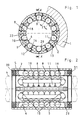
- FIG. 1 in FIG. 1 denotes a housing, in the cylindrical bore 2 of which a cage of a side-symmetrical ball bearing for longitudinal movements is installed.
- the cage 3 is sleeve-shaped so that it completely surrounds a cylindrical shaft 4 with an inner surface - see dash-dotted representations in FIGS. 1 and 2.
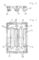
- annular cover 7 is fastened to the cage and sits on a cylindrical bore surface 6 of one end section 5 of the cage 3 (FIG. 2).
- the cage 3 has axial guideways 8 for loaded balls 9 and axial return paths 10 for unloaded balls 11.
- the cage 3 and its two covers 7 are made of an elastomer casting material, they are each injection molded in a mold (not shown).
- the casting mold of the cage can have axial slides for molding the guide tracks 8 and return tracks 10 of the cage 3 in a manner known per se.
- One guideway 8 and one return path 10 are alternately arranged on the circumference of the cage 3.
- a steel raceway element 12 is installed radially above each guideway 8 in the cage.
- Each raceway element 12 is snapped captively into a radially continuous opening 13 of the cage 3, it has an outer side which is radially supported in the bore of the housing 1 and an inner side which is provided with a longitudinally grooved raceway 14 for the loaded balls 9.
- the balls 9 roll between the raceway 14 of the relevant raceway element 12 and a cylindrical outer surface of the shaft 4 and thereby transfer a radial load from the shaft 4 via the raceway element 12 to the bore 2 of the housing 1.
- the two covers 7 have semicircular deflection tracks 15 arranged on their inner circumference and distributed around the circumference. Each deflection track 15 connects the end of a guide track 8 to the end of an adjacent return track 10. Each deflection track 15 is opened by a correspondingly semi-curved shoulder section 16 the inner surface of the cage 3 and delimits an opposing inner wall section 17 of the cover 7, which runs parallel to it and is curved.
- a guide path 8 In each case a guide path 8, a return path 10 and two end deflection paths 15 arranged axially opposite one another form a self-contained path in which an endless row of balls 9, 11 is installed.
- Each closed track of the ball bearing has a slot running along it, open towards the shaft 4, which is composed of an axially extending slot 18 of the guide track 8, a semicircular slot 19 of the two deflection tracks 15 and an axially extending slot 20 of the return track 10.
- the slot 19 of each deflection path 15 opens at its ends into the slot 8 of the adjoining guideway 8 or into the slot 20 of the adjoining return path 10.
- the radially inner slot width 21 of the slot 19 of the deflection tracks 15 is the same size as the inner slot width of the return tracks 10, it is sufficiently large that the unloaded balls 11 up to the shaft 4 protrude radially inward from the slot 19 and 20 and thus are guided radially on the shaft 4.
- the slot width 21 is incidentally somewhat smaller than the diameter of the balls 11.
- the radially inner slot width of the slot 18 of each guideway 8 is somewhat smaller than the diameter of the balls 9. In this way, the balls 9, 11 can radially inward from the ball bearing do not fall out when the shaft 4 is pulled out of the ball bearing and removed.
- the deflection tracks 15 of the two covers 7 have lateral guide walls formed by the shoulder section 16 and the wall section 17, one of the balls 11 in part have extensive, substantially circular section-shaped cross-sectional contour.
- the axially extending guide and return paths 8 and 10 have lateral guide walls which have a cross-sectional contour which is substantially circular and partially encompasses the balls 9 and 11, respectively.
- the guide and return paths 8, 10 and the deflection paths 15 have cross-sectional centers which are arranged lying on a common cylinder 22 which is concentric with the axis of the shaft 4.
- the bore surface 6 of each end section 5 of the cage 3 covers the deflection paths 15 of the cover 7 in question radially from the outside.
- Each cover 7 has a jacket surface 23 seated on the bore surface 6, which is provided with retaining lugs 24 arranged on the circumference and projecting radially outward beyond the jacket surface 23.
- the retaining lugs 24 are snapped into corresponding, radially continuous recesses 25 of the bore surface 6 of the cage 3 and engage in a form-fitting manner (FIGS. 3 and 4).
- each cover 7 has axially inwardly facing flat end surface sections 26.
- one end surface section 26 is integrally formed on the cover 7 between two deflection paths 15 adjacent on the circumference. All end surface sections 26 of the cover 7 are arranged so as to lie firmly against a flat support surface section 27 of the cage 3 opposite this.
- each support surface section 27 has an axial peg-shaped projection 28 which engages in a round hole recess 29 in the associated end surface section 26 (FIGS. 3 and 4).
- a sealing ring 30 is used at the left end of the cage 3, which with the Shell surface of the shaft 4 forms a narrow sealing gap.
- the cage 3 has a sealing ring 31, the sealing lips of which slide on the lateral surface of the shaft 4 in the longitudinal direction.
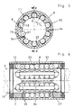
- FIGs 5 and 6 a modified ball bearing for longitudinal movements is shown, which is constructed similarly to the ball bearing described above, because this also has axial guide and return paths 8 and 10 of a cage 3 and semicircular deflection paths 15 of two end covers 7. Die Tracks 8, 10 and 15 also have a slot 18, 19 and 20 open towards shaft 4.
- each raceway element is formed by a ceramic or metallic layer 32 on a radially outer wall section 33, the guide track 8 of the cage 3 section-shaped in cross-sectional circle.
- a spray or vapor deposition method (plasma jet method) can be used to apply the layer 32.
- the cage 3 has two end covers 7, the flat end face sections of which are each on a flat support surface section 27 of the cage 3, for. B. are permanently attached by gluing or ultrasonic welding.
- the cage 3 In its bore, the cage 3 has radial incisions 34 formed in the casting process with axial slides (not shown), which pass through two axially opposing supporting surface sections 27 of the cage 3. Each incision 34 is open radially inwards, towards the shaft 4, and is closed radially outwards. At one or both ends of at least one incision 34, an axial projection 35 of a supporting surface portion 27 of the relevant cover 7, which extends at most up to the end face section of the axially opposite cover 7, engages in the incision 34 in a form-fitting manner.
- Each incision 34 runs in the immediate vicinity of one of the return paths 10 of the cage 3, so that between the return path 10 and the incision 34 a thin-walled, flexible cage portion 36 is formed.
- each ball can be inserted into the bore of the cage 3, pressed radially outward from there and snapped into the return path 10 (see ball 37 in FIG. 5).
- the cage section 36 is bent somewhat elastically aside in the circumferential direction, so that the inner width 21 of the slot 20 increases briefly.
- the cage also need not be designed as a sleeve which is closed on the circumference. Rather, the cage and the associated cover can also have a common slot extending in the longitudinal direction, so that the inner surface of the cage only partially surrounds the shaft. Support elements of a foundation or the like can then engage in this slot, which are non-positively connected to the shaft and support it on the foundation.
Landscapes
- Engineering & Computer Science (AREA)
- General Engineering & Computer Science (AREA)
- Mechanical Engineering (AREA)
- Bearings For Parts Moving Linearly (AREA)
- Rolling Contact Bearings (AREA)
Applications Claiming Priority (2)
| Application Number | Priority Date | Filing Date | Title |
|---|---|---|---|
| DE4015124A DE4015124A1 (de) | 1990-05-11 | 1990-05-11 | Kugellager fuer laengsbewegungen |
| DE4015124 | 1990-05-11 |
Publications (2)
| Publication Number | Publication Date |
|---|---|
| EP0456082A1 true EP0456082A1 (fr) | 1991-11-13 |
| EP0456082B1 EP0456082B1 (fr) | 1993-12-22 |
Family
ID=6406175
Family Applications (1)
| Application Number | Title | Priority Date | Filing Date |
|---|---|---|---|
| EP91106968A Expired - Lifetime EP0456082B1 (fr) | 1990-05-11 | 1991-04-30 | Palier à contact de roulement pour déplacement linéaire |
Country Status (4)
| Country | Link |
|---|---|
| US (1) | US5145260A (fr) |
| EP (1) | EP0456082B1 (fr) |
| JP (1) | JP2859463B2 (fr) |
| DE (2) | DE4015124A1 (fr) |
Cited By (5)
| Publication number | Priority date | Publication date | Assignee | Title |
|---|---|---|---|---|
| FR2759432A1 (fr) * | 1997-02-07 | 1998-08-14 | Skf Linearsysteme Gmbh | Roulement a billes pour mouvements longitudinaux et son procede de fabrication |
| EP1970582A2 (fr) | 2007-03-16 | 2008-09-17 | Ab Skf | Joint dans un roulement linéaire |
| EP1970583A2 (fr) | 2007-03-16 | 2008-09-17 | Ab Skf | Palier à roulement linéaire |
| EP1970584A3 (fr) * | 2007-03-16 | 2012-04-25 | Ab Skf | Palier à roulement linéaire |
| EP1970581A3 (fr) * | 2007-03-16 | 2012-04-25 | Ab Skf | Palier à roulement linéaire |
Families Citing this family (12)
| Publication number | Priority date | Publication date | Assignee | Title |
|---|---|---|---|---|
| US5221145A (en) * | 1992-01-17 | 1993-06-22 | Rmb Roulements Miniatures | Linear bearing |
| DE4223499C2 (de) * | 1992-07-17 | 2002-02-21 | Schaeffler Waelzlager Ohg | Wälzlager für eine geradlinige Bewegung |
| US5558442A (en) * | 1993-07-20 | 1996-09-24 | Thomson Industries, Inc. | Linear motion bearing assembly |
| DE19704630C2 (de) * | 1997-02-07 | 1999-08-12 | Skf Linearsysteme Gmbh | Radial-Dichtung |
| DE19704633C1 (de) * | 1997-02-07 | 1998-07-09 | Skf Linearsysteme Gmbh | Kugellager für Längsbewegungen |
| DE19741626B4 (de) * | 1997-09-20 | 2008-03-27 | Skf Linearsysteme Gmbh | Kugellager für Längsbewegungen |
| JP2003004040A (ja) * | 2001-06-19 | 2003-01-08 | Thk Co Ltd | 転がり案内装置 |
| DE102005054516B3 (de) * | 2005-11-16 | 2007-03-22 | Aktiebolaget Skf | Linearlager |
| US8998490B2 (en) | 2010-08-11 | 2015-04-07 | Thomson Industries, Inc. | Clam shell linear motion bearing assembly |
| DE102011017757B4 (de) * | 2011-04-29 | 2014-11-27 | Aktiebolaget Skf | Konzept zum Abdichten einer Linearführung |
| JP5695248B2 (ja) | 2013-04-10 | 2015-04-01 | Thk株式会社 | 運動案内装置 |
| JP7319023B2 (ja) * | 2019-03-07 | 2023-08-01 | Thk株式会社 | ボールスプライン |
Citations (3)
| Publication number | Priority date | Publication date | Assignee | Title |
|---|---|---|---|---|
| CH519118A (fr) * | 1970-01-22 | 1972-02-15 | Roulements Miniatures S A | Roulement à billes pour le montage d'arbres mobiles longitudinalement |
| FR2384155A2 (fr) * | 1977-03-18 | 1978-10-13 | Skf Kugellagerfabriken Gmbh | Douille a billes |
| DE2725355C2 (de) * | 1977-06-04 | 1984-04-12 | Skf Kugellagerfabriken Gmbh, 8720 Schweinfurt | Kugelbüchse |
Family Cites Families (3)
| Publication number | Priority date | Publication date | Assignee | Title |
|---|---|---|---|---|
| DE3207516A1 (de) * | 1982-03-03 | 1983-09-08 | Skf Kugellagerfabriken Gmbh | Waelzlager fuer laengsbewegungen |
| US4469380A (en) * | 1982-05-19 | 1984-09-04 | The Torrington Company | Linear movement anti-friction bearing |
| DE3937781A1 (de) * | 1989-04-08 | 1990-10-11 | Werner Dipl Ing Jacob | Kugelumlaufeinheit fuer eine linearkugelfuehrung |
-
1990
- 1990-05-11 DE DE4015124A patent/DE4015124A1/de not_active Withdrawn
-
1991
- 1991-04-30 EP EP91106968A patent/EP0456082B1/fr not_active Expired - Lifetime
- 1991-04-30 DE DE91106968T patent/DE59100745D1/de not_active Expired - Lifetime
- 1991-05-09 JP JP3132191A patent/JP2859463B2/ja not_active Expired - Lifetime
- 1991-05-10 US US07/698,662 patent/US5145260A/en not_active Expired - Lifetime
Patent Citations (3)
| Publication number | Priority date | Publication date | Assignee | Title |
|---|---|---|---|---|
| CH519118A (fr) * | 1970-01-22 | 1972-02-15 | Roulements Miniatures S A | Roulement à billes pour le montage d'arbres mobiles longitudinalement |
| FR2384155A2 (fr) * | 1977-03-18 | 1978-10-13 | Skf Kugellagerfabriken Gmbh | Douille a billes |
| DE2725355C2 (de) * | 1977-06-04 | 1984-04-12 | Skf Kugellagerfabriken Gmbh, 8720 Schweinfurt | Kugelbüchse |
Cited By (7)
| Publication number | Priority date | Publication date | Assignee | Title |
|---|---|---|---|---|
| FR2759432A1 (fr) * | 1997-02-07 | 1998-08-14 | Skf Linearsysteme Gmbh | Roulement a billes pour mouvements longitudinaux et son procede de fabrication |
| EP1970582A2 (fr) | 2007-03-16 | 2008-09-17 | Ab Skf | Joint dans un roulement linéaire |
| EP1970583A2 (fr) | 2007-03-16 | 2008-09-17 | Ab Skf | Palier à roulement linéaire |
| EP1970582A3 (fr) * | 2007-03-16 | 2012-04-25 | Ab Skf | Joint dans un roulement linéaire |
| EP1970584A3 (fr) * | 2007-03-16 | 2012-04-25 | Ab Skf | Palier à roulement linéaire |
| EP1970581A3 (fr) * | 2007-03-16 | 2012-04-25 | Ab Skf | Palier à roulement linéaire |
| EP1970583A3 (fr) * | 2007-03-16 | 2012-08-22 | Ab Skf | Palier à roulement linéaire |
Also Published As
| Publication number | Publication date |
|---|---|
| DE4015124A1 (de) | 1991-11-14 |
| US5145260A (en) | 1992-09-08 |
| JPH04228917A (ja) | 1992-08-18 |
| EP0456082B1 (fr) | 1993-12-22 |
| JP2859463B2 (ja) | 1999-02-17 |
| DE59100745D1 (de) | 1994-02-03 |
Similar Documents
| Publication | Publication Date | Title |
|---|---|---|
| EP0456082B1 (fr) | Palier à contact de roulement pour déplacement linéaire | |
| DE3841629C2 (de) | Rollenlagerung | |
| DE69801874T2 (de) | Körper zum Verbinden von Kugeln und diesen verwendende Kugelgewindeeinrichtung | |
| EP1200749B1 (fr) | Palier a billes lineaire | |
| DE2711882C2 (de) | Kugelbüchse | |
| DE2909508A1 (de) | Waelzlager fuer laengsbewegungen | |
| DE2649245A1 (de) | Kugellager fuer laengsbewegungen | |
| DE7911040U1 (de) | Waelzlager fuer laengsbewegungen | |
| DE69200363T3 (de) | Rollenkäfig. | |
| DE3041804A1 (de) | Waelzlager fuer die laengsfuehrung einer welle o.dgl. | |
| EP0210650B1 (fr) | Electro-aimant | |
| DE3512013C2 (fr) | ||
| DE19646310A1 (de) | Radial-Wälzlager | |
| DE1575608B2 (de) | Wälzlager für Längsbewegungen | |
| DE3142047A1 (de) | Vorrichtung zum druckgiessen eines waelzlagerkaefigs | |
| DE2631808C2 (de) | Kugelbüchse für Längsführungen | |
| DE3326601A1 (de) | Kugellager fuer laengsbewegungen | |
| DE69110789T2 (de) | Linearführung. | |
| DE19704632C1 (de) | Kugellager für Längsbewegungen und Verfahren zu seiner Herstellung | |
| DE2019506B2 (de) | Kugellager für axiale Bewegungen bezüglich einer Welle | |
| DE2832744C2 (de) | Kugelbüchse | |
| EP2789867B1 (fr) | Canal de guidage à billes d'un guidage linéaire à palier à billes | |
| DE3902937C2 (de) | Changierlager | |
| DE3533403A1 (de) | Waelzlager fuer laengsbewegungen | |
| DE4031337A1 (de) | Kaefig zur schaffung eines selbsthaltenden waelzlagers |
Legal Events
| Date | Code | Title | Description |
|---|---|---|---|
| PUAI | Public reference made under article 153(3) epc to a published international application that has entered the european phase |
Free format text: ORIGINAL CODE: 0009012 |
|
| AK | Designated contracting states |
Kind code of ref document: A1 Designated state(s): CH DE FR GB IT LI SE |
|
| 17P | Request for examination filed |
Effective date: 19911125 |
|
| 17Q | First examination report despatched |
Effective date: 19930512 |
|
| GRAA | (expected) grant |
Free format text: ORIGINAL CODE: 0009210 |
|
| AK | Designated contracting states |
Kind code of ref document: B1 Designated state(s): CH DE FR GB IT LI SE |
|
| PG25 | Lapsed in a contracting state [announced via postgrant information from national office to epo] |
Ref country code: IT Free format text: LAPSE BECAUSE OF FAILURE TO SUBMIT A TRANSLATION OF THE DESCRIPTION OR TO PAY THE FEE WITHIN THE PRE;WARNING: LAPSES OF ITALIAN PATENTS WITH EFFECTIVE DATE BEFORE 2007 MAY HAVE OCCURRED AT ANY TIME BEFORE 2007. THE CORRECT EFFECTIVE DATE MAY BE DIFFERENT FROM THE ONE RECORDED.SCRIBED TIME-LIMIT Effective date: 19931222 Ref country code: SE Effective date: 19931222 |
|
| REF | Corresponds to: |
Ref document number: 59100745 Country of ref document: DE Date of ref document: 19940203 |
|
| PGFP | Annual fee paid to national office [announced via postgrant information from national office to epo] |
Ref country code: SE Payment date: 19940415 Year of fee payment: 4 |
|
| GBT | Gb: translation of ep patent filed (gb section 77(6)(a)/1977) |
Effective date: 19940324 |
|
| ET | Fr: translation filed | ||
| PLBE | No opposition filed within time limit |
Free format text: ORIGINAL CODE: 0009261 |
|
| STAA | Information on the status of an ep patent application or granted ep patent |
Free format text: STATUS: NO OPPOSITION FILED WITHIN TIME LIMIT |
|
| 26N | No opposition filed | ||
| REG | Reference to a national code |
Ref country code: GB Ref legal event code: IF02 |
|
| PGFP | Annual fee paid to national office [announced via postgrant information from national office to epo] |
Ref country code: FR Payment date: 20100506 Year of fee payment: 20 |
|
| PGFP | Annual fee paid to national office [announced via postgrant information from national office to epo] |
Ref country code: DE Payment date: 20100428 Year of fee payment: 20 |
|
| PGFP | Annual fee paid to national office [announced via postgrant information from national office to epo] |
Ref country code: CH Payment date: 20100426 Year of fee payment: 20 |
|
| PGFP | Annual fee paid to national office [announced via postgrant information from national office to epo] |
Ref country code: GB Payment date: 20100426 Year of fee payment: 20 |
|
| REG | Reference to a national code |
Ref country code: DE Ref legal event code: R071 Ref document number: 59100745 Country of ref document: DE |
|
| REG | Reference to a national code |
Ref country code: CH Ref legal event code: PL |
|
| REG | Reference to a national code |
Ref country code: GB Ref legal event code: PE20 Expiry date: 20110429 |
|
| PG25 | Lapsed in a contracting state [announced via postgrant information from national office to epo] |
Ref country code: GB Free format text: LAPSE BECAUSE OF EXPIRATION OF PROTECTION Effective date: 20110429 |
|
| PG25 | Lapsed in a contracting state [announced via postgrant information from national office to epo] |
Ref country code: DE Free format text: LAPSE BECAUSE OF EXPIRATION OF PROTECTION Effective date: 20110430 |