EP0456104A1 - Stützprofil für ein Ladenbausystem oder dergleichen - Google Patents
Stützprofil für ein Ladenbausystem oder dergleichen Download PDFInfo
- Publication number
- EP0456104A1 EP0456104A1 EP91107063A EP91107063A EP0456104A1 EP 0456104 A1 EP0456104 A1 EP 0456104A1 EP 91107063 A EP91107063 A EP 91107063A EP 91107063 A EP91107063 A EP 91107063A EP 0456104 A1 EP0456104 A1 EP 0456104A1
- Authority
- EP
- European Patent Office
- Prior art keywords
- symmetry
- plane
- profile
- receiving
- support profile
- Prior art date
- Legal status (The legal status is an assumption and is not a legal conclusion. Google has not performed a legal analysis and makes no representation as to the accuracy of the status listed.)
- Granted
Links
- 230000000295 complement effect Effects 0.000 claims abstract description 5
- 238000010276 construction Methods 0.000 abstract description 7
- 210000001331 nose Anatomy 0.000 abstract 1
- 239000000463 material Substances 0.000 description 3
- 238000005286 illumination Methods 0.000 description 2
- 239000012634 fragment Substances 0.000 description 1
- 238000000034 method Methods 0.000 description 1
- 238000005192 partition Methods 0.000 description 1
- 238000004381 surface treatment Methods 0.000 description 1
Images


Classifications
-
- A—HUMAN NECESSITIES
- A47—FURNITURE; DOMESTIC ARTICLES OR APPLIANCES; COFFEE MILLS; SPICE MILLS; SUCTION CLEANERS IN GENERAL
- A47B—TABLES; DESKS; OFFICE FURNITURE; CABINETS; DRAWERS; GENERAL DETAILS OF FURNITURE
- A47B96/00—Details of cabinets, racks or shelf units not covered by a single one of groups A47B43/00 - A47B95/00; General details of furniture
- A47B96/14—Bars, uprights, struts, or like supports, for cabinets, brackets, or the like
- A47B96/1416—Uprights receiving panels and brackets
-
- A—HUMAN NECESSITIES
- A47—FURNITURE; DOMESTIC ARTICLES OR APPLIANCES; COFFEE MILLS; SPICE MILLS; SUCTION CLEANERS IN GENERAL
- A47F—SPECIAL FURNITURE, FITTINGS, OR ACCESSORIES FOR SHOPS, STOREHOUSES, BARS, RESTAURANTS OR THE LIKE; PAYING COUNTERS
- A47F5/00—Show stands, hangers, or shelves characterised by their constructional features
- A47F5/10—Adjustable or foldable or dismountable display stands
Definitions
- the present invention relates to a support profile for building a shop fitting system or the like.
- shopfitting systems, shelving systems, display systems ... we encounter them in many different ways.
- the quality and practicability of such a shop fitting system for example, with regard to the task, both with regard to the intended use as a means of presentation, and with regard to the appearance, i.e. the aesthetic advertising effectiveness, is determined to a large extent by the design freedom of the user.
- a high-quality shop fitting system can be recognized by how much design freedom is available to the user and what kind of design freedom this is.
- the object on which the present invention is based is to specify a support profile for the construction of shop fitting systems or similar presentation systems which can be built up in a modular manner and which permits optimum variability.
- the presentation system to be constructed with the support profile according to the invention should in particular also be easily and easily assembled and disassembled.
- an essentially U-shaped profile rail is provided which a) mirror-symmetrically to the plane of symmetry of the U on the outer sides of the side walls lying parallel to one another, a plurality of guide grooves oriented parallel or perpendicular to the plane of symmetry for receiving parallel or perpendicular wall elements oriented to the plane of symmetry is provided, and that b) on the base side of the U, laterally outwardly directed profile lugs are designed to engage a front profile provided with complementary locking grooves.
- This provides a basic profile that can be used as a construction and front element for shop fitting systems, and can be veneered with a front profile of any shape and color, and that also serves as a hub for a changeable and expandable wall system.
- Fig. 1 shows the basic elements of a shopfitting system, namely the core of the present invention, the support profile 1 in cross section.
- the basic geometric shape of this support profile 1 is determined by a U-shaped profile rail 2, the side walls 3 of which are constructed in a very specific manner, specifically as follows:
- the free end faces of the side walls 3 are configured as rectangular (first) guide grooves 4, the lines of symmetry of which run parallel to the plane of symmetry S of the profile rail 2.
- the first guide grooves 4 thus form an open channel, into which - see FIG. 5 - a wall element oriented parallel to the side wall 3 can be inserted.
- a T-shaped channel 5 adjoins these first guide grooves 4, the outer boundaries of which lie parallel to the side walls 3 and are aligned with the outer sides of the first guide grooves 4.
- This T-shaped channel 5 serves - see Fig. 4 - for receiving along the T-shaped channel 5 continuously adjustable shelf supports for shelves or similar shelves.
- the T-shaped channel 5 is followed by a (second) guide groove 6, the line of symmetry of which runs perpendicular to the plane of symmetry S of the U-shaped profile rail 2. Wall elements perpendicular to the plane of symmetry S can be inserted into these second guide grooves 6 - see FIG. 5.
- the base side of the U-shaped profile rail 2 has a protrusion 8 on each side, onto which profile lugs 9 oriented at a distance from the side walls 3 in the direction away from the base side 7 are worked on.
- these profile lugs 9 are designed as follows: the protrusion 8 begins at a distance from the base side 7 and forms one side of the second guide grooves 6 mentioned.
- the protrusion 8 In the through the T-shaped channel 5 and the first guide groove 4 Defined, parallel to the side wall 3 level adjoins the projection 8 a (third) guide groove 10, the base of which is in the plane of the base 7 of the profile rail 2, and on the free wall of the profile nose 9 is formed as a protruding longitudinal web 11.
- the free end face of the wall mentioned has a shoulder 12 which is oriented toward the profile rail 2.
- the removed from the rail 2, in the plane of the base 7 corner of the third guide groove 10 is chamfered, in such a way that this bevel 13 itself is part of the profile lugs 9 in that the bevel 13 merges into an undercut, which ultimately the longitudinal web 11 forms.
- the support profile 1 described so far fulfills the basic tasks, namely - to accommodate a front profile 17 via the profile lugs 9, - to lock wall elements via the guide grooves 4, 6, 10 and - via the T-shaped channels 5 - shelves or the like hold.
- the profile rail 2 has two mounting webs 14, which are directed towards one another and by means of which — compare FIG. 7 — a lamp or the like can be integrated.
- On the free end faces of the U-shaped profile rail 2 there are furthermore webs 15 directed towards the plane of symmetry S, which serve as a (receiving) catch for a cover rail 16 that can be fitted.
- This cover rail 16 consists of a flat material, which laterally has undercuts corresponding to the webs 15, via which the cover rail 16 can be clipped onto the profile rail 2 (see arrow X).
- the profile lugs 9 mentioned serve for the clamping of a front profile 17, which is formed here in FIG. 1 as a triangular molded part.
- This triangular molded part has on the two free triangle sides a pair of conjugated projections 18, 19, which together define a locking groove 20.
- This locking groove 20 is in this respect exactly complementary to the profile nose 9 worked on the U-shaped profile rail 2 in such a way that the front profile 17 can be spring-loaded onto the base side 7 of the profile rail 2 (compare arrow Y).
- the front profile 17 is thus clipped onto the support profile 1 in a positive and non-positive manner by simply plugging it on, and forms a shapely finish for this support profile 1.
- FIG. 2 shows an assembly unit assembled from a support profile 1 and a front profile 17.
- the simple assembly or attachment process of the front profiles 17 to a shopfitting system assembled from support profiles 1 ultimately enables exceptional variability.
- the front profiles 17 can be designed not only with regard to the choice of material and color as such, as well as the surface treatment, but also with regard to the shape of the veneer.
- this front profile 17 can be designed in the form of a U or a semicircle, but also with a wave shape; Of course, it is also possible to equip the outside with a mirror pad or an advertising space. It is only important that the different profile shapes on the free end faces each have the locking grooves 20 complementary to the profile lugs 9, since only in this way the advantage of the simple assembly and disassembly work aimed at with the inventive concept is guaranteed, or is at all achievable.
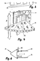
- FIG. 4 shows the assembly unit, drawn in FIG. 2 and assembled from a support profile 1 and a front profile 17, with a fragment of a shelf 21.
- This shelf 21 rests on a - dashed - shelf shelf support 22 which is non-positively and positively fixed via a clamping mechanism in the T-shaped channel 5 of the profile rail 2 and can be continuously adjusted along this channel (see arrow Z).
- FIG. 5 shows the assembly unit drawn in FIG. 2, assembled from a support profile 1 and a front profile 17, each with a partition 23 or end wall 24 inserted parallel to the plane of symmetry S of the profile rail 2 into the corresponding guide grooves 4 or 10 and one perpendicular to the plane of symmetry S. rear wall 25 inserted into the second guide groove 6.
- FIG. 6 shows the construction example drawn in FIG. 5 in cross section. It can be seen in particular that a closed wall system can be created via the guide grooves 4, 6 and 10 integrated in the support profile 1.
- FIG. 7 shows a cross-sectional illustration of an assembly unit composed of a support profile 1 and a front profile 17, into which a lamp 26 is integrated.
- this lamp 26 is mounted along the assembly webs 14 and ensures optimum illumination or illumination of the products to be represented.
- This type of mounting of the lighting fixtures shows a particular advantage over the prior art.
Landscapes
- Assembled Shelves (AREA)
- Mirrors, Picture Frames, Photograph Stands, And Related Fastening Devices (AREA)
- Freezers Or Refrigerated Showcases (AREA)
- Absorbent Articles And Supports Therefor (AREA)
- Professional, Industrial, Or Sporting Protective Garments (AREA)
- Respiratory Apparatuses And Protective Means (AREA)
- Arrangement Of Elements, Cooling, Sealing, Or The Like Of Lighting Devices (AREA)
Abstract
Description
- Die vorliegende Erfindung bezieht sich auf ein Stützprofil zum Aufbau eines Ladenbausystems oder dergleichen.
- Ladenbausysteme, Regalsysteme, Displaysysteme ... sie begegnen uns vielfach und in vielfältiger Form. Die Qualität und Praktikabilität eines derartigen Ladenbausystems zum Beispiel ist im Hinblick auf die Aufgabenstellung, und zwar sowohl bezüglich der bestimmungsgemäßen Verwendung als Präsentationsmittel, als auch bezüglich des Erscheinungsbildes, also der ästhetisch bedingten Werbewirksamkeit, ganz wesentlich dadurch bestimmt, welche Gestaltungsfreiheit der Benutzer hat. Ein hochwertiges Ladenbausystem ist letztlich also daran zu erkennen, wieviel Gestaltungsfreiheit dem Nutzer offensteht und welcher Art diese Gestaltungsfreiheit ist.
- Die der vorliegenden Erfindung zugrunde liegende Aufgabe besteht darin, ein Stützprofil zum Aufbau von Ladenbausystemen oder dergleichen modular aufbaubaren Präsentationssystemen anzugeben, das ein Optimum an Variabilität zuläßt. Neben einer konstruktions- und werkstoffbedingten, selbstverständlich hohen Stabilität als Trag- und Stützelement, soll sich das mit dem erfindungsgemäßen Stützprofil aufzubauende Präsentationssystem insbesondere auch leicht und problemlos aufbauen und auch wieder demontieren lassen.
- Die vorgenannte Aufgabe wird dadurch gelöst, daß eine im wesentlichen U-förmige Profilschiene vorgesehen ist, die a) spiegelsymmetrisch zur Symmetrieebene des U an den Außenseiten der parallel zueinander liegenden Seitenwände eine Mehrzahl von parallel oder senkrecht zur Symmetrieebene orientierten Führungsnuten zur Aufnahme von prallel oder senkrecht zur Symmetrieeben orientierten Wandelementen vorgesehen ist, und daß b) an der Grundseite des U seitlich nach außen gerichtete Profilnasen zum Einrasten eines mit komplementären Rastnuten versehenen Frontprofils ausgebildet sind.
- Damit steht ein Grundprofil zur Verfügung, das gleichermaßen als Aufbau- und Frontelement für Ladenbausysteme verwendbar ist, und insoweit mit einem Frontprofil beliebiger Form und Farbgebung verblendet werden kann und das auch als Knotenpunkt für ein veränder- und erweiterbares Wandsystem dient.
- Konstruktive Detaillösungen bezüglich dieser Stützprofile sind Gegenstand der Unteransprüche. Dabei sind auch weitere vorteilhafte Merkmale im Hinblick auf ein komplettes Ladenbausystem angegeben.
- Die Erfindung wird im folgenden anhand der Zeichnung näher erläutert. Diese zeigt in
- Fig. 1
- den Querschnitt der Grundelemente für ein Ladenbausystem, und zwar den Querschnitt eines Stützprofils, sowie eines Frontprofils und einer Deckschiene;
- Fig. 2
- eine Perspektivdarstellung eines aus Stützprofil und Frontprofil bestehenden Frontelements;
- Fig. 3
- eine Mehrzahl beispielhafter Frontflächengestaltungen von Frontprofilen;
- Fig. 4
- eine Perspektivdarstellung des Frontelements nach Fig. 2 mit einem Regalbodenträger;
- Fig. 5
- eine Perspektivdarstellung des Frontelements nach Fig. 2 mit angefügten Wandelementen;
- Fig. 6
- den Querschnitt des gemäß der Darstellung nach Fig. 5 montierten Elementes;
- Fig. 7
- den Querschnitt eines Stützprofils mit Frontprofil und einer im Stützprofil integrierten Beleuchtung.
- Fig. 1 zeigt die Grundelemente eines Ladenbausystems, und zwar zunächst das Kernstück der vorliegenden Erfindung, das Stützprofil 1 im Querschnitt. Die geometrische Grundform dieses Stützprofils 1 ist durch eine U-förmige Profilschiene 2 bestimmt, deren Seitenwände 3 konstruktiv in ganz spezifischer Weise ausgebildet sind, und zwar wie folgt:
Die freien Stirnseiten der Seitenwände 3 sind als rechteckige (erste) Führungsnuten 4 konfiguriert, deren Symmetrielinien parallel zur Symmetrieebene S der Profilschiene 2 verlaufen. Die ersten Führungsnuten 4 bilden so einen offenen Kanal, in den - vergleiche Fig. 5 - ein parallel zur Seitenwand 3 orientiertes Wandelement eingefügt werden kann. An diese ersten Führungsnuten 4 schließt ein T-förmiger Kanal 5 an, dessen parallel zu den Seitenwänden 3 liegende äußere Begrenzungen mit den Außenseiten der ersten Führungsnuten 4 fluchten. Dieser T-förmige Kanal 5 dient - vergleiche Fig. 4 - zur Aufnahme längs des T-förmigen Kanals 5 stufenlos verstellbarer Regalbodenträger für Regelböden oder dergleichen Ablageböden. An den T-förmigen Kanal 5 schließt je eine (zweite) Führungsnut 6 an, deren Symmetrielinie senkrecht zur Symmetrieebene S der U-förmigen Profilschiene 2 verläuft. In diese zweiten Führungsnuten 6 können - vergleiche Fig. 5 - senkrecht zur Symmetrieebene S gerichtete Wandelemente eingefügt werden. - Die Grundseite der U-förmigen Profilschiene 2 weist seitlich je einen überstand 8 auf, an den im Abstand zu den Seitenwänden 3 in Richtung von der Grundseite 7 weg orientierte Profilnasen 9 angearbeitet sind. Gemäß der zeichnerischen Darstellung nach Fig. 1 sind diese Profilnasen 9 wie folgt ausgebildet: Der überstand 8 beginnt im Abstand von der Grundseite 7 und bildet eine Seite der genannten zweiten Führungsnuten 6. In der durch den T-förmigen Kanal 5 und die erste Führungsnut 4 definierten, parallel zur Seitenwand 3 liegenden Ebene schließt an den überstand 8 eine (dritte) Führungsnut 10 an, deren Grundseite in der Ebene der Grundseite 7 der Profilschiene 2 liegt, und an deren freier Wandung die Profilnase 9 als vorstehender Längssteg 11 ausgebildet ist. Die freie Stirnseite der genannten Wandung weist einen zur Profilschiene 2 hingerichteten Ansatz 12 auf. Die von der Profilschiene 2 entfernte, in der Ebene der Grundseite 7 liegende Ecke der dritten Führungsnut 10 ist abgeschrägt, und zwar so, daß diese Schräge 13 selbst insofern Teil der Profilnasen 9 ist, als die Schräge 13 in eine Hinterschneidung übergeht, wodurch sich letztlich der Längssteg 11 ausbildet.
- Das insoweit beschrieben Stützprofil 1 erfüllt die zugrunde liegenden Grundaufgaben, nämlich - über die Profilnasen 9 - ein Frontprofil 17 aufzunehmen, - über die Führungsnuten 4, 6, 10 - Wandelemente zu arretieren und - über die T-förmigen Kanäle 5 - Regalböden oder dergleichen zu halten. Wie in Fig. 1 dargestellt weist die Profilschiene 2 im Inneren zwei aufeinander zu gerichtete Montagestege 14 auf, über die - vergleiche Fig. 7 - eine Lampe oder dergleichen integriert werden kann. An den freien Stirnseiten der U-förmigen Profilschiene 2 sind darüberhinaus zur Symmetrieebene S hin gerichtete Stege 15 vorgesehen, die als (Aufnahme-) Rast für eine aufsetzbare Deckschiene 16 dienen.
- Diese Deckschiene 16 besteht aus einem Flachmaterial, das seitlich mit den Stegen 15 korrespondierende Hinterschneidungen aufweist, über die die Deckschiene 16 an der Profilschiene 2 eingeclipst werden kann (vergleiche Pfeil X).
- Die genannten Profilnasen 9 dienen der Aufklemmung eines Frontprofils 17, das hier in Fig. 1 als dreieckiges Formteil ausgebildet ist. Dieses dreieckige Formteil weist an den beiden freien Dreiecksseiten je ein Paar konjugierter Vorsprünge 18, 19 auf, die gemeinsam eine Rastnut 20 definieren. Diese Rastnut 20 ist insofern exakt komplementär zu der an der U-förmigen Profilschiene 2 angearbeiteten Profilnase 9 ausgebildet, daß das Frontprofil 17 federnd auf die Grundseite 7 der Profilschiene 2 aufgesteckt werden kann (vergleiche Pfeil Y).
- Das Frontprofil 17 wird somit über ein einfaches Aufstecken form- und kraftschlüssig am Stützprofil 1 aufgeclipst und bildet einen formschönen Abschluß dieses Stützprofils 1.
- Fig. 2 zeigt eine aus einem Stützprofil 1 und einem Frontprofil 17 zusammengefügte Montageeinheit. Der einfache Montage- beziehungsweise Aufsteckvorgang der Frontprofile 17 an ein aus Stützprofilen 1 montiertes Ladenbausystem ermöglicht letztlich eine außergewöhnliche Variabilität. Die Frontprofile 17 können dabei nicht nur bezüglich der Material- und Farbwahl an sich, sowie der Oberflächenbearbeitung beliebig gestaltet sein, sondern auch bezüglich der Form der Verblendung.
- Fig. 3 zeigt weitere Beispiele für Querschnittsformen der Frontprofile 17, und zwar kann dieses Frontprofil 17 in Form eines U oder eines Halbkreises, aber auch mit einer Wellenform ausgebildet sein; selbstverständlich ist es auch möglich, die Außenseite mit einer Spiegelauflage oder einer Werbefläche zu bestücken. Wesentlich ist insofern nur, daß die unterschiedlichen Profilformen an den freien Stirnseiten jeweils die zu den Profilnasen 9 komplementären Rastnuten 20 aufweisen, da nur so der mit der erfindungsgemäßen Konzeption angestrebte Vorteil der einfachen Montage- und Demontierarbeit gewährleistet, beziehungsweise überhaupt erreichbar ist.
- Fig. 4 zeigt die in Fig. 2 gezeichnete aus einem Stützprofil 1 und einem Frontprofil 17 zusammengefügte Montageeinheit mit einem Bruchstück eines Regalbodens 21. Dieser Regalboden 21 liegt auf einem - gestrichelt gezeichneten - Regalbodenträger 22 auf, der kraft- und formschlüssig über eine Klemm-Mechanik im T-förmigen Kanal 5 der Profilschiene 2 fixiert und längs dieses Kanals kontinuierlich verstellt werden kann (vergleiche Pfeil Z).
- Fig. 5 zeigt die in Fig. 2 gezeichnete, aus einem Stützprofil 1 und einem Frontprofil 17 zusammengefügte Montageeinheit mit je einer parallel zur Symmetrieebene S der Profilschiene 2 in den korrespondieren Führungsnuten 4 beziehungsweise 10 eingesteckten Trennwand 23 beziehungsweise Abschlußwand 24 und einer senkrecht zur Symmetrieebene S in der zweiten Führungsnut 6 eingefügten Rückwand 25. Über die spezifische Ausgestaltung des Stützprofils 1 ist es letztlich möglich, Wandelemente beliebiger Art auch in vielfältiger Anordnungen relativ zueinander auszurichten.
- Fig. 6 zeigt das in Fig. 5 gezeichnete Aufbaubeispiel im Querschnitt. Dabei ist insbesondere zu erkennen, daß über die im Stützprofil 1 integrierten Führungsnuten 4, 6 und 10 ein geschlossenes Wandsystem erstellt werden kann.
- Fig. 7 zeigt eine Querschnittsdarstellung einer aus einem Stützprofil 1 und einem Frontprofil 17 zusammengefügten Montageeinheit, in die eine Lampe 26 integriert ist. Diese Lampe 26 wird - wie erwähnt - längs der Montagestege 14 montiert und gewährleistet eine optimale Aus- beziehungsweise Beleuchtung der zu repräsentierenden Produkte. Gerade diese Art der Montage der Beleuchtungskörper läßt dem Stand der Technik gegenüber einen besonderen Vorzug erkennen.
Claims (7)
- Stützprofil zum Aufbau eines Ladenbausystems oder dergleichen,
gekennzeichnet durch eine U-förmige Profilschiene (2) mit folgenden Konstruktionsmerkmalen:a) spiegelsymmetrisch zur Symmetrieebene (S) des U ist an den Außenseiten der parallel zueinander liegenden Seitenwände (3) eine Mehrzahl parallel oder senkrecht zur Symmetrieebene (S) orientierter Führungsnuten (4, 6, 10) zur Aufnahme von parallel oder senkrecht zur Symmetrieebene orientierten Wandelementen (23, 24, 25) vorgesehen,b) an der Grundseite (7) des U sind seitlich nach außen gerichtete Profilnasen (9) zum Einrasten eines mit komplementären Rastnuten (20) versehenen Frontprofils (17) ausgebildet. - Stützprofil nach Anspruch 1,
dadurch gekennzeichnet,
daß die Profilnasen (9) je an einer den Seitenwänden (3) des U gegenüber vorstehenden Führungsnut (10) zur Aufnahme eines parallel zur Symmetrieebene (S) orientierten Wandelements (24) angearbeitet sind. - Stützprofil nach Anspruch 1 oder 2,
dadurch gekennzeichnet,
daß der Grundseite des U je eine Führungsnut (6, 10) zur Aufnahme eines parallel und eines senkrecht zur Symmetrieebene (S) orientierten Wandelements (24 beziehungsweise 25) benachbart ist. - Stützprofil nach einem der Ansprüche 1 bis 3,
dadurch gekennzeichnet,
daß je eine Führungsnut (4) zur Aufnahme eines parallel zur Symmetrieebene (S) orientierten Wandelements (23) den freien Stirnseiten der Schenkel des U benachbart vorgesehen ist. - Stützprofil nach Anspruch 4,
dadurch gekennzeichnet,
daß die der Grundseite (7) des U benachbarte Führungsnut (6) zur Aufnahme eines senkrecht zur Symmetrieebene (S) orientierten Wandelements (25) und die Führungsnut (4) an der freien Stirnseite der Schenkel des U einen T-förmigen Kanal (5) zur form- und kraftschlüssigen Aufnahme von Regalbodenträgern (22) für Einlegeböden (21) oder dergleichen begrenzen. - Stützprofil nach einem der Ansprüche 1 bis 5,
dadurch gekennzeichnet,
daß die U-förmige Profilschiene an der offenen Seite des U Rastmittel zur Aufnahme einer komplementär ausgebildeten Deckschiene (16) aufweist. - Stützprofil nach einem der Ansprüche 1 bis 6,
dadurch gekennzeichnet,
daß im Innenraum der U-förmigen Profilschiene (2) Montagestege (14) zur Fixierung eines Beleuchtungskörpers (Lampe 26) vorgesehen sind.
Applications Claiming Priority (2)
| Application Number | Priority Date | Filing Date | Title |
|---|---|---|---|
| DE4015242A DE4015242A1 (de) | 1990-05-10 | 1990-05-10 | Stuetzprofil fuer ein ladenbausystem oder dergleichen |
| DE4015242 | 1990-05-10 |
Publications (2)
| Publication Number | Publication Date |
|---|---|
| EP0456104A1 true EP0456104A1 (de) | 1991-11-13 |
| EP0456104B1 EP0456104B1 (de) | 1995-01-25 |
Family
ID=6406239
Family Applications (1)
| Application Number | Title | Priority Date | Filing Date |
|---|---|---|---|
| EP91107063A Expired - Lifetime EP0456104B1 (de) | 1990-05-10 | 1991-05-02 | Stützprofil für ein Ladenbausystem oder dergleichen |
Country Status (3)
| Country | Link |
|---|---|
| EP (1) | EP0456104B1 (de) |
| AT (1) | ATE117518T1 (de) |
| DE (2) | DE4015242A1 (de) |
Cited By (6)
| Publication number | Priority date | Publication date | Assignee | Title |
|---|---|---|---|---|
| AT409707B (de) * | 1995-02-09 | 2002-10-25 | Hohenloher Spezialmoebel | Demonstrationsschrank |
| ES2233120A1 (es) * | 2001-08-01 | 2005-06-01 | Rafael Sotillo Crespo | Sistema de perfiles con estructura abierta adecuados para mobiliario. |
| DE102004026975B4 (de) * | 2004-03-03 | 2008-03-13 | Schulze, Andreas, Dipl.-Designer | Bausatz zur Erstellung von Regalen, Raumteilern, Büromöbeln o.dgl. |
| WO2012114299A1 (en) * | 2011-02-23 | 2012-08-30 | Liexco S.A. | Modular closet system |
| DE102011050615A1 (de) * | 2011-05-24 | 2012-11-29 | Alfer Aluminium Gesellschaft Mbh | Profilelement für Möbel, insbesondere Regale |
| GB2543335A (en) * | 2015-10-15 | 2017-04-19 | Spacestor Ltd | Side Wall Track |
Families Citing this family (4)
| Publication number | Priority date | Publication date | Assignee | Title |
|---|---|---|---|---|
| DE9420592U1 (de) * | 1994-12-23 | 1995-07-27 | Erbslöh AG, 42553 Velbert | Beschlag zur Abstützung von Fachböden o.dgl. |
| DE29600186U1 (de) * | 1996-01-10 | 1996-02-22 | SieMatic Möbelwerke GmbH & Co, 32584 Löhne | Kastenmöbel, insbesondere Küchenmöbelschrank mit integrierter Rückwandleuchte |
| DE29902682U1 (de) | 1999-02-16 | 1999-05-06 | Henseler, Rudolf, 33613 Bielefeld | Beleuchtungseinrichtung für Möbel, Regale u.dgl. |
| EP3967183B1 (de) * | 2020-09-15 | 2026-04-22 | Nolte Küchen GmbH & Co. KG | Korpusmöbelanordnung mit beleuchtetem profil |
Citations (5)
| Publication number | Priority date | Publication date | Assignee | Title |
|---|---|---|---|---|
| AT263264B (de) * | 1964-12-31 | 1968-07-10 | Lust Kg Ernst | Schrank bzw. Schrankwand |
| DE1940327A1 (de) * | 1969-08-08 | 1971-02-18 | Karl Broecker | Profilierte Stange zur Verwendung in der Bau- und Moebelindustrie |
| US4022517A (en) * | 1975-12-08 | 1977-05-10 | Amity Leather Products Company | Display case for small articles |
| US4123129A (en) * | 1976-11-18 | 1978-10-31 | Tektronix, Inc. | Modular electronic instrument cabinets |
| EP0226496A1 (de) * | 1985-11-18 | 1987-06-24 | Jean Stoltz | Profile und Zusatzstücke zum Zusammensetzen von Möbeln |
-
1990
- 1990-05-10 DE DE4015242A patent/DE4015242A1/de not_active Withdrawn
-
1991
- 1991-05-02 DE DE59104361T patent/DE59104361D1/de not_active Expired - Fee Related
- 1991-05-02 EP EP91107063A patent/EP0456104B1/de not_active Expired - Lifetime
- 1991-05-02 AT AT91107063T patent/ATE117518T1/de not_active IP Right Cessation
Patent Citations (5)
| Publication number | Priority date | Publication date | Assignee | Title |
|---|---|---|---|---|
| AT263264B (de) * | 1964-12-31 | 1968-07-10 | Lust Kg Ernst | Schrank bzw. Schrankwand |
| DE1940327A1 (de) * | 1969-08-08 | 1971-02-18 | Karl Broecker | Profilierte Stange zur Verwendung in der Bau- und Moebelindustrie |
| US4022517A (en) * | 1975-12-08 | 1977-05-10 | Amity Leather Products Company | Display case for small articles |
| US4123129A (en) * | 1976-11-18 | 1978-10-31 | Tektronix, Inc. | Modular electronic instrument cabinets |
| EP0226496A1 (de) * | 1985-11-18 | 1987-06-24 | Jean Stoltz | Profile und Zusatzstücke zum Zusammensetzen von Möbeln |
Cited By (10)
| Publication number | Priority date | Publication date | Assignee | Title |
|---|---|---|---|---|
| AT409707B (de) * | 1995-02-09 | 2002-10-25 | Hohenloher Spezialmoebel | Demonstrationsschrank |
| ES2233120A1 (es) * | 2001-08-01 | 2005-06-01 | Rafael Sotillo Crespo | Sistema de perfiles con estructura abierta adecuados para mobiliario. |
| ES2233120B1 (es) * | 2001-08-01 | 2006-10-01 | Rafael Sotillo Crespo | Sistema de perfiles con estructura abierta adecuados para mobiliario. |
| DE102004026975B4 (de) * | 2004-03-03 | 2008-03-13 | Schulze, Andreas, Dipl.-Designer | Bausatz zur Erstellung von Regalen, Raumteilern, Büromöbeln o.dgl. |
| WO2012114299A1 (en) * | 2011-02-23 | 2012-08-30 | Liexco S.A. | Modular closet system |
| BE1019727A3 (nl) * | 2011-02-23 | 2012-10-02 | Liexco Sa | Modulair kastsysteem. |
| DE102011050615A1 (de) * | 2011-05-24 | 2012-11-29 | Alfer Aluminium Gesellschaft Mbh | Profilelement für Möbel, insbesondere Regale |
| DE102011050615B4 (de) | 2011-05-24 | 2022-02-10 | Alfer Aluminium Gesellschaft Mbh | Profilelement für Möbel, insbesondere Regale |
| GB2543335A (en) * | 2015-10-15 | 2017-04-19 | Spacestor Ltd | Side Wall Track |
| GB2543335B (en) * | 2015-10-15 | 2018-09-19 | Spacestor Ltd | Side Wall Track |
Also Published As
| Publication number | Publication date |
|---|---|
| ATE117518T1 (de) | 1995-02-15 |
| DE59104361D1 (de) | 1995-03-09 |
| EP0456104B1 (de) | 1995-01-25 |
| DE4015242A1 (de) | 1991-11-14 |
Similar Documents
| Publication | Publication Date | Title |
|---|---|---|
| EP0901332B1 (de) | Modulares inneneinrichtungssystem | |
| EP0789944B1 (de) | Rahmengestell aus rahmenschenkeln und tiefenstreben | |
| DE2933303A1 (de) | Befestigungsvorrichtung fuer wandschraenkchen, spiegel, regale u.dgl. | |
| EP0456104B1 (de) | Stützprofil für ein Ladenbausystem oder dergleichen | |
| DE19837367C2 (de) | Rahmenprofil für einen Schaltschrank | |
| EP2767644A1 (de) | Stellwand für einen Raumteiler | |
| DE3688113T2 (de) | Elementensatz fuer die einrichtung von ausstellungsraeumen, geschaeften und anderen orten. | |
| DE2845017A1 (de) | Anordnung zur erstellung von wand- und/oder deckenkonstruktionen, insbesondere im messebau | |
| DE19909440C1 (de) | Anordnung zur Befestigung von Regalböden | |
| DE19818930A1 (de) | Präsentationshalterung mit Rahmen und Rückwand | |
| DE4415037A1 (de) | Regalanordnung und/oder Schaugestell | |
| DE102019200715A1 (de) | Profil zum Aufbau von Betriebseinrichtungen und Betriebseinrichtung | |
| DE9312847U1 (de) | Bausatz für ein modulares Rahmenwerk für Schränke, Regale, Gestelle u.dgl. | |
| DE4406212A1 (de) | Tragsystem | |
| DE19836435C1 (de) | Türanlage, insbesondere Türsprechanlage | |
| DE10160740A1 (de) | Bausatz zur Errichtung eines Präsentationsstands für eine Messe oder dgl. | |
| DE102005056437B3 (de) | Raumteiler | |
| WO2000047085A1 (de) | Modular erweiterbares traggestell mit flächenelementen aus drahtgittern zur aufnahme von artikeln | |
| DE9312536U1 (de) | Spiegelsymmetrisches Stützprofil für ein Ladenbausystem o.dgl. | |
| DE29502324U1 (de) | Stütz- und Verblendungsprofil für Regalsysteme o.dgl. | |
| DE29821761U1 (de) | Verkleidungssystem für eine Wanne, vorzugsweise Badewanne | |
| DE19958356A1 (de) | Verkleidungssystem für eine Wanne, vorzugsweise Badewanne | |
| DE29820569U1 (de) | Regal | |
| DE20023198U1 (de) | Modular erweiterbares Traggestell mit Flächenelementen aus Drahtgittern zur Aufnahme von Artikeln | |
| DE4430320A1 (de) | Möbelsystem für die Erstellung von Regalen, Schränken, Vitrinen, Tischen und dergleichen |
Legal Events
| Date | Code | Title | Description |
|---|---|---|---|
| PUAI | Public reference made under article 153(3) epc to a published international application that has entered the european phase |
Free format text: ORIGINAL CODE: 0009012 |
|
| AK | Designated contracting states |
Kind code of ref document: A1 Designated state(s): AT BE CH DE DK ES FR GB IT LI LU NL SE |
|
| 17P | Request for examination filed |
Effective date: 19911213 |
|
| 17Q | First examination report despatched |
Effective date: 19930603 |
|
| GRAA | (expected) grant |
Free format text: ORIGINAL CODE: 0009210 |
|
| AK | Designated contracting states |
Kind code of ref document: B1 Designated state(s): AT BE CH DE DK ES FR GB IT LI LU NL SE |
|
| PG25 | Lapsed in a contracting state [announced via postgrant information from national office to epo] |
Ref country code: IT Free format text: LAPSE BECAUSE OF FAILURE TO SUBMIT A TRANSLATION OF THE DESCRIPTION OR TO PAY THE FEE WITHIN THE PRESCRIBED TIME-LIMIT;WARNING: LAPSES OF ITALIAN PATENTS WITH EFFECTIVE DATE BEFORE 2007 MAY HAVE OCCURRED AT ANY TIME BEFORE 2007. THE CORRECT EFFECTIVE DATE MAY BE DIFFERENT FROM THE ONE RECORDED. Effective date: 19950125 Ref country code: GB Effective date: 19950125 Ref country code: FR Effective date: 19950125 Ref country code: NL Effective date: 19950125 Ref country code: DK Effective date: 19950125 Ref country code: BE Effective date: 19950125 Ref country code: ES Free format text: THE PATENT HAS BEEN ANNULLED BY A DECISION OF A NATIONAL AUTHORITY Effective date: 19950125 |
|
| REF | Corresponds to: |
Ref document number: 117518 Country of ref document: AT Date of ref document: 19950215 Kind code of ref document: T |
|
| REF | Corresponds to: |
Ref document number: 59104361 Country of ref document: DE Date of ref document: 19950309 |
|
| PG25 | Lapsed in a contracting state [announced via postgrant information from national office to epo] |
Ref country code: SE Effective date: 19950425 |
|
| PG25 | Lapsed in a contracting state [announced via postgrant information from national office to epo] |
Ref country code: AT Effective date: 19950502 |
|
| PG25 | Lapsed in a contracting state [announced via postgrant information from national office to epo] |
Ref country code: CH Effective date: 19950531 Ref country code: LU Free format text: LAPSE BECAUSE OF NON-PAYMENT OF DUE FEES Effective date: 19950531 Ref country code: LI Effective date: 19950531 |
|
| EN | Fr: translation not filed | ||
| NLV1 | Nl: lapsed or annulled due to failure to fulfill the requirements of art. 29p and 29m of the patents act | ||
| GBV | Gb: ep patent (uk) treated as always having been void in accordance with gb section 77(7)/1977 [no translation filed] |
Effective date: 19950125 |
|
| PLBE | No opposition filed within time limit |
Free format text: ORIGINAL CODE: 0009261 |
|
| STAA | Information on the status of an ep patent application or granted ep patent |
Free format text: STATUS: NO OPPOSITION FILED WITHIN TIME LIMIT |
|
| 26N | No opposition filed | ||
| REG | Reference to a national code |
Ref country code: CH Ref legal event code: PL |
|
| PGFP | Annual fee paid to national office [announced via postgrant information from national office to epo] |
Ref country code: DE Payment date: 19990805 Year of fee payment: 9 |
|
| PG25 | Lapsed in a contracting state [announced via postgrant information from national office to epo] |
Ref country code: DE Free format text: LAPSE BECAUSE OF NON-PAYMENT OF DUE FEES Effective date: 20010301 |