EP0456110A2 - Dispositif et procédé de balayage optique d'un document - Google Patents
Dispositif et procédé de balayage optique d'un document Download PDFInfo
- Publication number
- EP0456110A2 EP0456110A2 EP91107078A EP91107078A EP0456110A2 EP 0456110 A2 EP0456110 A2 EP 0456110A2 EP 91107078 A EP91107078 A EP 91107078A EP 91107078 A EP91107078 A EP 91107078A EP 0456110 A2 EP0456110 A2 EP 0456110A2
- Authority
- EP
- European Patent Office
- Prior art keywords
- image plane
- attachment
- spot
- optical
- deflection device
- Prior art date
- Legal status (The legal status is an assumption and is not a legal conclusion. Google has not performed a legal analysis and makes no representation as to the accuracy of the status listed.)
- Withdrawn
Links
Images



Classifications
-
- G—PHYSICS
- G02—OPTICS
- G02B—OPTICAL ELEMENTS, SYSTEMS OR APPARATUS
- G02B26/00—Optical devices or arrangements for the control of light using movable or deformable optical elements
- G02B26/08—Optical devices or arrangements for the control of light using movable or deformable optical elements for controlling the direction of light
- G02B26/10—Scanning systems
-
- G—PHYSICS
- G02—OPTICS
- G02B—OPTICAL ELEMENTS, SYSTEMS OR APPARATUS
- G02B13/00—Optical objectives specially designed for the purposes specified below
- G02B13/08—Anamorphotic objectives
-
- G—PHYSICS
- G02—OPTICS
- G02B—OPTICAL ELEMENTS, SYSTEMS OR APPARATUS
- G02B3/00—Simple or compound lenses
- G02B3/02—Simple or compound lenses with non-spherical faces
- G02B3/04—Simple or compound lenses with non-spherical faces with continuous faces that are rotationally symmetrical but deviate from a true sphere, e.g. so called "aspheric" lenses
Definitions
- the invention relates to a method for point-wise optical scanning of a template on an inner cylindrical image plane with a beam deflected by a deflection device and devices for carrying out the method.
- the deflection device consists of a holographic grating.
- a grid is very difficult to manufacture exactly and accordingly expensive.
- this deflection device can only produce a round spot on a curved image plane around the deflection device rotating in the optical radiation incidence axis.
- DE-PS 33 27 215 discloses a device for deflecting an axially incident light beam onto an image plane located around a rotating deflection device.
- An axially displaceable annular refractive element around a deflecting mirror around serves to deflect the light beam from the axial direction onto the image plane, this light-refractive element being spatially separated from the deflecting mirror and not rotating with it. This document does not disclose which spot shape is useful for scanning.
- a deflection device is known in which a prism is placed on an obliquely aligned plane rotating mirror to reduce the unbalance.
- deflection optics In both documents there are no additional features for the design of the deflection device, which is referred to as deflection optics, and no statements are made regarding an advantageous spot shape.
- a deflection device is required to deflect an incoming beam in the direction of the image plane.
- the rotation of this deflection device achieves an optical sweep along a line on the image plane.
- the movement in a drum scanner takes place either by moving the original or by moving the deflection device along the optical axis. Only when the optics for generating the spot shape is located on the rotating deflection device or is arranged rotationally symmetrically around the deflection device, does the spot shape always remain constant and a simple construction is obtained.
- a well-squared field profile is achieved when the amount of the difference between the major and minor axes of the elliptical spot corresponds to the speed of the spot on the image plane multiplied by the active time.
- the drum scanner shown schematically in Fig. 1 has a laser (2) as a light source.
- the beam (6) generated by him is focused by a first optical system (3), shown here schematically by a single lens.
- a first optical system (3) shown here schematically by a single lens.
- AOM (4) acoustic wave optical modulator
- the beam of rays (7b) emerging from the AOM (4) is converted into a beam of rays (9) parallel to the axis by further optics (5), represented here schematically by a single lens.
- the two optics (3, 5) and the AOM (4) are summarized under the term beam generating optics (1).
- the beam generating optics (1) behind the laser (2) provide a beam (9) with a parallel beam path around the optical axis (16).
- a carrier part (11) which is essentially a solid, obliquely cut circular cylinder.
- the obliquely cut circular cylinder surface serves as a mirror surface (12).
- the carrier part (11) with a mirror surface (12) is called a deflecting element (18) or also a rotating mirror.
- the rotationally symmetrical beam (9) strikes the mirrored surface (12) of this carrier part (11) and is deflected by the mirror surface (12) towards the inner cylindrical image plane (17).
- the beam (10) changed in cross section by the non-rotationally symmetrical, aspherical mirror surface (12) moves on the image plane (17) curved around the axis of rotation in the arrow direction (14) along a scan line (19).
- the mirror surface must generally be aspherical.
- the spot has (20) a fixed orientation relative to the scan line (19). If the beam (9) is axially parallel, the deflecting element (18) can also be moved without problems along the axis of rotation (13) or optical axis (16) without the size of the spot (20) changing. An oriented spot is generated in this way without the need for additional optical elements, which spot has an elliptical shape when the aspherical parameters are selected appropriately.
- the parameters are advantageously chosen so that the incident beam (9) is focused in one section on the image plane (17).
- FIG. 2 shows the elliptical spot (20) from FIG. 1, which is generated on the image plane (17) by the scanner shown schematically in FIG. 1.
- the size of the spot can be determined by varying the radii of the aspherical mirror surface (12).
- the spot (20) is advantageously oriented transversely to the scanning direction (14) on the image plane (17).
- the spot (20) moves on the image plane (17) in the scanning direction (14) along the scanning line (19). Since the data is recorded from a template or the exposure of a film takes place during the rotation, the active time (eg exposure time) of the spot (20) is limited in time. During the active time, the spot (20) moves on the image plane (17) and thus on the scan line (19).
- this magnitude must be the product of the spot speed on the image plane (17) and scan active time (eg exposure time) match.
- the approximation to the square field in the image plane (17) succeeds the more precisely the greater the amount of the ratio of the large to the small axis of the spot ellipse.
- This requires a longer active time, which limits the amount of the ratio of the two ellipse axes in practice.
- the field (21) swept through the spot (20) during the active time is determined by the intensity distribution of the beam (gray profile).
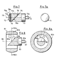
- an aspherical mirror surface (38) is realized on the back of an attachment (34) which is transparent for the wavelength used.
- the attachment (34) is attached to the front surface (39) of a carrier part (33) with an adhesive layer (35), the carrier part (33) being an obliquely cut circular cylinder.
- the front surface (39) of this circular cylinder is adapted to the shape of the mirrored rear surface (38) of the transparent attachment (34) so that the fluctuations in the thickness of the adhesive layer do not become too great.
- the attachment of the aspherical mirror surface (38) on the rear surface of the attachment (34) has the advantage that an otherwise necessary kit layer of different thicknesses instead of the adhesive layer (35) when attaching the mirror surface on the front surface (39) of the carrier part (33) no negative Has influence on the optical imaging properties of the deflection device and a double, precise aspherical processing can be omitted.
- the beam entry surface (32) and the beam exit surface (31) of the transparent attachment (34) are flat and exert no optical effect on the beam bundle coming from the beam generation optics (1 in FIG. 1).
- the optical effect occurs only through the aspherical, mirrored rear surface (38) of the attachment (34), which ensures both a deflection from the optical axis (36) by a predetermined angle (preferably 90 °) and also the change in the beam geometry of the incident, axially parallel beam into a beam with elliptical beam geometry.
- the optically unused parts (30) of the attachment (34) and the parts (30a) of the carrier part that are present in this area (33) removed.
- the carrier part (33) has a tapered drive shaft (33a).
- the axis of rotation (37) of the deflection device is exactly in the extension of the optical axis (36) the beam generating optics.
- the adhesive layer (35) in FIG. 3 and in the following FIGS. 4-7 is drawn oversized.
- the deflection device shown in FIGS. 4 and 4a does not require an aspherical surface which is difficult to produce on the front surface of the carrier part or on the back of the attachment. This leads to a substantial reduction in the manufacturing effort and, if an attachment is used, to a substantial reduction in the adjustment effort.
- the perpendicular bisectors of the circular cylindrical sections of the attachment (44) and the support part (43) are in a line, which correspond to both the optical axis (46) and the axis of rotation (47) while the deflection device is being used in the scanner.
- the attachment (44) and the carrier part (43) are joined together, they have a common, smooth outer surface. This leads to a very large reduction in the imbalance, however, only if the specific weight of the attachment (44) and the support part (43) matches as closely as possible.
- the axially parallel beam of rays penetrates the attachment (44) undisturbed by the beam generation optics through the flat, circular beam entry surface (42) and is passed through the mirrored rear surface (48) The inclination of the rear surface (48) is redirected in the direction of the image plane.
- the round outer surface (41) acts like a cylindrical lens and focuses the beam of rays in the direction of the image plane.
- the front surface (49) of the carrier part (43) can also be mirrored, since both surfaces (48, 49) are flat. Then the attachment (44) and the carrier part (43) must be connected to one another by a kit layer instead of an adhesive layer (45). This also applies to the further deflection devices in FIGS. 5-7.
- the attachment (54) shown in FIGS. 5 and 5a differs from the attachment (44) shown in FIG. 4 in that its radiation entry surface (52) has an optical effect. It is thereby achieved that the beam geometry behind the deflection device consisting of attachment (54) and carrier part (53) does not have to be made dependent on the focusing effect of the beam generation optics on the beam. In addition, the size of the spot in both main axes can also be determined by the beam entry surface (52) (taking into account the other parameters) in the case of a beam bundle parallel to the axis.
- the attachment (54) and the support part (53) consist of two obliquely cut circular cylinders of the same diameter connected by an adhesive layer (55), the cylinder axes of which are connected to the optical axis (56) and the axis of rotation (57) of the deflection device coincide.
- the rear surface (58) of the attachment (54) is mirrored.
- the radiation exit surface (51) of the attachment (54) always has a cylindrical optical effect
- the choice of the optical effect of the radiation entry surface (52) is free.
- the optical effect of the radiation entry surface (52) can therefore be spherical, toric or cylindrical.
- it will be designed in such a way that it at least also has a focusing effect for the beam bundle coming from the beam generation optics in the direction perpendicular to the cylindrical beam exit surface (51).
- the optical effect through the radiation entrance surface (52) also has a fixed spatial orientation relative to the scanning direction in the image plane.
- the radiation entrance surface (52) with optical effect gives additional parameters for the optimization of the optical system without the advantages achieved in FIG. 4 with regard to minimizing the imbalance being lost.
- a further increase in the free space for the optical design is achieved in that between an attachment (74a) with the radiation entry surface (72) and an attachment (74b) with an adhesive layer (75) on the carrier part (73) with the radiation exit surface (71 ) an intermediate piece (70) with two kit layers (79a and 79b) is attached.
- This intermediate piece (70) can additionally have an optical effect on the beam coming from the beam generating optics.
- the reflecting rear surface (78) of the attachment (74b) is flat in this deflection device.
- the optical effect of the intermediate piece (70) is a further freedom in the optical design of the device and can, for example, consist in the intermediate piece (70) being a filter, the filtering effect of which has a rotationally symmetrical course.
- this device is also oriented so that the optical axis (76) coincides with the axis of rotation (77). Since the radiation exit surface (71) has a radius which corresponds to the radius of the attachments (74a, 74b), the intermediate piece (70) and the carrier part (73), there are no unbalance problems with this device.
- the intermediate piece (70) described in FIG. 7 can be used in all deflecting devices with a transparent attachment. In the case of such deflection devices, it is advantageous if the carrier part and the transparent attachment have an at least approximately the same specific weight.
- an anti-reflective coating can be applied to these surfaces.
- the beam generation optics described in FIG. 1 can be adapted Generate beams in front of the deflection device. It is important here whether, after a scanning process along the circumference of the original in the image plane, the deflection device or the original is shifted along the optical axis in order to scan a scanning line parallel to the previous scanning line. If the deflection device is moved along the optical axis, it is advantageous if the beam generating optics generates a beam bundle in front of the deflection device that is parallel to the optical axis. This makes the deflection less sensitive to disturbances (eg vibration) along the optical axis. In addition, the deflection device can be moved without a light source and beam generation optics. This is why this beam path is also shown in FIG. 1.
- the beam can have a convergent or divergent beam geometry, as long as the beam geometry is circular in diameter at every point along the optical axis up to the deflection device has in the plane perpendicular to the optical axis and you can focus through the optical surfaces of the deflection of the beam.
- the deflection device shown in FIGS. 8 and 8a is a rotatable support part (83) with a mirrored, inclined front surface (89).
- the drive axis (83a) of the carrier part (83) rotates with its axis of rotation (87) in the optical axis (86) of the beam generating optics.
- a circular lens element (81) is arranged around this carrier part (83), the cylinder axis of which coincides with the optical axis (86).
- this deflection device With the appropriate dimensioning of these parameters, it is also possible with this deflection device to generate an elliptical spot image on the image plane (not shown here).
- beam shaping can also be supported here by an aspherical mirror surface or by a transparent attachment.
- a deflection device as shown in FIG. 5, is now calculated in an exemplary case.
- the optical effect of this mirror surface must be taken into account accordingly in the calculation.
- the beam path is shown unfolded for better clarity in the drawing. It is clear that the optical effect of the attachment (94) corresponds to that of a thick lens.
- the incoming beam (92) is parallel to the optical axis (91).
- the radiation entry surface is cylindrical, so that it is in one plane as a plane entry surface (93a) without an optical effect on the incoming beam and in appears on the other plane as the refractive radiation entrance surface (93b).
- the result is that the incoming beam (92) experiences a focusing effect in one direction (here assumed as the x direction), while in the other direction (here assumed as the y direction) the beam (92) has no optical effect.
- the "one-sided focused" beam of rays has been mirrored on the flat back (94b) of the attachment, it comes to the beam exit surface.
- This surface is also cylindrical and its effect is oriented perpendicular to the cylindrical radiation entry surface, so that the beam in the x direction now has a focusing effect on the exit surface (95b), while no optical effect occurs on the radiation exit surface (95a) in the y direction .
- This arrangement of the two toric beam entry and exit surfaces allows the desired elliptical focus (99) in the image plane (96) to be set discretely in each axis.
- the direction-dependent focusing is made visible by two different edge rays (92a, 92b).
- the two surfaces (93b, 95a) and in the y direction, the two surfaces (93a, 95b) are relevant for optical viewing and lead to a y focus (97) on the image plane (96), while the x focus (98) is behind the image plane (96).
- the elliptical spot (99) has a desired larger axis transverse to the scanning direction (100).
Landscapes
- Physics & Mathematics (AREA)
- General Physics & Mathematics (AREA)
- Optics & Photonics (AREA)
- Facsimile Scanning Arrangements (AREA)
- Mechanical Optical Scanning Systems (AREA)
Applications Claiming Priority (2)
| Application Number | Priority Date | Filing Date | Title |
|---|---|---|---|
| DE4014837 | 1990-05-09 | ||
| DE19904014837 DE4014837A1 (de) | 1990-05-09 | 1990-05-09 | Verfahren und vorrichtungen zum punktweisen optischen ueberstreichen einer vorlage |
Publications (2)
| Publication Number | Publication Date |
|---|---|
| EP0456110A2 true EP0456110A2 (fr) | 1991-11-13 |
| EP0456110A3 EP0456110A3 (en) | 1992-03-18 |
Family
ID=6406008
Family Applications (1)
| Application Number | Title | Priority Date | Filing Date |
|---|---|---|---|
| EP19910107078 Withdrawn EP0456110A3 (en) | 1990-05-09 | 1991-05-02 | Device and method for optical scanning of a document |
Country Status (2)
| Country | Link |
|---|---|
| EP (1) | EP0456110A3 (fr) |
| DE (1) | DE4014837A1 (fr) |
Cited By (4)
| Publication number | Priority date | Publication date | Assignee | Title |
|---|---|---|---|---|
| EP0741311A1 (fr) * | 1995-05-04 | 1996-11-06 | Bayer Corporation | Dispositif de balayage à faisceau optique |
| DE19646932A1 (de) * | 1995-11-14 | 1997-05-15 | Speedring Systems Inc | Optische Scanner-Vorrichtung mit einem sphärischen Ausgangsfenster |
| WO1999049345A1 (fr) * | 1998-03-21 | 1999-09-30 | Heidelberger Druckmaschinen Aktiengesellschaft | Dispositif de deviation de rayon lumineux |
| EP1031865A4 (fr) * | 1998-09-16 | 2006-06-14 | Mitsubishi Electric Corp | Lentille servant a modifier un axe optique |
Families Citing this family (8)
| Publication number | Priority date | Publication date | Assignee | Title |
|---|---|---|---|---|
| DE4124229C2 (de) * | 1991-07-22 | 1994-01-27 | Hell Ag Linotype | Lichtstrahl-Ablenkvorrichtung |
| DE4130977C2 (de) * | 1991-09-18 | 1994-05-19 | Hell Ag Linotype | Lichtstrahl-Ablenkvorrichtung |
| DE4219102C2 (de) * | 1992-06-11 | 1994-10-13 | Hell Ag Linotype | Strahlablenker |
| DE4419624A1 (de) * | 1994-06-04 | 1995-12-07 | Linotype Hell Ag Werk Kiel | Lichtstrahl-Ablenkvorrichtung |
| DE4441341C2 (de) * | 1994-11-08 | 1996-09-19 | Mannesmann Ag | Trommelbelichter oder Trommelscanner |
| DE19517629A1 (de) * | 1995-05-13 | 1996-11-14 | Hell Ag Linotype | Lichtstrahl-Ablenkvorrichtung |
| DE10304187A1 (de) * | 2003-01-29 | 2004-08-19 | Iqsun Gmbh | 3D-Scanner |
| DE10304188A1 (de) * | 2003-01-29 | 2004-08-19 | Iqsun Gmbh | 3D-Scanner |
Family Cites Families (3)
| Publication number | Priority date | Publication date | Assignee | Title |
|---|---|---|---|---|
| GB1185115A (en) * | 1967-07-12 | 1970-03-18 | Matsushita Electric Industrial Co Ltd | Facsimile Devices |
| US3551595A (en) * | 1968-10-18 | 1970-12-29 | Magnavox Co | Optical system for facsimile scanner |
| US4720159A (en) * | 1985-05-15 | 1988-01-19 | Shu Hua Yuan | Spherical scanning system with improved means of wide, adjustable scanning area |
-
1990
- 1990-05-09 DE DE19904014837 patent/DE4014837A1/de not_active Withdrawn
-
1991
- 1991-05-02 EP EP19910107078 patent/EP0456110A3/de not_active Withdrawn
Cited By (6)
| Publication number | Priority date | Publication date | Assignee | Title |
|---|---|---|---|---|
| EP0741311A1 (fr) * | 1995-05-04 | 1996-11-06 | Bayer Corporation | Dispositif de balayage à faisceau optique |
| US5600477A (en) * | 1995-05-04 | 1997-02-04 | Bayer Corporation | Beam scanner |
| DE19646932A1 (de) * | 1995-11-14 | 1997-05-15 | Speedring Systems Inc | Optische Scanner-Vorrichtung mit einem sphärischen Ausgangsfenster |
| WO1999049345A1 (fr) * | 1998-03-21 | 1999-09-30 | Heidelberger Druckmaschinen Aktiengesellschaft | Dispositif de deviation de rayon lumineux |
| DE19820784C2 (de) * | 1998-03-21 | 2003-05-08 | Heidelberger Druckmasch Ag | Lichtstrahl-Ablenkvorrichtung |
| EP1031865A4 (fr) * | 1998-09-16 | 2006-06-14 | Mitsubishi Electric Corp | Lentille servant a modifier un axe optique |
Also Published As
| Publication number | Publication date |
|---|---|
| EP0456110A3 (en) | 1992-03-18 |
| DE4014837A1 (de) | 1991-11-14 |
Similar Documents
| Publication | Publication Date | Title |
|---|---|---|
| DE3309848C2 (fr) | ||
| DE3137031C2 (de) | Mehrfachstrahlenbündel-Abtastoptiksystem | |
| EP1015166B1 (fr) | Dispositif optique pour le forage a l'aide d'un faisceau laser | |
| DE3207467C2 (fr) | ||
| DE2658682A1 (de) | Einrichtung zum erzeugen und bewegen eines strahlungsfokus auf einem werkstueck | |
| DE4445136A1 (de) | Axialspiegel-Abtastsystem und -verfahren | |
| DE69104968T2 (de) | Verfahren und Vorrichtung zur Laserbearbeitung. | |
| EP0456110A2 (fr) | Dispositif et procédé de balayage optique d'un document | |
| DE10116059A1 (de) | Lithogroph mit bewegter Linse und Verfahren zum Herstellen digitaler Hologramme in einem Speichermedium | |
| DE3300728A1 (de) | Ein im infraroten spektralbereich arbeitendes optisches beobachtungssystem | |
| DE2622113B2 (de) | Optische Vorrichtung zur Korrektur der sphärischen Aberration eines sphärischen Hohlspiegels | |
| DE4202606C2 (de) | Vorrichtung zum Fokussieren eines Lichtbündels in mehreren Fokuspunkten | |
| EP1516221B1 (fr) | Dispositif et procede pour devier des faisceaux laser, destines a des systemes optiques de mesure | |
| DE102019108681A1 (de) | Vorrichtung und Verfahren zur Erzeugung eines Doppel- oder Vielfachspots in der Lasermaterialbearbeitung | |
| DE69316942T2 (de) | Lichtstrahlaufzeichnungsgerät und Scheibe für das Gerät | |
| DE2121097A1 (de) | Bildverteilungsanlage | |
| DE102019123239A1 (de) | Verfahren und Vorrichtung zum Trennen eines Werkstücks mittels eines Laserstrahls | |
| DE2932421A1 (de) | Verfahren und vorrichtung zum perforieren von flaechenhaftem material durch laser | |
| DE3303934C2 (fr) | ||
| DE3644124C2 (fr) | ||
| DE3317022C2 (fr) | ||
| DE2227367A1 (de) | Optische ablenkeinrichtung | |
| DE69415450T2 (de) | Druckplattenherstellgerät mit Laser | |
| DE60029442T2 (de) | Optisches System mit veränderlicher Vergrösserung | |
| DE69626748T2 (de) | Optischer Scanner |
Legal Events
| Date | Code | Title | Description |
|---|---|---|---|
| PUAI | Public reference made under article 153(3) epc to a published international application that has entered the european phase |
Free format text: ORIGINAL CODE: 0009012 |
|
| AK | Designated contracting states |
Kind code of ref document: A2 Designated state(s): CH DE FR GB IT LI |
|
| PUAL | Search report despatched |
Free format text: ORIGINAL CODE: 0009013 |
|
| AK | Designated contracting states |
Kind code of ref document: A3 Designated state(s): CH DE FR GB IT LI |
|
| 17P | Request for examination filed |
Effective date: 19920910 |
|
| STAA | Information on the status of an ep patent application or granted ep patent |
Free format text: STATUS: THE APPLICATION HAS BEEN WITHDRAWN |
|
| 18W | Application withdrawn |
Withdrawal date: 19940221 |