EP0456395A2 - Système et procédé de surveillance d'équipement de traitement de données électroniques - Google Patents
Système et procédé de surveillance d'équipement de traitement de données électroniques Download PDFInfo
- Publication number
- EP0456395A2 EP0456395A2 EP91303842A EP91303842A EP0456395A2 EP 0456395 A2 EP0456395 A2 EP 0456395A2 EP 91303842 A EP91303842 A EP 91303842A EP 91303842 A EP91303842 A EP 91303842A EP 0456395 A2 EP0456395 A2 EP 0456395A2
- Authority
- EP
- European Patent Office
- Prior art keywords
- computer
- remote
- power line
- user
- machine
- Prior art date
- Legal status (The legal status is an assumption and is not a legal conclusion. Google has not performed a legal analysis and makes no representation as to the accuracy of the status listed.)
- Withdrawn
Links
Images


Classifications
-
- G—PHYSICS
- G06—COMPUTING OR CALCULATING; COUNTING
- G06F—ELECTRIC DIGITAL DATA PROCESSING
- G06F11/00—Error detection; Error correction; Monitoring
- G06F11/30—Monitoring
- G06F11/3003—Monitoring arrangements specially adapted to the computing system or computing system component being monitored
- G06F11/3006—Monitoring arrangements specially adapted to the computing system or computing system component being monitored where the computing system is distributed, e.g. networked systems, clusters, multiprocessor systems
-
- G—PHYSICS
- G06—COMPUTING OR CALCULATING; COUNTING
- G06F—ELECTRIC DIGITAL DATA PROCESSING
- G06F11/00—Error detection; Error correction; Monitoring
- G06F11/30—Monitoring
- G06F11/3051—Monitoring arrangements for monitoring the configuration of the computing system or of the computing system component, e.g. monitoring the presence of processing resources, peripherals, I/O links, software programs
-
- G—PHYSICS
- G06—COMPUTING OR CALCULATING; COUNTING
- G06F—ELECTRIC DIGITAL DATA PROCESSING
- G06F11/00—Error detection; Error correction; Monitoring
- G06F11/30—Monitoring
- G06F11/3058—Monitoring arrangements for monitoring environmental properties or parameters of the computing system or of the computing system component, e.g. monitoring of power, currents, temperature, humidity, position, vibrations
- G06F11/3062—Monitoring arrangements for monitoring environmental properties or parameters of the computing system or of the computing system component, e.g. monitoring of power, currents, temperature, humidity, position, vibrations where the monitored property is the power consumption
Definitions
- This invention relates to systems and methods for monitoring electronic data processing equipment, for example for identification and tracking of such equipment disposed at remote locations.
- EDP electronic data processing
- a system for monitoring data processing equipment sharing a common power line comprising at least one remote computer and a monitoring computer and being characterised in that the or each remote computer includes means for transferring coded signals to and from said power line and has a unique identification code associated therewith and said monitoring computer includes means for interrogating remote computers by applying appropriate identification codes to said power line and for receiving status information in response to such interrogation.
- We further provide a method for monitoring computer systems sharing a common power line comprising generating an encoded signal by at least one such computer system, modulating said encoded signal onto said power line by said at least one computer system, and decoding said encoded signal from said power line by a second on of said computer systems.
- a plurality of remote personal computers, workstations, or the like, and a central monitoring host computer are interconnected to a conventional alternating current power bus.
- Each machine includes a power line modem for modulating and demodulating digitized data and control signals on to and off the power bus, respectively.
- the remote machines further include system software which digitizes a prompted-for user I.D. and respective unique machine I.D. code, stored in BIOS or other ROM, in the machine's operating system, or in DASDI in hidden files, and transmits, via modulation onto the power bus, these digitized codes to the host computer.
- the host computer includes software providing the functions of monitoring all power circuits for such encoded incoming machine and user I.D.
- Each remote machine's software further includes routines to monitor the power bus for such incoming polls from the host and transmitting the machine and user I.D.'s previously stored to the central monitor in response to such polling requests.
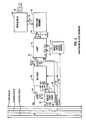
- Fig. 1 is a schematic illustration of the system for monitoring presence and use of EDP equipment, depicting a host system and plurality of remote machines with a power bus communication link.
- Fig. 2 is a functional block diagram of the hardware associated with each of the host and remote computer systems of Fig. 1 for effecting the system intercommunication of the invention.
- Fig. 3 is a functional block diagram of a computer program executed by a remote system of Fig. 1 on power-up.
- Fig. 4 is a functional block diagram of a next computer program executed by a remote system of Fig. 1 in response to an incoming interrogative message from the host computer.
- Fig. 5 is a functional block diagram of a computerized control program executed by the host system of Fig. 1.
- the system 10 is comprised of a central monitoring computer 12 and one or more representative remote electronic data processing machines 28, 30, 32, 34, 36 and 38.
- the invention is not intended to be limited to any particular type of host or remote computer, and, thus, admits to the application with personal computers, workstations and even mini computers or the like, such as that depicted at reference numeral 38.
- the central monitoring computer 12 generally serves the purpose of maintaining control and a database of information on all the other machines in the system 10, as will hereinafter be described in greater detail, including which computers are deployed in various uses throughout a given building, for example.
- the remote systems 28, 30, 32, 34, 36 and 38 receive power, as does the host system 12, via a common conventional 110 volt AC power bus 14, as represented by connections 17, 19, 21, 23, 25 and 27 to the remote systems and interconnections 18, 20, 22, 24 and 26 to the host system 12, such power conventionally being delivered through appropriate power transformers well known in the art.
- the system of the present invention alleviates the cost associated with cabling a network with specialized dedicated cabling using traditional LAN cabling or the like.
- FIG. 2 depicted therein is the hardware provided with each remote and host system in order to implement the aforementioned power line communication.
- the device depicted in Fig. 2 with respect to a given remote or host computer of Fig. 1 is attached to the particular computer bus (which conventionally includes a data, address and control bus lines 40, 42 and 44, respectively) via an I/O port 56.
- this I/O port may be implemented by a digital integrated circuit, such as a Motorola 6820 chip or the equivalent.
- This port 56 allows data, represented by arrow 48 and 64, to be transferred to and from the port 56 by using typical INP (ADDR) and OUT (ADDR) commands or equivalents well known in the art.
- the hardware communication device of Fig. 2 may be configured to interrupt the microprocessor of the given remote computer in the event of an incoming message, or, in the alternative, a simple polling scheme may be substituted.
- Selection logic 52 in response to address commands 50 from the particular computer, will generate chip select signals 54 and 68 for controlling the functions of the hardware system of Fig. 2 in a conventional manner.
- buffered bidirectional data flows in and out of the I/O port 56 to a uniform asynchronous receiver-transmitter or UART 70 such as an integrated circuit INTEL 8251 manufactured by the INTEL Corporation, or, in the alternative, some other serial/parallel conversion device as desired.
- a uniform asynchronous receiver-transmitter or UART 70 such as an integrated circuit INTEL 8251 manufactured by the INTEL Corporation, or, in the alternative, some other serial/parallel conversion device as desired.
- the microprocessor associated with the computer containing the Fig. 2 hardware will generate on the control bus 44 from time-to-time read-write signals 66 and clock signals 64 generating conventional read or write commands as required and for controlling the transmission and receiving rate of the system.
- a BAUD rate generator 62 receives this computer clock signal 60 and generates receive and transmit signals 72 delivered to the UART 70 for controlling the rate at which the digitized signals imposed on the power line 84 are transmitted or received.
- Outgoing serial messages generated by the computer are delivered on the transmission line 74 to a power line modem 78 which modulates them as shown by line 82 onto the power supply 80 of the particular computer and, thence, onto the power line 84 to which the computer is plugged in.
- incoming data on the power line 84 is routed to the power supply 80 and delivered on line 82 to the power line modem 78 wherein these signals are decoded, and delivered on the asynchronous receive line 76 to the UART 70.
- the power line modem may take the form of a NE5050 integrated circuit power line modem manufactured by the Signetics corporation or equivalent.
- the system provided herein is accordingly far superior to a system requiring establishment of a LAN and interconnection of each remote machine thereto.
- this approach is impractical due to prohibitive costs of cabling every machine in a building together.
- such an approach does not guarantee that an unconnected machine is not being used somewhere in the building.
- yet another problem with this approach arises when a machine configured as a public resource on the LAN becomes prey to anyone attempting to breach security.
- Fig. 3 software in a representative remote computer will consist of essentially two routines.
- the first, as shown in Fig. 3, is preferably entered and executed immediately after the computer is powered up and has executed a power on self-test routine or "POST".
- POST power on self-test routine
- FIG. 3 shows a routine prompting the user for a unique user I.D. as shown at block 94.
- the remote computer program will then preferably execute a sub-routine transmitting the thus prompted-for user I.D. and a unique machine identification code to the central monitoring computer 12 via the power line modem of Fig. 2 in the manner previously described.
- This step of machine and user I.D. transmission is shown in Fig. 3 at block 96.
- each remote computer may preferably have stored therein in BIOS, other ROM, in DASDI or the like, a unique identifying number associated with that particular remote computer.
- the particular remote computer may fetch from the known stored location this unique machine I.D. for modulation onto the power line.
- the routine executed on the remote computers will preferably pass control back to the operating system allowing normal use of the remote computer, as shown at block 98.
- the aforementioned second routine desirably executed by each remote control system is entered into in response to an incoming poll or interrupt from the central monitoring computer 12 via the power line.
- This incoming poll or interrupt interrogative from the host is schematically depicted in Fig. 4 at block 100.
- the correlative remote computer Upon decoding of this command off of the power line by the hardware of Fig. 2, the correlative remote computer, in response thereto, will derive and modulate onto the power line its respective machine and user I.D.'s, which were stored previously, for subsequent transmission to the central monitor 12.
- This program execution step is shown at block 102 of Fig. 4 whereupon control returns to the operating software, 104.
- routines may be burned into ROM of the representative remote computer or, in the alternative, embedded in the operating system or stored on DASDI as hidden files.
- ROM read only memory
- DASDI embedded in the operating system
- Fig. 5 depicted therein is a schematic functional block diagram of a computer program executed by the host system 12 for effecting the objects of the present invention.
- the central monitoring computer 12 in response to software control implementing the functional steps of Fig. 5, will monitor all power circuits to which remote computers, which are to be monitored, are connected for incoming messages from these computers.
- the host monitor 12 will also perform numerous additional functions to be hereinafter described, including the updating of its database or remote machines from the information contained in these incoming messages from the remote machine.
- the host computer 12 in response to program control, will provide functions allowing the operator to query the database for various items as will be described with reference to Fig. 5.
- the computer program executing on the host system 12 will commence as shown at block 106 whereupon the lines 18-26, Fig. 1, will be monitored by the host 12 for incoming signals as shown generally at blocks 108, 110 and 112. Upon receipt of incoming data from each respective remote computer regarding the machine and user I.D.'s, the host computer 12 will update an appropriate database 114 with this data. The host system operator may then interact with the host, as shown at block 116, to select any number of a plurality of functions to be performed by the remote system 12 in response to this user input, which is gererally shown at reference numeral 118.
- These tasks performable by the host system relating to the management of remote EDP systems include the choices of querying the database for machines which are currently in use, 120, querying the database for machines which have not been used for a specified period of time, 124, querying the database for a specific machine I.D. to determine that machine's status, 126, querying the database for a specific user I.D., for example, to determine which machine a user is accessing, 128, and a choice to exit a routine for maintenance, 130.
- these interactive usages of this data as generally shown at 118 of Fig. 5, are not intended to be so limited to only those functions depicted with reference to reference numerals 120-130. In other words, the invention lends itself to any number of applications of this data, and, thus, is not intended to be limited to only those described herein.
- any necessary polls in response thereto are generated by the host computer 12 and modulated onto the power line, as shown at block 132.
- these polls could, if desired, include not only commands to a particular remote computer to send back its machine and user I.D.'s, but could further be used for purposes of providing additional data or control to the selected remote computer.
- the operating software of the host system 12 will query at 134 whether it is desirable to exit the auditing routine. If the answer is affirmative, as shown at path 138, control will be returned at 140 to the operating system for further normal usage of the host 12.
- control routes through path 136 to continue the just-described cycle indefinitely, e.g. namely monitoring the various power lines and interacting with the data obtained therefrom.
Landscapes
- Engineering & Computer Science (AREA)
- Theoretical Computer Science (AREA)
- Computing Systems (AREA)
- Physics & Mathematics (AREA)
- Quality & Reliability (AREA)
- General Engineering & Computer Science (AREA)
- General Physics & Mathematics (AREA)
- Mathematical Physics (AREA)
- Debugging And Monitoring (AREA)
- Remote Monitoring And Control Of Power-Distribution Networks (AREA)
- Power Sources (AREA)
Applications Claiming Priority (2)
| Application Number | Priority Date | Filing Date | Title |
|---|---|---|---|
| US07/520,578 US5072370A (en) | 1990-05-08 | 1990-05-08 | System and method for monitoring electronic data processing equipment |
| US520578 | 1990-05-08 |
Publications (2)
| Publication Number | Publication Date |
|---|---|
| EP0456395A2 true EP0456395A2 (fr) | 1991-11-13 |
| EP0456395A3 EP0456395A3 (en) | 1993-09-01 |
Family
ID=24073217
Family Applications (1)
| Application Number | Title | Priority Date | Filing Date |
|---|---|---|---|
| EP19910303842 Withdrawn EP0456395A3 (en) | 1990-05-08 | 1991-04-26 | System and method for monitoring electronic data processing equipment |
Country Status (3)
| Country | Link |
|---|---|
| US (1) | US5072370A (fr) |
| EP (1) | EP0456395A3 (fr) |
| JP (1) | JPH077368B2 (fr) |
Cited By (4)
| Publication number | Priority date | Publication date | Assignee | Title |
|---|---|---|---|---|
| EP0585154A3 (en) * | 1992-07-31 | 1994-06-29 | Sextant Avionique | Device for the dynamic display of information about an electronic system with a variable configuration and/or composition |
| GB2287558A (en) * | 1994-03-15 | 1995-09-20 | Fujitsu Ltd | Computer network supervision |
| WO1996009613A1 (fr) * | 1994-09-19 | 1996-03-28 | Hedstroem Mats Holger Goeran | Systeme de commande et d'enregistrement |
| WO1997020295A1 (fr) * | 1995-11-28 | 1997-06-05 | Rolf Edman | Systeme de commande et/ou d'enregistrement |
Families Citing this family (41)
| Publication number | Priority date | Publication date | Assignee | Title |
|---|---|---|---|---|
| GB2249460B (en) * | 1990-09-19 | 1994-06-29 | Intel Corp | Network providing common access to dissimilar hardware interfaces |
| US5452344A (en) * | 1992-05-29 | 1995-09-19 | Datran Systems Corporation | Communication over power lines |
| JPH0612288A (ja) * | 1992-06-29 | 1994-01-21 | Hitachi Ltd | 情報処理システム及びその監視方法 |
| US5640513A (en) * | 1993-01-22 | 1997-06-17 | International Business Machines Corporation | Notification of disconnected service machines that have stopped running |
| AU6408294A (en) * | 1993-03-16 | 1994-10-11 | Ht Research, Inc. | A chassis for a multiple computer system |
| US5694595A (en) * | 1993-12-23 | 1997-12-02 | International Business Machines, Corporation | Remote user profile management administration in a computer network |
| US5864698A (en) * | 1994-08-24 | 1999-01-26 | Packard Bell Nec | Disk based bios |
| US5491791A (en) * | 1995-01-13 | 1996-02-13 | International Business Machines Corporation | System and method for remote workstation monitoring within a distributed computing environment |
| US6112237A (en) * | 1996-11-26 | 2000-08-29 | Global Maintech, Inc. | Electronic monitoring system and method for externally monitoring processes in a computer system |
| SE521041C2 (sv) | 1997-05-28 | 2003-09-23 | Ericsson Telefon Ab L M | Metod för optimering av transaktionsprotokoll inom en distribuerad databas |
| US6529932B1 (en) | 1998-04-01 | 2003-03-04 | Microsoft Corporation | Method and system for distributed transaction processing with asynchronous message delivery |
| US6205498B1 (en) * | 1998-04-01 | 2001-03-20 | Microsoft Corporation | Method and system for message transfer session management |
| US6311291B1 (en) * | 1998-08-12 | 2001-10-30 | Pc-Tel, Inc. | Remote modem control and diagnostic system and method |
| US7486648B1 (en) * | 1999-10-11 | 2009-02-03 | Park Tours, Inc. | Wireless extension of local area networks |
| US20070178912A1 (en) * | 2000-03-14 | 2007-08-02 | Robert Baranowski | System and method for enhancing user experience in a wide-area facility having a distributed, bounded environment |
| US7073083B2 (en) | 2001-07-18 | 2006-07-04 | Thomas Licensing | Method and system for providing emergency shutdown of a malfunctioning device |
| JP2003172578A (ja) * | 2001-12-07 | 2003-06-20 | Hitachi Ltd | ネットワーク対応家電機器、家電機器点検システム及び家電機器点検サービス |
| JP4149240B2 (ja) * | 2002-07-16 | 2008-09-10 | シャープ株式会社 | 電気機器の管理方法、管理装置、そのプログラム、および、電気機器の管理システム |
| KR100505230B1 (ko) * | 2002-12-10 | 2005-08-03 | 엘지전자 주식회사 | 홈네트워크 시스템 및 그 제품 삭제방법 |
| US7424525B2 (en) * | 2003-06-30 | 2008-09-09 | Microsoft Corporation | Managing headless computer systems |
| US8543566B2 (en) | 2003-09-23 | 2013-09-24 | Salesforce.Com, Inc. | System and methods of improving a multi-tenant database query using contextual knowledge about non-homogeneously distributed tenant data |
| US7529728B2 (en) | 2003-09-23 | 2009-05-05 | Salesforce.Com, Inc. | Query optimization in a multi-tenant database system |
| US7779039B2 (en) | 2004-04-02 | 2010-08-17 | Salesforce.Com, Inc. | Custom entities and fields in a multi-tenant database system |
| ITMI20050677A1 (it) * | 2005-04-18 | 2006-10-19 | Sisvel Spa | Sistema di collegamento tra un centro servizi ed una pluralita' di dispositivi di ricezione televisiva |
| US20070055740A1 (en) * | 2005-08-23 | 2007-03-08 | Luciani Luis E | System and method for interacting with a remote computer |
| WO2007030796A2 (fr) | 2005-09-09 | 2007-03-15 | Salesforce.Com, Inc. | Systemes et procedes d'exportation, de publication, de navigation et d'installation d'applications sur demande dans un environnement de base de donnees a plusieurs detenteurs |
| US8387138B2 (en) | 2006-03-21 | 2013-02-26 | At&T Intellectual Property I, L.P. | Security scanning system and method |
| US9361366B1 (en) | 2008-06-03 | 2016-06-07 | Salesforce.Com, Inc. | Method and system for controlling access to a multi-tenant database system using a virtual portal |
| US8473518B1 (en) | 2008-07-03 | 2013-06-25 | Salesforce.Com, Inc. | Techniques for processing group membership data in a multi-tenant database system |
| US8473469B1 (en) | 2008-08-25 | 2013-06-25 | Salesforce.Com, Inc. | Techniques for implementing batch processing in a multi-tenant on-demand database system |
| US8296321B2 (en) * | 2009-02-11 | 2012-10-23 | Salesforce.Com, Inc. | Techniques for changing perceivable stimuli associated with a user interface for an on-demand database service |
| US10482425B2 (en) | 2009-09-29 | 2019-11-19 | Salesforce.Com, Inc. | Techniques for managing functionality changes of an on-demand database system |
| US8443366B1 (en) | 2009-12-11 | 2013-05-14 | Salesforce.Com, Inc. | Techniques for establishing a parallel processing framework for a multi-tenant on-demand database system |
| US8776067B1 (en) | 2009-12-11 | 2014-07-08 | Salesforce.Com, Inc. | Techniques for utilizing computational resources in a multi-tenant on-demand database system |
| US9189090B2 (en) | 2010-03-26 | 2015-11-17 | Salesforce.Com, Inc. | Techniques for interpreting signals from computer input devices |
| US8977675B2 (en) | 2010-03-26 | 2015-03-10 | Salesforce.Com, Inc. | Methods and systems for providing time and date specific software user interfaces |
| US8595181B2 (en) | 2010-05-03 | 2013-11-26 | Salesforce.Com, Inc. | Report preview caching techniques in a multi-tenant database |
| US8977739B2 (en) | 2010-05-03 | 2015-03-10 | Salesforce.Com, Inc. | Configurable frame work for testing and analysis of client-side web browser page performance |
| US8972431B2 (en) | 2010-05-06 | 2015-03-03 | Salesforce.Com, Inc. | Synonym supported searches |
| US8819632B2 (en) | 2010-07-09 | 2014-08-26 | Salesforce.Com, Inc. | Techniques for distributing information in a computer network related to a software anomaly |
| US9069901B2 (en) | 2010-08-19 | 2015-06-30 | Salesforce.Com, Inc. | Software and framework for reusable automated testing of computer software systems |
Family Cites Families (11)
| Publication number | Priority date | Publication date | Assignee | Title |
|---|---|---|---|---|
| US3702460A (en) * | 1971-11-30 | 1972-11-07 | John B Blose | Communications system for electric power utility |
| US4218738A (en) * | 1978-05-05 | 1980-08-19 | International Business Machines Corporation | Method for authenticating the identity of a user of an information system |
| US4484271A (en) * | 1979-01-31 | 1984-11-20 | Honeywell Information Systems Inc. | Microprogrammed system having hardware interrupt apparatus |
| US4357605A (en) * | 1980-04-08 | 1982-11-02 | Metallurgical Research, Inc. | Cash flow monitoring system |
| GB2083301B (en) * | 1980-09-01 | 1984-09-26 | South Eastern Elec Board | Method of and apparatus for controlling loads on an electrical power supply |
| US4540890A (en) * | 1982-05-24 | 1985-09-10 | Galber Automazione E | System for selectively addressing electrical control signals from a control unit to a plurality of remote units |
| GB8511758D0 (en) * | 1985-05-09 | 1985-06-19 | Emi Ltd | Data communications systems |
| JPS6249466A (ja) * | 1985-08-28 | 1987-03-04 | Nec Corp | 利用者端末管理方式 |
| JPS62190948A (ja) * | 1986-02-18 | 1987-08-21 | Nisshin Sangyo Kk | 電力線搬送を使用したコンピユ−タネツトワ−クシステム |
| JPS63196197A (ja) * | 1987-02-09 | 1988-08-15 | Toshiba Heating Appliances Co | 電力線搬送制御システム |
| GB2229025A (en) * | 1989-03-09 | 1990-09-12 | Elocktronics Limited | Safeguarding electrical apparatus |
-
1990
- 1990-05-08 US US07/520,578 patent/US5072370A/en not_active Expired - Fee Related
-
1991
- 1991-04-26 JP JP3123126A patent/JPH077368B2/ja not_active Expired - Lifetime
- 1991-04-26 EP EP19910303842 patent/EP0456395A3/en not_active Withdrawn
Cited By (6)
| Publication number | Priority date | Publication date | Assignee | Title |
|---|---|---|---|---|
| EP0585154A3 (en) * | 1992-07-31 | 1994-06-29 | Sextant Avionique | Device for the dynamic display of information about an electronic system with a variable configuration and/or composition |
| GB2287558A (en) * | 1994-03-15 | 1995-09-20 | Fujitsu Ltd | Computer network supervision |
| GB2287558B (en) * | 1994-03-15 | 1998-03-11 | Fujitsu Ltd | Supervising system in a computer network |
| US5748880A (en) * | 1994-03-15 | 1998-05-05 | Fujitsu Limited | Computer-supervising system |
| WO1996009613A1 (fr) * | 1994-09-19 | 1996-03-28 | Hedstroem Mats Holger Goeran | Systeme de commande et d'enregistrement |
| WO1997020295A1 (fr) * | 1995-11-28 | 1997-06-05 | Rolf Edman | Systeme de commande et/ou d'enregistrement |
Also Published As
| Publication number | Publication date |
|---|---|
| EP0456395A3 (en) | 1993-09-01 |
| JPH04229349A (ja) | 1992-08-18 |
| US5072370A (en) | 1991-12-10 |
| JPH077368B2 (ja) | 1995-01-30 |
Similar Documents
| Publication | Publication Date | Title |
|---|---|---|
| EP0456395A2 (fr) | Système et procédé de surveillance d'équipement de traitement de données électroniques | |
| CA2325712C (fr) | Systeme de marquage par identification radiofrequence de biens en reseau | |
| EP0520766B1 (fr) | Surveillance de bus pour l'administrateur d'un système à ordinateur | |
| EP0520769B1 (fr) | Gestionnaire de système d'ordinateur | |
| US5684957A (en) | Network management system for detecting and displaying a security hole | |
| US7322048B2 (en) | Control device for a computer and a computer comprising such a control device | |
| CA1246747A (fr) | Appareil pour controler l'utilisation de logiciels | |
| US6708297B1 (en) | Method and system for monitoring errors on field replaceable units | |
| TW343301B (en) | An information security system for tracing the information outflow and a method for tracing the same | |
| CN108408362A (zh) | 一种用于输送带的智能传输监控系统及监控方法 | |
| CN120880811B (zh) | 基于工业互联网标识编码的主动标识方法以及装置 | |
| CN113888065A (zh) | 一种u位级设备监控方法、系统、装置和计算机设备 | |
| US6315198B1 (en) | Key cabinet for equipping an access control system and access control method and system using this key cabinet | |
| KR101901644B1 (ko) | Usim 관리 장치 및 모니터링 프로그램 | |
| US4654638A (en) | Security monitoring system | |
| JPH09179828A (ja) | 訃算機ネツトワークにおける利用者の割当て装置 | |
| CN111428220A (zh) | 一种基于远程协同平台的移动终端办公系统 | |
| CN113939046A (zh) | 一种基于5g通信的疫情防控终端及使用方法 | |
| CN120234841B (zh) | 服务器、数据交互方法、设备、存储介质和程序产品 | |
| CN112272160B (zh) | 一种主机安全信息调取方法、系统、智能终端及计算机存储介质 | |
| CN120410408A (zh) | 一种计量资产的资产管理系统 | |
| CN110677412A (zh) | 一种数据下载的网络安全防护方法及装置 | |
| JPS615305A (ja) | 製造用の制御システム | |
| KR100651345B1 (ko) | 분산형 제어시스템의 데이터 저장시스템 | |
| CN116962072A (zh) | 电力调度数据网的二次安全防护设备的自动化运维方法 |
Legal Events
| Date | Code | Title | Description |
|---|---|---|---|
| PUAI | Public reference made under article 153(3) epc to a published international application that has entered the european phase |
Free format text: ORIGINAL CODE: 0009012 |
|
| AK | Designated contracting states |
Kind code of ref document: A2 Designated state(s): DE FR GB |
|
| 17P | Request for examination filed |
Effective date: 19911219 |
|
| PUAL | Search report despatched |
Free format text: ORIGINAL CODE: 0009013 |
|
| AK | Designated contracting states |
Kind code of ref document: A3 Designated state(s): DE FR GB |
|
| STAA | Information on the status of an ep patent application or granted ep patent |
Free format text: STATUS: THE APPLICATION IS DEEMED TO BE WITHDRAWN |
|
| 18D | Application deemed to be withdrawn |
Effective date: 19931102 |