EP0456397B1 - Système séquentiel pour puits avec contrôle à distance pour libérer des bouchons - Google Patents
Système séquentiel pour puits avec contrôle à distance pour libérer des bouchons Download PDFInfo
- Publication number
- EP0456397B1 EP0456397B1 EP91303867A EP91303867A EP0456397B1 EP 0456397 B1 EP0456397 B1 EP 0456397B1 EP 91303867 A EP91303867 A EP 91303867A EP 91303867 A EP91303867 A EP 91303867A EP 0456397 B1 EP0456397 B1 EP 0456397B1
- Authority
- EP
- European Patent Office
- Prior art keywords
- valve
- plug
- port
- sequencing
- plug release
- Prior art date
- Legal status (The legal status is an assumption and is not a legal conclusion. Google has not performed a legal analysis and makes no representation as to the accuracy of the status listed.)
- Expired - Lifetime
Links
- 238000012163 sequencing technique Methods 0.000 claims description 73
- 239000004020 conductor Substances 0.000 claims description 51
- 239000012530 fluid Substances 0.000 claims description 23
- 239000004568 cement Substances 0.000 description 9
- 241000282472 Canis lupus familiaris Species 0.000 description 6
- 230000001276 controlling effect Effects 0.000 description 6
- 238000005553 drilling Methods 0.000 description 4
- 230000004913 activation Effects 0.000 description 3
- 238000000034 method Methods 0.000 description 3
- 230000004044 response Effects 0.000 description 3
- 239000002002 slurry Substances 0.000 description 3
- IJGRMHOSHXDMSA-UHFFFAOYSA-N Atomic nitrogen Chemical compound N#N IJGRMHOSHXDMSA-UHFFFAOYSA-N 0.000 description 2
- 238000004140 cleaning Methods 0.000 description 2
- 230000008878 coupling Effects 0.000 description 2
- 238000010168 coupling process Methods 0.000 description 2
- 238000005859 coupling reaction Methods 0.000 description 2
- 238000010586 diagram Methods 0.000 description 2
- 239000004519 grease Substances 0.000 description 2
- 230000001105 regulatory effect Effects 0.000 description 2
- 239000004677 Nylon Substances 0.000 description 1
- 238000004891 communication Methods 0.000 description 1
- 239000007789 gas Substances 0.000 description 1
- 231100001261 hazardous Toxicity 0.000 description 1
- 239000007788 liquid Substances 0.000 description 1
- 230000001050 lubricating effect Effects 0.000 description 1
- 230000013011 mating Effects 0.000 description 1
- 230000007246 mechanism Effects 0.000 description 1
- 210000002445 nipple Anatomy 0.000 description 1
- 229910052757 nitrogen Inorganic materials 0.000 description 1
- 229920001778 nylon Polymers 0.000 description 1
- 239000003129 oil well Substances 0.000 description 1
- 230000008569 process Effects 0.000 description 1
- 230000001681 protective effect Effects 0.000 description 1
- 238000005086 pumping Methods 0.000 description 1
- 230000000717 retained effect Effects 0.000 description 1
- 238000000926 separation method Methods 0.000 description 1
- 229910001220 stainless steel Inorganic materials 0.000 description 1
- 239000010935 stainless steel Substances 0.000 description 1
- XLYOFNOQVPJJNP-UHFFFAOYSA-N water Substances O XLYOFNOQVPJJNP-UHFFFAOYSA-N 0.000 description 1
Images


Classifications
-
- F—MECHANICAL ENGINEERING; LIGHTING; HEATING; WEAPONS; BLASTING
- F15—FLUID-PRESSURE ACTUATORS; HYDRAULICS OR PNEUMATICS IN GENERAL
- F15B—SYSTEMS ACTING BY MEANS OF FLUIDS IN GENERAL; FLUID-PRESSURE ACTUATORS, e.g. SERVOMOTORS; DETAILS OF FLUID-PRESSURE SYSTEMS, NOT OTHERWISE PROVIDED FOR
- F15B21/00—Common features of fluid actuator systems; Fluid-pressure actuator systems or details thereof, not covered by any other group of this subclass
- F15B21/001—Servomotor systems with fluidic control
-
- E—FIXED CONSTRUCTIONS
- E21—EARTH OR ROCK DRILLING; MINING
- E21B—EARTH OR ROCK DRILLING; OBTAINING OIL, GAS, WATER, SOLUBLE OR MELTABLE MATERIALS OR A SLURRY OF MINERALS FROM WELLS
- E21B33/00—Sealing or packing boreholes or wells
- E21B33/02—Surface sealing or packing
- E21B33/03—Well heads; Setting-up thereof
- E21B33/04—Casing heads; Suspending casings or tubings in well heads
- E21B33/05—Cementing-heads, e.g. having provision for introducing cementing plugs
-
- E—FIXED CONSTRUCTIONS
- E21—EARTH OR ROCK DRILLING; MINING
- E21B—EARTH OR ROCK DRILLING; OBTAINING OIL, GAS, WATER, SOLUBLE OR MELTABLE MATERIALS OR A SLURRY OF MINERALS FROM WELLS
- E21B34/00—Valve arrangements for boreholes or wells
- E21B34/16—Control means therefor being outside the borehole
Definitions
- the present invention relates generally to sequential remote control plug release systems, for use in oil wells or the like.
- cementing plugs are usually stored in a plug container on top of the casing at the well head.
- a bar or other means supports a plug in the plug container until the appropriate time for releasing the plug. The bar is then removed, thereby allowing the plug to drop into the casing.
- Various levers and rods have been proposed for temporarily retaining a plug in the plug container.
- a particular embodiment of plug container includes two plugs, held by two plug release plungers, and three fluid inlets, connected through manifold valves to a manifold through which the cement and drilling mud or fluids are pumped.
- the plug release plungers and the manifold valves must be operated to release the plugs and admit the fluids at the proper times. They can be manually operated by an operator at the plug container, or more preferably they can be operated remotely from the well head where the container is attached. Improved safety, enhanced convenience, and automated control "on the fly" are some of the reasons why remote control is preferred.
- US-A-4782894 discloses a sequential remote control plug release system, which comprises a plug container having a chamber for receiving two cementing plugs; a first plug release plunger, connected to said plug container so that said first plug release plunger can be extended into said chamber to support a lower cementing plug received in said chamber and further so that said first plug release plunger can be retracted out of said chamber to allow the lower cementing plug to drop; a second plug release plunger, connected to said plug container so that said second plug release plunger can be extended into said chamber to support an upper cementing plug received in said chamber and further so that said second plug release plunger can be retracted out of said chamber to allow the upper cementing plug to drop; a first manifold valve connected to said plug container below said first plug release plunger; a second manifold valve connected to said plug container in between said first and second plug release plungers; remote control means, adapted to be operated at a location spaced remotely from said plug container, for controlling the retracting of said first and second plug release plungers and the opening
- the present invention is mainly characterized in that the said system further comprises: a third manifold valve connected to said plug container above said second release plunger; the said remote control means having a fifth valve means for providing an actuating signal; for controlling the opening of the said third manifold valve and a fifth conductor means for conducting said actuating signal for said third manifold valve to said third manifold valve; and sequencing means, connected to said second, third, fourth and fifth valve means and said second, third, fourth and fifth conductor means, for preventing said actuating signal for said second manifold valve from opening said second manifold valve through said third conductor means until after said actuating signal for said first plug release plunger is provided through said second conductor means to retract said first plug release plunger, and for preventing said actuating signal for said second plug release plunger from retracting said second plug release plunger through said fourth conductor means until after said actuating signal for said second manifold valve is provided through
- This system allows activation of plug release plungers and manifold valves from a remote location, such as from the rig floor. Sequencing is provided to prevent the operator from accidentally releasing an upper plug before a lower plug or from opening the wrong manifold valve.
- the present invention is particularly suitable when stacking single plug containers or using double plug containers having two plungers and three manifold valves; however, the present invention can be adapted for use with other plug container configurations.
- the remote control means incorporated in the present invention enables the operator to control the plug release and fluid inlet functions from a safer environment than immediately at the well head where the plug container is located.
- the system allows the manifold valves to be closed at any time, such as if an emergency arises; and once the predetermined sequence has been followed, the manifold valves can be opened and closed in any order to facilitate cleaning, for example.
- fluid pressure conducting hoses which connect the plug container to the remote location can be bundled in groups of two or four hoses, for example, and have end connectors of different sizes and separations keyed to prevent erroneous make-up of the system.
- a sequential remote control plug release system of the present invention includes a plug container 20 connected to a remote sequencer 22 by control signal conductors 24.
- the plug container 20 is connected in a known manner to well head equipment 26 at the mouth of a well 27.
- the remote sequencer 22 is at a location remote from the well, such as on the floor of a rig above the well head.
- the plug container 20 of a particular embodiment includes a chamber 28 for receiving two conventional cementing plugs, such as a lower five-wiper plug 30 and an upper top plug 32.
- a plug release plunger 34 is connected to the plug container 20 in a known manner so that the plug release plunger 34 can be extended into the chamber 28 to support the lower cementing plug 30 and further so that the plug release plunger 34 can be retracted out of the chamber 28 to allow the cementing plug 30 to drop into the well 27.
- a plug release plunger 36 is connected to the plug container 20 above the plug release plunger 34 so that the plug release plunger 36 can be extended into the chamber 28 to support the upper cementing plug 32 and further so that the plug release plunger 36 can be retracted out of the chamber 28 to allow the upper cementing plug to drop into the well 27.
- the plug container 20 depicted in FIG. 1 also includes three fluid inlets to which three manifold valves, modified with actuators, 38, 40, 42 are connected.
- the manifold valve 38 is connected to the plug container 20 below the plug release plunger 34; the manifold valve 40 is connected to the plug container 20 in between the two plug release plungers 34, 36; and the manifold valve 42 is connected to the plug container 20 above the plug release plunger 36 as illustrated in FIG. 1.
- the valves 38, 40, 42 are manifolded and connected to a fluid source 44 which in the specific implementation referred to herein provides cement slurry, drilling mud and other fluids used in a cementing job where something, such as a casing, is to be cemented into the well 27.
- valves 38, 40, 42, including actuators, used in the preferred embodiments described herein are LO TORQ plug valves with actuators which can deliver 5000 inch-pounds (565 Nm) of torque with 125 psi (0.86 MPa) air pressure. These have manual override capability which can be locally operated if needed.
- the plug release plungers 34, 36 are designed to lock mechanically in their extended positions to help prevent internal pressure from the well from retracting the plungers.
- the mechanical lock releases when actuating pressure is supplied to retract the respective plug release plunger.
- the plug release plungers may be operated manually if the actuating pressure supply fails. By retracting a locking sleeve using manual override handles which are provided, the operator frees the plunger so that it can be retracted from the chamber 28.
- the locking sleeve is spring-loaded and must be retracted fully to release the plunger in the preferred embodiment.
- plug release plungers 34, 36 is similar to the type of plug release plunger disclosed in U.S. Patent 3,322,197 to which reference should be made for details. A general description of a particular embodiment will be given with reference to FIG. 2.
- Each plug release plunger 34, 36 of the preferred embodiment includes a body 46 having an open end of a cavity 47 which receives a mandrel 48 having a threaded nipple 50 for screwing into a mating opening of the plug container 20 which has a cylindrical outer sleeve.
- a plunger or plug retaining arm 52 Slidably disposed within the body 46 and mandrel 48 is a plunger or plug retaining arm 52.
- the forward end 54 of the arm 52 extends into and retracts from the chamber 28 of the plug container 20.
- a rearward end 56 of the arm 52 receives an eye bolt 58 which can be grasped and pulled to manually move the retaining arm 52.
- the retaining arm 52 In its extended position shown in FIG. 2, the retaining arm 52 is locked by locking dogs 60, 62 which are longitudinally retained between an inner support sleeve 64 and the mandrel 48.
- the dogs 60, 62 are held or fixed radially in engagement with the retaining arm 52 by a piston 66 biased to a rightward position (as viewed in FIG. 2) by a spring 68.
- the spring 68 can itself be biased or compressed by an annular piston 69 slidably disposed around the sleeve 64.
- the piston 69 is received in an annular spring receptacle or cavity 71 defined between the body 46 and the sleeve 64.
- Handles 70, 72 connect to the piston 66 so that an operator can grasp the handles and retract the piston 66 to release the locking dogs 60, 62 manually if needed.
- the piston 66 is moved to a leftward position as viewed in FIG. 2 to release or free the locking dogs 60, 62 in response to the application of a pressurized fluid signal received through a port 74.
- the received pressurized signal also acts against a surface of an enlarged piston portion 76 of the retaining arm 52 to move the retaining arm 52 to the left as viewed in FIG. 2, which retracts the forward end 54 of the retaining arm 52 from the chamber 28 of the plug container 20.
- a pressurized fluid signal is communicated to a port 78 near the rear of the plug release plunger body 46 to act oppositely against the piston 76.
- a pressurized fluid through the port 78 also acts through a channel 79 on the piston 69 to urge it against the spring 68 for insuring that the locking dog retaining piston 66 holds the locking dogs 60, 62 in place.
- the channel 79 also communicates with the cavity 47 through the radial passage from port 78.
- a protective shield 80 which covers the rearward end of the retaining arm 52 when it is retracted.
- a grease fitting 82 mounted in a recess of the mandrel 48 allows for lubricating grease to be added as needed.
- the remote sequencer 22 provides remote control means, adapted to be operated at a location spaced remotely from the plug container 20, for controlling the retracting of the plug release plungers 34, 36 and the opening of the manifold valves 38, 40, 42.
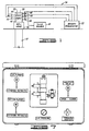
- the remote sequencer 22 of the preferred embodiment includes an operator console or control panel 84 having two exterior views shown in FIGS. 3 and 4.
- the console 84 includes a sequencing apparatus to help prevent activation of a plug release plunger or manifold valve at the wrong time. The operator must follow the correct sequence of releasing plugs and opening manifold valves; otherwise, the console will ignore the operator's actions directed to releasing the plugs or opening the manifold valves.
- all manifold valves can be closed at any time irrespective of the predetermined sequencing so that the inlet openings of the plug container 20 connected to the manifold can be closed in case trouble arises, for example.
- the console 84 includes a stainless steel enclosure or housing 86 with a key-locked panel door (not shown). When closed, the panel door seals to keep out moisture and debris. Opening the door reveals a front panel 88 containing a schematic illustration 90 of the double plug container 20 with the two plug release plungers 34, 36 and the three manifold valves 38, 40, 42.
- Valve operating handles 92, 94, 96, 98, 100 are positioned beside the schematically represented plug release plungers 34, 36 and manifold valves 38, 40, 42, respectively.
- the handles 92, 94, 96, 98, 100 connect to actuating valves disposed within the housing 86 as will be further described hereinbelow.
- a pressure gauge 102 which registers actuating fluid pressure regulated within the console. Also shown in FIG. 3 is a handle 104 which is connected to a subsequently described pressure shut off valve.
- a side panel 106 extending perpendicular to the front panel 88 is shown.
- Six pairs of connectors are mounted through the side panel 106.
- the internal portions of the connectors connect to portions of the sequencing apparatus contained within the housing 86, and the external portions of the connectors connect to the conductors 24 schematically illustrated in FIG. 1 (except for the lowermost pair of connectors 108, 110, which connector 108 connects to a pressurized fluid source and which connector 110 connects to an exhaust line or simply provides an exhaust port).
- a pair of connectors 112, 114 are connected through a pair of hoses of the conductors 24 to the ports 74, 78 of the plug release plunger 36; a pair of connectors 116, 118 connect through a respective pair of hoses of the conductors 24 to the ports 74, 78 of the plug release plunger 34; a pair of connectors 120, 122 connect through a respective pair of hoses to the actuator of the top manifold valve 42; a pair of connectors 124, 126 connect through a respective pair of hoses of the conductors 24 to the actuator of the middle manifold valve 40; and a pair of conductors 128, 130 connect through a respective pair of hoses of the conductors 24 to the actuator of the bottom manifold valve 38.
- the connectors within each of the pairs of the connectors 112-130 are spaced different distances apart. As shown in FIG. 4, the connectors 112, 114 are the closest, with progressively wider spacing for the subsequent pairs of connectors through the pair of connectors 128, 130. Each of these distances or spacings is different to provide a key which must be matched by a respective pair of hoses of the conductors 24 to facilitate correct connections being made. Thus each respective pair of hoses connected to these pairs of connectors is keyed to the spacing between the respective connectors. Additionally, within each pair of connectors, one connector is large: than the other so that the proper individual hose within a hose pair is connected to the correct connector.
- FIG. 5 An example of a suitable pair of conductor hoses for implementing each of the conductors 24 represented in FIG. 1 and suitable for connecting to the arrangement of connectors shown in FIG. 4 is illustrated in FIG. 5.
- Each pair includes hoses 132, 134 held together within a nylon sleeve 136.
- Each pair of ends uses different sizes of couplings.
- a coupling 138 connected to the hose 132 is a 3/8 inch (9.5mm) quick disconnect coupler
- a coupler 140 connected to the hose 134 is a 1/4 inch (6.4mm) quick disconnect coupler.
- the same type of couplers 138, 140 are used at the other pair of ends of the hoses 132, 134.
- hoses 132, 134 and the sleeve 136 are also designed in the preferred embodiment to space the paired ends of the hoses 132, 134 to match the spacing of the respective connector pairs on the side panel 106 of the console 84.
- Such a hose pair might have a lenght of fifty feet (15.2m) or any other suitable length to accommodate how remote the console 84 is to be from the plug container 20.
- sequencing apparatus contained within the housing 86 will be described with reference to FIG. 6.
- the handles 92, 94, 96, 98, 100 (FIG. 4) and mounted inside the housing 86 are four-way actuating valves 142, 144, 146, 148, 150, respectively.
- sequencing valves 152, 154, 156 Also contained within the housing 86 are sequencing valves 152, 154, 156.
- the valves 142, 144 are the valves by which actuating signals are provided to extend or release the plug release plungers 34, 36, respectively.
- Each of these valves includes an exhaust port (1), a retract port (2), an inlet port (3) and an extend port (4).
- the handles 92, 94 are used to move the respective valve spools or members either so that ports 1, 4 and ports 2, 3 communicate when the respective plug release plunger is to be retracted or so that ports 1, 2 and ports 3, 4 are connected when the respective plug release plunger is to be extended.
- the valves 146, 148, 150 are used to provide actuating signals to the manifold valves 38, 40, 42, respectively.
- Each of the actuating valves 146, 158, 150 is of the same type as the valves 142, 144 having ports 1, 2, 3, 4; however, whereas ports 1 and 3 of the valves 146, 148, 150 are likewise exhaust and inlet ports, ports 2, 4 of the valves 146, 148, 150 are referred to as open and close ports, respectively, to indicate that the pressurized fluid signals which are output from these respective ports act to either open or close the respective manifold valve based on the connections shown in FIG. 6.
- the handles 96, 98, 100 move the respective shuttle or valve member of the valves 146, 148, 150 either so that ports 1, 2 and ports 3, 4 are connected to provide a manifold valve closing signal or so that ports 1, 4 and ports 2, 3 are connected to provide an opening signal to the respective manifold valve.
- valves 142, 144, 146, 148, 150 of a specific implementation are Republic 4-way valves with spring return to closed position.
- the sequencing valves 152, 154, 156 of the preferred embodiment are Norgren sequence spool valves. Each of the valves 152, 154, 156 includes an outlet port (1), an inlet port (2), an exhaust port (3) and two drive or actuation ports (10, 12).
- check valves 158, 160, 162 shown in FIG. 6.
- the inlet of the check valve 158 is connected to the outlet port of the valve 152, and the outlet of the check valve 158 is connected to the inlet port of the valve 152.
- the check valves 160, 162 are similarly connected to the outlet and inlet ports of the valves 154, 156, respectively.
- shut off valve 164 to which the control handle 104 on the front panel 88 is connected. This controls the flow or no flow of the pressurizing fluid communicated through the connector 108 of the side panel 106 of the housing 86.
- pressurized air is used as the control fluid; however nitrogen or other suitable gas could be used, as well as hydraulic fluid. The preferred embodiment will be described with reference to pressurized air.
- a combined filter/regulator 166 which regulates the air pressure and filters moisture from the pressurized air. Accumulated liquid is automatically dumped through a dump line 168 and an outlet 170 disposed through the bottom of the housing 86.
- the regulated air supply flows through the pressure gauge 102 and through an adapter 172 which connects to each of the inlet ports of the valves 142, 144, 146, 148, 150.
- a specific embodiment of a suitable combined filter/regulator is a Norgren air regulator with automatic water dump.
- valves 142, 144, 146, 148, 150 are connected to the common pressurized air supply through the adapter 172.
- the exhaust ports of these five valves, and the exhaust ports of the sequencing valves 152, 154, 156, are likewise connected in common, but to the exhaust connector 110 on the side panel 106 of the housing 86.
- valve 146 which provides the actuating signal for operating the bottom manifold valve 38
- the open port 2 connects to the connector 130 on the side panel 106
- the close port 4 connects to the connector 128 on the side panel 106.
- operation of the valve 146 by rotating the handle 96 communicates the pressurized actuating air signal, received through the inlet port 3 of the valve 146, directly to the bottom manifold valve 38 without regard to the predetermined sequencing established by the sequencing valves 152, 154, 156.
- the actuating valve 142 which provides an actuation signal for controlling the bottom plug release plunger 34, likewise provides its inlet pressurized air signal directly to the bottom plug release plunger 34 through the connectors 116, 118 which are directly connected to the retract port 2 and extend port 4, respectively, of the valve 142.
- the port 2 of the valve 142 is also connected to drive port 12 of the sequencing valve 152
- the port 4 of the valve 142 is also connected to the drive ports 10 of the sequencing valves 152, 154.
- the inlet port 2 of the sequencing valve 152 is connected to the open port 2 of the actuating valve 148, which provides the actuation signal for the middle manifold valve 40.
- the outlet port 1 of the sequencing valve 152 is connected both to the drive port 12 of the sequencing valve 154 and to the connector 126 on the side panel 106 of the housing 86.
- the paired connector 124 is connected to the close port 4 of the actuating valve 148.
- the sequencing valve 154 has its inlet port 2 connected to the retract port 2 of the actuating valve 144, which valve 144 provides an actuating signal for controlling the upper plug release plunger 36 connected through the connectors 112, 114 to the outlet port 1 of the sequencing valve 154 and to the extend port 4 of the actuating valve 144, respectively.
- the outlet port 1 of the sequencing valve 154 is also connected to the drive port 12 of the sequencing valve 156, which valve 156 has its other drive port 10 connected to the extend port 4 of the actuating valve 144.
- the inlet port 2 of the sequencing valve 156 is connected to the open port 2 of the actuating valve 150, which valve 150 provides an actuating signal for controlling the upper manifold valve 42 connected to the connectors 120, 122.
- the connector 120 is connected to the close port 4 of the actuating valve 150, and the connector 122 is connected to the outlet port 1 of the sequencing valve 156.
- the plugs 30, 32 must be installed in conjunction with controls on the console 84 to activate the sequencing properly. If the sequencing valves are not reset as follows, they will stay in the open position, thereby permitting activation of any of the plug release plungers and manifold valves at any time.
- the pressurized air supply is attached to the connector 108.
- the valve handle 92 connected to the valve 142 is moved to the "in" (extend) position identified on the console schematic 90. This extends the retaining arm 52 of the lower plug release plunger 34 into the chamber 28.
- the lower plug 30 is then lowered through the top of the plug container in a known manner.
- the same procedure is then followed for the upper plug release plunger 36 and the upper plug 32 using the control handle 94 connected to the valve 144.
- the pressurizing air supply is connected to the connector 108 and the shut off valve 164 opened if not already done.
- control handle 96 To circulate the well, the control handle 96 is moved to the "open" position which opens the lower manifold valve 38. Referring to FIG. 6, this movement of the handle 96 communicates the pressurized air from the port 3 to the port 2 of the valve 146 and it exhausts air from this circuit from the port 4 to the port 1 of the valve 146. The handle 96 is maintained in the "open” position until all the air has exhausted through the valve 146.
- the handle 92 is moved to the "out" (retract) position. Referring to FIG. 6, this pressurizes the retract port 2 and exhausts the port 4 of the valve 142. This causes the retaining arm of the lower plug release plunger 34 to be retracted. This also provides the pressurizing signal to the drive port 12 of the sequencing valve 152 and exhausts the drive port 10 thereof. This moves the shuttle of the valve 152 so that the inlet port 2 and the outlet port 1 communicate to complete a control signal circuit associated with the actuation valve 148. To accomplish these results, the handle 92 is maintained in the "out” position until all the air has exhausted. Thus, the sequencing valve 152 completes the control signal circuit for the valve 148 in response to releasing the lower plug 30 using the valve 142.
- the valve 148 is operated by moving the connected control handle 98 to the "open" position. This communicates the port 3 with the port 2 of the valve 148 which in turn communicates the pressurized actuating signal to the inlet port 2 of the sequencing valve 152 which has been connected to the outlet port 1 thereof as just described. This operates the actuator of the middle manifold valve 40, which has its internal air exhausted through the connected ports 4, 1 of the valve 148.
- control handle 98 If the control handle 98 is moved to its "open" position before the bottom plug 30 has been released, and thus prior to the completion of the control circuit through the sequencing valve 152, the pressurized air signal from the port 2 of the valve 148 will simply be exhausted through port 3 of the sequencing valve 152 so that the middle manifold valve 40 will remain closed.
- Completion of the circuit between the ports 2 and 1 of the sequencing valve 152 not only allows the pressurized air signal from the valve 148 to operate the middle manifold valve 40, but also it communicates the pressurized air signal to the drive port 12 of the sequencing valve 154 to move its internal shuttle to connect the valve 154 ports 2 and 1 thereby completing a control signal circuit associated with the actuation valve 144.
- This allows the upper cementing plug 32 to be released when the control handle 94 connected to the valve 144 is moved to the "out" (retract) position.
- the pressurized air signal flows from the inlet port 3 to the retract port 2 of the valve 144 and on through the completed circuit through the sequencing valve 154 to the connector 112.
- the pressurized signal communicated through the valve 144 to achieve this also drives the shuttle of the sequencing valve 156, via the drive port 112 thereof, to communicate the inlet port 2 with the outlet port 1 and thereby complete a control signal circuit associated with the valve 150 through which a control signal is provided for operating the upper manifold valve 42.
- the handle 100 connected to the valve 150 is moved to its "open” position. This communicates the pressurized air signal from the port 3 to the port 2 of the valve 150 which in turn is communicated through the connected ports 2, 1 of the sequencing valve 156 and through the connector 122 to the actuator of the manifold valve 42.
- the exhaust portion of the circuit in which the actuator of the valve 42 is connected comes through the connector 120 and the connected ports 4, 1 of the valve 150.
- the handle 100 is maintained in its "open” position until all the air in the completed control circuit has been exhausted.
- the middle manifold valve 40 when the middle manifold valve 40 is to be opened, the lower manifold valve 38 will be closed, and when the upper manifold valve 42 is opened, the middle manifold valve 40 will be closed. Closure of any of the manifold valves 38, 40, 42 is accomplished by moving the respective control handle 96, 98, 100 to its "closed" position. This reverses the direction that the pressurized air signal is provided in the respective control circuit. It is to be noted that the application of the control signal in this reversed direction always causes closure of the manifold valve regardless of the state of the sequencing valves 152, 154, 156.
- the plug release plungers and manifold valves can be retracted and opened in any order. This makes it convenient for cleaning the manifold, for example, after the cementing job has been completed.
- the sequencing valves are reset. This will prevent opening the middle or upper manifold valves 40, 42 until the respective sequencing valves are again opened.
- the sequencing valves 152, 154, 156 as connected in FIG. 6 provide sequencing means for preventing an actuating signal for the manifold valve 40 from opening the valve 40 through the respective conductor means until after the actuating signal for the plug release plunger 34 is provided through its respective conductor means to retract the plug release plunger 34, and for preventing the actuating signal for the plug release plunger 36 from retracting its plunger through the respective conductor means until after the actuating signal for the manifold valve 40 is provided through its respective conductor means to open the manifold valve 40, and for preventing the actuating signal for the manifold valve 42 from opening the valve 42 through the respective conductor means until the actuating signal for the plug release plunger 36 is provided through its respective conductor means to retract the plug release plunger 36.
- FIG. 7 a front panel of a control housing of another embodiment is shown.
- This embodiment is for a pair of stacked single plug containers with a single fluid inlet.
- only the two plug release plungers need to be sequenced.
- This can be implemented by using only valves and connections corresponding to the valves 142, 148, 152 of FIG. 6. That is, the valve 142 would control the bottom plug release plunger of the FIG. 7 embodiment, and the valve 148 would control the top plug release plunger of the FIG. 7 embodiment.
- Sequencing would be controlled by a sequencing valve corresponding to the sequencing valve 152.
- a sequencing means of the FIG. 7 embodiment would thus prevent or disable the top plug release plunger from being retracted until a selected time after a first selected time at which the bottom release plug plunger was retracted.
- other types of sequencing arrangements are encompassed within the present invention.
Landscapes
- Engineering & Computer Science (AREA)
- Life Sciences & Earth Sciences (AREA)
- Mining & Mineral Resources (AREA)
- Geology (AREA)
- Physics & Mathematics (AREA)
- Fluid Mechanics (AREA)
- Environmental & Geological Engineering (AREA)
- General Life Sciences & Earth Sciences (AREA)
- Geochemistry & Mineralogy (AREA)
- General Engineering & Computer Science (AREA)
- Chemical & Material Sciences (AREA)
- Mechanical Engineering (AREA)
- Analytical Chemistry (AREA)
- Quick-Acting Or Multi-Walled Pipe Joints (AREA)
- Fluid-Pressure Circuits (AREA)
- Devices For Dispensing Beverages (AREA)
Claims (10)
- Un système séquentiel de libération de bouchons télécommandé, qui comprend un logement à bouchons (20), ayant une chambre (28) pour recevoir deux bouchons de cimentation (30, 32); un premier plongeur (34) de libération de bouchons, relié audit logement à bouchons, de sorte que ledit premier plongeur de libération des bouchons puisse se détendre dans ladite chambre pour soutenir un bouchon inférieur de cimentation (30) admis dans ladite chambre et de sorte également que ledit premier plongeur de libération de bouchons puisse se retirer de ladite chambre pour permettre au bouchon inférieur de cimentation de tomber; un second plongeur de libération de bouchon (36), relié audit logement à bouchons de sorte que ledit second plongeur de libération de bouchons puisse se détendre dans ladite chambre pour soutenir un bouchon supérieur de cimentation (32), admis dans ladite chambre et également de sorte que ledit second plongeur de libération de bouchons puisse se retirer de ladite chambre pour permettre au bouchon supérieur de cimentation de tomber; une première vanne de distributeur (38), reliée audit logement à bouchons (20) en dessous dudit premier plongeur de libération de bouchons (34); une deuxième vanne de distributeur (40) reliée audit logement à bouchons (20) située entre ledit premier plongeur (34) et ledit second plongeur (36) de libération de bouchons; un mécanisme de commande à distance (22), adapté de manière à être mis en oeuvre à un emplacement situé à distance dudit logement à bouchons (20), pour contrôler le retrait dudit premier (34) et dudit second (36) plongeur de libération de bouchons et l'ouverture de ladite première (38) et de ladite seconde (40) vanne de distributeur, le mécanisme de commande à distance comprenant une première vanne (146) pour fournir un signal de mise en action pour ladite première vanne de distributeur (38); une seconde vanne (142) pour fournir un signal de mise en action pour ledit premier plongeur (34) de libération de bouchons; une troisième vanne (148) pour fournir un signal de mise en action pour ladite seconde vanne de distributeur (40); une quatrième vanne (144) pour fournir un signal de mise en action pour ledit second plongeur (36) de libération de bouchons; un premier conducteur (24) pour amener ledit signal de mise en action destiné à ladite première vanne de distributeur à ladite première vanne de distributeur (38); un second conducteur (24) pour amener ledit signal de mise en action destiné audit premier plongeur de libération de bouchons audit premier plongeur de libération de bouchons (34); un troisième conducteur (24) pour amener ledit signal de mise en action destiné à ladite seconde vanne de distributeur à ladite seconde vanne de distributeur (40); et un quatrième conducteur (24) pour amener ledit signal de mise en action destiné audit second plongeur de libération de bouchons audit second plongeur (36) de lilbération de bouchons; caractérisé par le fait que ledit système comprend encore: une troisième vanne de distributeur (42) reliée audit logement de bouchons (20) situé audessus du second plongeur (36) de libération de bouchons; ledit mécanisme de commande à distance (22) ayant une cinquième vanne (150) pour fournir un signal de mise en action destiné à commander l'ouverture deladite troisième vanne de distributeur (42) et un cinquième conducteur (24) pour amener ledit signal de mise en action destiné à ladite troisième vanne de distributeur (42); et un séquenceur, relié à ladite seconde (142), troisième (148), quatrième (144) et cinquième (150) vanne et ledit second, troisième, quatrième et cinquième conducteur, pour empêcher ledit signal de mise en action destiné à ladite seconde vanne de distributeur (40) d'ouvrir ladite seconde vanne de distributeur par l'intermédiaire dudit troisième conducteur, avant que ledit signal de mise en action destiné audit premier plongeur (34) de libération de bouchons n'ait été amené par le second conducteur pour retirer ledit premier plongeur de libération de bouchons; et pour empêcher que ledit signal de mise en action destiné audit second plongeur (36) de libération de bouchons pour retirer ledit second plongeur de libération de bouchons par l'intermédiaire dudit quatrième conducteur avant que ledit signal de mise en action destiné à la dite seconde vanne de distributeur (40) n'ait été passé par ledit troisième conducteur pour ouvrir ladite seconde vanne de distributeur; et pour empêcher que ledit signal de mise en action destiné à la troisième vanne de distributeur (42) d'ouvrir ladite troisième vanne de distributeur par l'intermédiaire du cinquième conducteur avant que ledit signal de mise en action destiné audit second plongeur de libération de bouchons (36) n'ait été passé par ledit quatrième conducteur pour retirer ledit second plongeur de libération de bouchons.
- Un système de libération de bouchons, selon la revendication 1, dans lequel chaque conducteur en question (24) comprend deux tuyaux flexibles (132, 134) d'amenée de fluide ayant une première paire d'extrémités (138, 140) pour la connexion aux vannes respectives (142, 144, 146, 148, 150) et ayant une seconde paire d'extrémités pour la connexion avec une vanne de distributeur correspondante (38, 40, 42) ou le plongeur de libération (34, 36).
- Un système de libération de bouchons selon la revendication 2, conformément auquel dans chacune de ladite paire d'extrémités, l'espacement entre les extrémités en question est différent.
- Un système de libération de bouchons selon la revendication 1, 2 ou 3, dans lequel ledit mécanisme de commande à distance (22) comprend encore un logement (86) qui contient à l'intérieur lesdites première (146), seconde (142), troisième (148), quatrième (144) et cinquième (150) vannes ainsi que le séquenceur en question; et chaque conducteur (24) comprend une paire de connecteurs correspondant (112, 114; 116, 118; 120, 122; 124, 126; 128, 130), montés sur le logement en question.
- Un système de libération de bouchons selon les revendications 3 et 4, dans lequel l'espacement entre les éléments de chaque paire de connecteurs (112, 114; 116, 118; 120, 122; 124, 126; 128, 130) est différent afin de correspondre aux espacements entre les extrémités des paires de tuyaux flexibles correspondants (132, 134).
- Un système de libération de bouchons selon n'importe quelle revendication de 1 à 5, dans lequel le séquenceur (22) comprend un dispositif pour permettre que les signaux de mise en action destinés à la seconde et à la troisième vanne de distributeur passent à travers lesdits troisième et cinquième conducteurs, respectivement, pour fermer lesdites seconde (40) et troisième (42) vannes de distributeur.
- Un système de libération de bouchons selon n'importe quelle revendication de 1 à 6. dans lequel chacune desdites second (142) et quatrième (144) vanne comprend un orifice d'admission correspondant (3), un orifice d'échappement (1) et des orifices pour l'extension (4) et la rétraction (2); chacune desdites première (146), troisième (148) et cinquième (150) vanne comprend un orifice d'admission correspondant (3), un orifice d'échappement (1) et des orifices ouvert (2) et fermé (4); le séquenceur en question comprend une première (152), une seconde (154) et une troisième (156) vanne séquencielle, et chacune de ces vannes séquencielles comprend un orifice d'admission (2) correspondant, un orifice de sortie (1), un orifice d'échappement (3), un premier orifice de refoulement (10) et un second orifice de refoulement (12); les orifices ouvert et fermé de ladite première vanne (146) sont reliés audit premier conducteur; lesdits orifices pour l'extension et la rétraction de ladite seconde vanne (142) sont reliés audit second conducteur, le dit orifice pour l'extension de ladite seconde vanne étant aussi relié auxdits premiers orifices de refoulement des première (152) et seconde (154) vanne séquentielles et l'orifice de rétraction de ladite seconde vanne (142) étant aussi relié audit second orifice de refoulement de ladite première vanne séquentielle (152); l'orifice fermé de ladite troisième vanne (148) est relié au troisième conducteur et ledit orifice ouvert de la troisième vanne (148) est relié à l'orifice d'admission de ladite première vanne séquentielle (152); l'orifice de sortie de la première vanne séquentielle (152) est relié audit troisième conducteur et au second orifice de refoulement de la seconde vanne séquentielle (154); ledit orifice d'extension de la quatrième vanne (144) est relié au quatrième conducteur et audit premier orifice de refoulement de la troisième vanne séquentielle (156) et l'orifice de rétraction de ladite quatrième vanne est relié à l'orifice d'admission de ladite seconde vanne séquentielle (154); l'orifice de sortie de ladite seconde vanne séquentielle (154) est relié au quatrième conducteur et audit second orifice de refoulement de ladite troisième vanne séquentielle (156); l'orifice fermé de ladite cinquième vanne (150) est relié audit cinquième conducteur et l'orifice ouvert de ladite cinquième vanne (150) est relié à l'orifice d'admission de la troisième vanne séquentielle (156); et l'orifice de sortie de la troisième vanne séquentielle (156) est relié audit cinquième conducteur.
- Un système de libération de bouchons selon la revendication 7, dans lequel le séquenceur comprend encore des clapets anti-retour (158, 160, 162) reliés respectivement aux orifices d'admission et de sortie de chacune des première (152), seconde (154) et troisième (156) vannes séquentielles.
- Un système de libération de bouchons selon les revendications 4 et 7 ou 8, dans lequel, dans chaque paire de connecteurs (112,114; 116,118; 120,122; 124,126; 128,130) un connecteur d'une première paire est relié à l'orifice fermé de la première vanne (146) et l'autre connecteur de ladite première paire est relié audit orifice ouvert de ladite première vanne (146); un connecteur d'une seconde paire est relié audit orifice d'extension de la seconde vanne (142) et l'autre connecteur de ladite seconde paire est relié audit orifice de rétraction de ladite seconde vanne (142); un connecteur d'une troisième paire est relié à l'orifice fermé de la troisième vanne (148) et l'autre connecteur de la troisième paire est relié à l'orifice de sortie de ladite première vanne séquentielle (152); un connecteur d'une quatrième paire est relié audit orifice d'extension de la quatrième vanne (144) et l'autre connecteur de la quatrième paire est relié à l'orifice de sortie de la seconde vanne séquentielle (154); et un connecteur d'une cinquième paire est relié à l'orifice fermé de ladite cinquième vanne (150) et l'autre connecteur de ladite cinquième paire est relié audit orifice de sortie de ladite troisième vanne séquentielle (156).
- Un système de libération de bouchons selon la revendication 9, dans lequel l'espacement entre les éléments de chaque paire de connecteurs (112,114; 116,118; 120,122; 124,126; 128,130) est différent afin de correspondre à l'espacement entre les extrémités des paires respectives des tuyaux flexibles (132, 134).
Applications Claiming Priority (2)
| Application Number | Priority Date | Filing Date | Title |
|---|---|---|---|
| US516638 | 1990-04-30 | ||
| US07/516,638 US5040603A (en) | 1990-04-30 | 1990-04-30 | Sequential remote control plug release system |
Publications (2)
| Publication Number | Publication Date |
|---|---|
| EP0456397A1 EP0456397A1 (fr) | 1991-11-13 |
| EP0456397B1 true EP0456397B1 (fr) | 1995-07-19 |
Family
ID=24056477
Family Applications (1)
| Application Number | Title | Priority Date | Filing Date |
|---|---|---|---|
| EP91303867A Expired - Lifetime EP0456397B1 (fr) | 1990-04-30 | 1991-04-29 | Système séquentiel pour puits avec contrôle à distance pour libérer des bouchons |
Country Status (4)
| Country | Link |
|---|---|
| US (1) | US5040603A (fr) |
| EP (1) | EP0456397B1 (fr) |
| DE (1) | DE69111294T2 (fr) |
| NO (1) | NO911684L (fr) |
Families Citing this family (18)
| Publication number | Priority date | Publication date | Assignee | Title |
|---|---|---|---|---|
| US5435390A (en) * | 1993-05-27 | 1995-07-25 | Baker Hughes Incorporated | Remote control for a plug-dropping head |
| US5443122A (en) * | 1994-08-05 | 1995-08-22 | Halliburton Company | Plug container with fluid pressure responsive cleanout |
| BR9600249A (pt) * | 1996-01-29 | 1997-12-23 | Petroleo Brasileiro Sa | Método e aparelhagem para escoamento da produção submarina de petróleo |
| BR9600248A (pt) * | 1996-01-29 | 1997-12-23 | Petroleo Brasileiro Sa | Método e aparelhagem para escoamento da produção submarina de petróleo com separaç o primária de gás |
| FR2748293B1 (fr) * | 1996-05-03 | 1998-06-19 | Coflexip | Installation d'exploitation petroliere incorporant des socles de support de manifold, socle et procede de pose |
| US5833002A (en) * | 1996-06-20 | 1998-11-10 | Baker Hughes Incorporated | Remote control plug-dropping head |
| US5842816A (en) * | 1997-05-30 | 1998-12-01 | Fmc Corporation | Pig delivery and transport system for subsea wells |
| US5967231A (en) * | 1997-10-31 | 1999-10-19 | Halliburton Energy Services, Inc. | Plug release indication method |
| US6182752B1 (en) * | 1998-07-14 | 2001-02-06 | Baker Hughes Incorporated | Multi-port cementing head |
| US6302140B1 (en) | 1999-01-28 | 2001-10-16 | Halliburton Energy Services, Inc. | Cementing head valve manifold |
| US6206095B1 (en) | 1999-06-14 | 2001-03-27 | Baker Hughes Incorporated | Apparatus for dropping articles downhole |
| CA2433380C (fr) * | 2003-06-25 | 2011-08-23 | Stephen James Hughes | Fiche a debranchement automatique et methode permettant de declencher la deconnexion d'une fiche a debranchement automatique |
| US7665521B2 (en) | 2007-04-11 | 2010-02-23 | Bj Services Company | Safety cement plug launch system |
| US8651174B2 (en) | 2007-05-16 | 2014-02-18 | Gulfstream Services, Inc. | Method and apparatus for dropping a pump down plug or ball |
| US20140008083A1 (en) * | 2010-11-12 | 2014-01-09 | Lev Ring | Remote Operation of Setting Tools for Liner Hangers |
| WO2012166931A2 (fr) | 2011-05-31 | 2012-12-06 | Weatherford/Lamb, Inc. | Procédé d'incorporation de communication à distance avec un appareil de manipulation d'éléments tubulaires pour champ pétrolifère |
| US9534469B2 (en) | 2013-09-27 | 2017-01-03 | Baker Hughes Incorporated | Stacked tray ball dropper for subterranean fracking operations |
| US11149515B1 (en) | 2020-06-05 | 2021-10-19 | Halliburton Energy Services, Inc. | Multiple down-hole tool injection system and method |
Family Cites Families (9)
| Publication number | Priority date | Publication date | Assignee | Title |
|---|---|---|---|---|
| US2615519A (en) * | 1947-06-30 | 1952-10-28 | Charles J Carr | Plug handling head for well casings |
| US2620037A (en) * | 1951-07-02 | 1952-12-02 | Halliburton Oil Well Cementing | Cementing head |
| US3322197A (en) * | 1965-06-11 | 1967-05-30 | Halliburton Co | Cementing plug apparatus |
| US3536086A (en) * | 1968-06-07 | 1970-10-27 | Westinghouse Air Brake Co | Fluidic safety interlock system |
| US3971436A (en) * | 1975-02-25 | 1976-07-27 | Fishing Tools, Inc. | Cementing head |
| US4345651A (en) * | 1980-03-21 | 1982-08-24 | Baker International Corporation | Apparatus and method for the mechanical sequential release of cementing plugs |
| US4427065A (en) * | 1981-06-23 | 1984-01-24 | Razorback Oil Tools, Inc. | Cementing plug container and method of use thereof |
| US4674573A (en) * | 1985-09-09 | 1987-06-23 | Bode Robert E | Method and apparatus for placing cement plugs in wells |
| US4782894A (en) * | 1987-01-12 | 1988-11-08 | Lafleur K K | Cementing plug container with remote control system |
-
1990
- 1990-04-30 US US07/516,638 patent/US5040603A/en not_active Expired - Lifetime
-
1991
- 1991-04-29 DE DE69111294T patent/DE69111294T2/de not_active Expired - Fee Related
- 1991-04-29 EP EP91303867A patent/EP0456397B1/fr not_active Expired - Lifetime
- 1991-04-29 NO NO91911684A patent/NO911684L/no unknown
Also Published As
| Publication number | Publication date |
|---|---|
| DE69111294D1 (de) | 1995-08-24 |
| US5040603A (en) | 1991-08-20 |
| DE69111294T2 (de) | 1996-01-25 |
| EP0456397A1 (fr) | 1991-11-13 |
| NO911684D0 (no) | 1991-04-29 |
| NO911684L (no) | 1991-10-31 |
Similar Documents
| Publication | Publication Date | Title |
|---|---|---|
| EP0456397B1 (fr) | Système séquentiel pour puits avec contrôle à distance pour libérer des bouchons | |
| US4597447A (en) | Diverter/bop system and method for a bottom supported offshore drilling rig | |
| US12140259B2 (en) | Hot swappable fracturing pump system | |
| AU664231B2 (en) | Swivel cementing head with manifold assembly having remote control valves and plug release plungers | |
| US4524832A (en) | Diverter/BOP system and method for a bottom supported offshore drilling rig | |
| US5443122A (en) | Plug container with fluid pressure responsive cleanout | |
| US7073598B2 (en) | Apparatus and methods for tubular makeup interlock | |
| US5095988A (en) | Plug injection method and apparatus | |
| US5918673A (en) | Method and multi-purpose apparatus for dispensing and circulating fluid in wellbore casing | |
| CA2232014C (fr) | Arbre de noel simplifie utilisant une tete de colonne pour essai de puits sous-marin | |
| US3332484A (en) | Subsea well control tube methods and apparatus | |
| EP1243746A1 (fr) | Procédé et appareil multifonction utilisés pour distribuer et faire circuler un fluide dans un tubage de trou de forage | |
| US11530592B2 (en) | Wellhead lubricator and methods of operating same | |
| CN102678082A (zh) | 具有海底操作性的钻井立管转接器连接件 | |
| US11156055B2 (en) | Locking mechanism for subsea compact cutting device (CCD) | |
| US4284142A (en) | Method and apparatus for remote installation and servicing of underwater well apparatus | |
| NO321136B1 (no) | Ett-lops stigeror | |
| US5095808A (en) | Sequential remote control plug release system | |
| EP2809874B1 (fr) | Procédé et système pour le confinement et l'intervention rapides suite à l'explosion d'un puits sous-marin | |
| WO2020092893A1 (fr) | Fracturation de formations souterraines et connecteur d'empilement de puits | |
| US5899228A (en) | Undersea hydraulic coupling with locking mechanism | |
| WO2009142863A1 (fr) | Ensemble raccord permettant de raccorder une lame chaude à un flexible hydraulique | |
| US7311035B2 (en) | Subsea hydraulic junction plate actuator with R.O.V. mechanical override | |
| EP0338165B1 (fr) | Dispositif contrôlé par la pression pour travaux d'entretien dans un conduit | |
| US4319637A (en) | Well tool orientation system with remote indicator |
Legal Events
| Date | Code | Title | Description |
|---|---|---|---|
| PUAI | Public reference made under article 153(3) epc to a published international application that has entered the european phase |
Free format text: ORIGINAL CODE: 0009012 |
|
| AK | Designated contracting states |
Kind code of ref document: A1 Designated state(s): DE FR GB NL |
|
| 17P | Request for examination filed |
Effective date: 19920408 |
|
| 17Q | First examination report despatched |
Effective date: 19930820 |
|
| GRAA | (expected) grant |
Free format text: ORIGINAL CODE: 0009210 |
|
| AK | Designated contracting states |
Kind code of ref document: B1 Designated state(s): DE FR GB NL |
|
| REF | Corresponds to: |
Ref document number: 69111294 Country of ref document: DE Date of ref document: 19950824 |
|
| ET | Fr: translation filed | ||
| PG25 | Lapsed in a contracting state [announced via postgrant information from national office to epo] |
Ref country code: GB Effective date: 19960429 |
|
| PGFP | Annual fee paid to national office [announced via postgrant information from national office to epo] |
Ref country code: DE Payment date: 19960429 Year of fee payment: 6 |
|
| PLBE | No opposition filed within time limit |
Free format text: ORIGINAL CODE: 0009261 |
|
| STAA | Information on the status of an ep patent application or granted ep patent |
Free format text: STATUS: NO OPPOSITION FILED WITHIN TIME LIMIT |
|
| 26N | No opposition filed | ||
| PG25 | Lapsed in a contracting state [announced via postgrant information from national office to epo] |
Ref country code: NL Effective date: 19961101 |
|
| GBPC | Gb: european patent ceased through non-payment of renewal fee |
Effective date: 19960429 |
|
| PG25 | Lapsed in a contracting state [announced via postgrant information from national office to epo] |
Ref country code: FR Effective date: 19961227 |
|
| NLV4 | Nl: lapsed or anulled due to non-payment of the annual fee |
Effective date: 19961101 |
|
| REG | Reference to a national code |
Ref country code: FR Ref legal event code: ST |
|
| PG25 | Lapsed in a contracting state [announced via postgrant information from national office to epo] |
Ref country code: DE Free format text: LAPSE BECAUSE OF NON-PAYMENT OF DUE FEES Effective date: 19980101 |