EP0456412B1 - Procédé pour mesurer la température utilisant des détecteurs infrarouges et processeur - Google Patents
Procédé pour mesurer la température utilisant des détecteurs infrarouges et processeur Download PDFInfo
- Publication number
- EP0456412B1 EP0456412B1 EP91303974A EP91303974A EP0456412B1 EP 0456412 B1 EP0456412 B1 EP 0456412B1 EP 91303974 A EP91303974 A EP 91303974A EP 91303974 A EP91303974 A EP 91303974A EP 0456412 B1 EP0456412 B1 EP 0456412B1
- Authority
- EP
- European Patent Office
- Prior art keywords
- sensor
- temperature
- bounds
- emissivity
- parameters
- Prior art date
- Legal status (The legal status is an assumption and is not a legal conclusion. Google has not performed a legal analysis and makes no representation as to the accuracy of the status listed.)
- Expired - Lifetime
Links
Images



Classifications
-
- G—PHYSICS
- G01—MEASURING; TESTING
- G01J—MEASUREMENT OF INTENSITY, VELOCITY, SPECTRAL CONTENT, POLARISATION, PHASE OR PULSE CHARACTERISTICS OF INFRARED, VISIBLE OR ULTRAVIOLET LIGHT; COLORIMETRY; RADIATION PYROMETRY
- G01J5/00—Radiation pyrometry, e.g. infrared or optical thermometry
- G01J5/60—Radiation pyrometry, e.g. infrared or optical thermometry using determination of colour temperature
- G01J5/602—Radiation pyrometry, e.g. infrared or optical thermometry using determination of colour temperature using selective, monochromatic or bandpass filtering
-
- G—PHYSICS
- G01—MEASURING; TESTING
- G01J—MEASUREMENT OF INTENSITY, VELOCITY, SPECTRAL CONTENT, POLARISATION, PHASE OR PULSE CHARACTERISTICS OF INFRARED, VISIBLE OR ULTRAVIOLET LIGHT; COLORIMETRY; RADIATION PYROMETRY
- G01J5/00—Radiation pyrometry, e.g. infrared or optical thermometry
- G01J5/60—Radiation pyrometry, e.g. infrared or optical thermometry using determination of colour temperature
- G01J5/602—Radiation pyrometry, e.g. infrared or optical thermometry using determination of colour temperature using selective, monochromatic or bandpass filtering
- G01J2005/604—Radiation pyrometry, e.g. infrared or optical thermometry using determination of colour temperature using selective, monochromatic or bandpass filtering bandpass filtered
-
- G—PHYSICS
- G01—MEASURING; TESTING
- G01J—MEASUREMENT OF INTENSITY, VELOCITY, SPECTRAL CONTENT, POLARISATION, PHASE OR PULSE CHARACTERISTICS OF INFRARED, VISIBLE OR ULTRAVIOLET LIGHT; COLORIMETRY; RADIATION PYROMETRY
- G01J5/00—Radiation pyrometry, e.g. infrared or optical thermometry
- G01J5/0014—Radiation pyrometry, e.g. infrared or optical thermometry for sensing the radiation from gases, flames
Definitions
- This invention relates to apparatus for accurately and remotely determining the temperature and emissivity of a body.
- the temperature and emissivity of a body is determined by measurement of the radiation, called the spectral radiance, which is emitted by the body.
- the spectral radiance W( ⁇ ) of a body of temperature T and emissivity (s) is given by Planck's Law as: where
- the passive radiation, W( ⁇ ), available to the instrument will range from a lower wavelength cutoff ⁇ L to an upper wavelength cutoff ⁇ u .
- Wavelengths lower than ⁇ L , and higher than ⁇ u are not available for several reasons.
- the amount of radiation of the body outside these limits may be very small or non-existant. Detectors sensitive to the radiation may not exist or be prohibitively expensive.
- the atmosphere between the instruments and the body may absorb or scatter the radiation before it reaches the instrument.
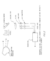
- FIGURE 1 An instrument to measure temperature and emissivity of an object from its spectral radiance is depicted in FIGURE 1.
- An afocal lens recollimates the incoming radiation and directs it to an imaging lens.
- the imaging lens creates an image of the object in the focal plane.
- a detector sensitive to wavelengths from ⁇ L to ⁇ u is placed in the focal plane.
- a wheel with N filters is positioned so that one filter at a time is placed in the optical path.
- Each filter i transmits radiation from ⁇ iL to ⁇ iu to the detector.
- the sub-band ( ⁇ iL , ⁇ iu ) is contained in the pass band ( ⁇ L , ⁇ u ).
- the wheel is moved into several positions, allowing the detector to make measurements in each of the N sub-bands.
- the output of the detector is amplified, digitized and sent to a processor to determine temperature and emissivity.
- An alternate configuration is shown in FIGURE 2 wherein a separate detector is available for each sub-band. Each detector has a filter in front of it allowing only radiation in the desired sub-band to reach the detector.
- a scanner moves the image by the detectors which successively gathers radiation from the image.
- the processor then takes the output of the detectors and determines the temperature and emissivity estimate of the object.
- Remote temperature estimating devices of the type shown in FIGURES 1 and 2 fall into several categories.
- the spectral radiance is measured in one preselected wavelength band and the magnitude of the radiation is related to the object temperature by a table look up processor. More specifically, radiation from the object whose temperature is to be measured enters the lens and is imaged into the detector. Af filter placed in front of the detector restricts the radiation falling on the detector to the preselected band from ⁇ 1 to ⁇ 2 .
- the output R T is given by: where
- the processor contains candidate values of R T computed beforehand for a wide range of temperatures.
- the emissivity is generally assumed to be unity and atmospheric transmission is also assumed to be unity. If these assumptions are correct, the instrument will yield a reasonable answer. However, under many conditions, these assumptions are not valid and the temperature estimate will be inaccurate.
- the measurements from several wavelength bands may be available for temperature estimation.
- the sensor can be a single detector device with a plurality of spectral filters successively placed in front of the detector (FIGURE 2) or a multiple detector device with each detector preceded by a single spectral filter (FIGURE 3).
- the instrument can also be a Fourier spectrometer.
- the resulting measurements are then curve fit to the black body spectral distribution as given by Planck's law (Equations (1) and (2).
- the temperature which provides the best fitting curve to the data is taken as the temperature of the object. This procedure neglects to make use of the fact that some spectral bands are more useful than others in estimating temperature.
- a method of measuring the temperature of a remote body in which the radiances from the body in at least two frequency bands are sensed by a sensor, and the outputs from the sensor are processed according to Planck's law of radiation to provide a value for the temperature of the body, CHARACTERISED IN THAT the number and frequency ranges of the frequency bands and other parameters of the sensor are selected to minimize the bounds on the estimation accuracy by formulating and inverting Fisher's Matrix for the bounds on the estimation accuracy, so as to reduce errors due to noise in the derived temperature value of the body.
- the present invention sets forth a method to select the number and wavelength region of each sub-band.
- a processor is then disclosed which takes the detector outputs and determines temperature and emissivity.
- the processor utilizes a priori data about the object as well as measured data. It may be known beforehand that the temperature and emissivity of the object is confined to certain limits. Such additional information is used to improve the accuracy of the temperature and emissivity measurement.
- the present invention also provides a rationale for selecting the proper spectral bands for the device in FIGURES 1 and 2 and a method for estimating both the temperature of the remote object and of the emissivity thereof.
- the invention provides both temperature and emissivity estimates which approach the fundamental limits of accuracy dictated by statistical theory.
- N (R1, R 2 ,...,R N )
- R (R1, R 2 ,...,R N )
- P R / A ( R / A )
- J- 1 be the inverse of matrix J and let J -1 ij be the (i,j) term of the inverse matrix.
- J ii The bound on the mean squared error in estimating A i is given by J ii .
- ⁇ 2 Ai is the variance of any estimator of A i .
- J -1 11 and J -1 22 which are the bounds on the emissivity and temperature estimates and are given by:
- the bounds J- 1 11 and J -1 22 are a function of the sensor design parameters (G, ⁇ , ⁇ o , F 2 # ), the environment ⁇ A ( ⁇ ) and the unknowns (so ,T).
- the sensor parameters are selected to minimize J -1 11 and J -1 22 for a given environment and a given range of temperatures and emissivities.
- the next step is to specify the processor.
- the estimate is varied until the value of A is found which maximizes ,
- the value of A which maximizes is taken to be the maximum likelihood estimate of A . It will be recognized by those skilled in numerical analysis that techniques exist to rapidly find through the use of a digital processor the value of A which maximizes
- A may not be completely arbitrary and may be a random variable with probability density P A (A).
- P A probability density
- FIGURE 3A depicts the method of choosing sensor or detector parameters.
- FIGURE 3B is a flow diagram of the algorithm which takes sensor data and estimates (s,T).
- FIGURE 3C illustrates the numerical technique to implement the algorithm of FIGURE 3B.
- the irradiance is detected by the sensor and the output R i of the detector for the ith sub-band of the sensor is
- the estimate of the ith component of A must have a mean squared error ⁇ 2 i which is no less than J -1 ii .
- the bounds on emissivity and temperature are J 11 and J 22 , respectively, and are and
- the bounds J -1 11 and J -1 22 are functions of the atmospheric transmission ⁇ A , the object temperature and emissivity and the sensor parameters.
- the design parameters are chosen to minimize J -1 11 and J -1 22 for a given object temperature and emissivity and for a given atmospheric transmission.
- the mathematical procedures to find the sensor design parameters are referred to as optimization procedures. It should be noted that the sensor parameters which minimize J -1 11 may not be the same set that minimized J -1 22 . In other words, the sensor which best estimates temperature may not be the best one to estimate emissivity. Also, the sensor which is optimum for one atmospheric transmission ⁇ A may not be otpimum for another value of ⁇ A .
- J -1 11 and J 22 The most straightforward way to minimize J -1 11 and J 22 is to exhaustively evaluate J -1 11 is and J -1 22 at all values of the sensor parameters. This procedure is time consuming, but feasible with present day fast computers. Another approach is the steepest gradient method. In this method, the gradients of J -1 11 and J -1 22 are formed as and where a G , a ⁇ o , ... a F# are unit vectors. J -1 11 is optimized by starting at one candidate design point P o where
- J -1 11 at P o namely J -1 11 (P o )
- P o The next estimate of P , namely P 1 becomes where (AG, ⁇ ⁇ o ,..., #F ) is a suitably small increment in P. This procedure is repeated until the value which minimizes J-1 11 is found. Asimilar procedure is used to minimize J-1 22. The skilled mathematician will find many more ways to minimize J-1 11 and J-1 22.
- the processor illustrated in FIGURES 1 and 2 effectively finds the value of (s o ,T) which minimizes L( R , ⁇ A ).
- the outputs R from the detectors are substituted into L (R, ⁇ A ) and ⁇ A is varied until L (R, ⁇ A ) is maximized.
- the value of ⁇ A which maximizes L (R, ⁇ A ) is taken to be the estimate of A.
- One means to find ⁇ A is to exhaustively evaluate L( R , ⁇ A ) over the entire range of values that A can have. For example, if it is known that and values of can be used as candidates where and i ranges from 0 to M and j ranges from 0 to N.
- radiators which properties are specified by the temperature and emissivity
- other radiators do exist.
- the exhaust plume of a gas turbine engine is an emitter which has its unique characteristics.
- emitters are also included as a part of this invention. If a mathematical expression can be written for the spectral radiance of the radiator, methods and instruments completely analagous to those described above can be used to measure and estimate the parameters of that expression.
Landscapes
- Physics & Mathematics (AREA)
- General Physics & Mathematics (AREA)
- Spectroscopy & Molecular Physics (AREA)
- Radiation Pyrometers (AREA)
Claims (5)
Applications Claiming Priority (2)
| Application Number | Priority Date | Filing Date | Title |
|---|---|---|---|
| US521967 | 1990-05-11 | ||
| US07/521,967 US5099121A (en) | 1990-05-11 | 1990-05-11 | Temperature measuring method using infrared sensors and processor |
Publications (3)
| Publication Number | Publication Date |
|---|---|
| EP0456412A2 EP0456412A2 (fr) | 1991-11-13 |
| EP0456412A3 EP0456412A3 (en) | 1992-09-09 |
| EP0456412B1 true EP0456412B1 (fr) | 1995-06-28 |
Family
ID=24078868
Family Applications (1)
| Application Number | Title | Priority Date | Filing Date |
|---|---|---|---|
| EP91303974A Expired - Lifetime EP0456412B1 (fr) | 1990-05-11 | 1991-05-02 | Procédé pour mesurer la température utilisant des détecteurs infrarouges et processeur |
Country Status (3)
| Country | Link |
|---|---|
| US (1) | US5099121A (fr) |
| EP (1) | EP0456412B1 (fr) |
| DE (1) | DE69110759T2 (fr) |
Cited By (1)
| Publication number | Priority date | Publication date | Assignee | Title |
|---|---|---|---|---|
| WO2018140124A3 (fr) * | 2016-11-21 | 2018-10-04 | Bae Systems Information And Electronic Systems Integration Inc. | Détermination automatisée de configuration de fusée |
Families Citing this family (22)
| Publication number | Priority date | Publication date | Assignee | Title |
|---|---|---|---|---|
| WO1993018494A1 (fr) * | 1992-03-11 | 1993-09-16 | The Boeing Company | Systeme de surveillance thermique concernant le fonctionnement d'equipements |
| US5272340A (en) * | 1992-09-29 | 1993-12-21 | Amara, Inc. | Infrared imaging system for simultaneous generation of temperature, emissivity and fluorescence images |
| US5868496A (en) * | 1994-06-28 | 1999-02-09 | Massachusetts Institute Of Technology | Non-contact surface temperature, emissivity, and area estimation |
| US6222111B1 (en) * | 1995-06-07 | 2001-04-24 | Raytheon Company | Spectrally selective thermopile detector |
| DE19528960C2 (de) * | 1995-08-08 | 1997-07-17 | Eltro Gmbh | Verfahren und Einrichtung zur Fernmessung von Luftschadstoffen |
| US5815410A (en) * | 1996-05-03 | 1998-09-29 | Raytek Subsidiary, Inc. | Ratio type infrared thermometer |
| DE19721475A1 (de) * | 1997-05-23 | 1998-11-26 | Eko Stahl Gmbh | Verfahren zur berührungslosen Temperaturmessung |
| RU2151382C1 (ru) * | 1998-07-17 | 2000-06-20 | Свет Дарий Яковлевич | Способ пирометрических измерений |
| GB2365120B (en) * | 2000-07-21 | 2004-11-17 | Infrared Integrated Syst Ltd | Multipurpose detector |
| RU2225600C2 (ru) * | 2001-02-14 | 2004-03-10 | Закрытое акционерное общество "СТИНС-ТАГАНРОГ" | Пирометр |
| US6999163B2 (en) * | 2003-07-28 | 2006-02-14 | Harris Corporation | Embedded moems sensor for fluid dielectrics in RF applications |
| US20050276308A1 (en) * | 2004-06-10 | 2005-12-15 | Pint Charles S | Method and apparatus for measuring temperature and emissivity |
| US6970110B1 (en) | 2005-01-08 | 2005-11-29 | Collins Dennis G | Probability centrifuge algorithm with minimum laterally adiabatically-reduced Fisher information calculation |
| US20090285259A1 (en) * | 2008-05-14 | 2009-11-19 | General Electric Company | System and method for thermal inspection of objects |
| US20100182153A1 (en) * | 2008-11-25 | 2010-07-22 | Kurt Holdgaard Jensen | Apparatus with an infrared sensor and magnetic near field communication properties for monitoring activity in a selected area |
| US8282273B2 (en) * | 2009-03-24 | 2012-10-09 | K-Space Associates, Inc. | Blackbody fitting for temperature determination |
| US8410946B2 (en) | 2010-03-05 | 2013-04-02 | General Electric Company | Thermal measurement system and method for leak detection |
| US8702372B2 (en) | 2010-05-03 | 2014-04-22 | Bha Altair, Llc | System and method for adjusting compressor inlet fluid temperature |
| US9097182B2 (en) | 2010-08-05 | 2015-08-04 | General Electric Company | Thermal control system for fault detection and mitigation within a power generation system |
| US9019108B2 (en) | 2010-08-05 | 2015-04-28 | General Electric Company | Thermal measurement system for fault detection within a power generation system |
| US8627643B2 (en) * | 2010-08-05 | 2014-01-14 | General Electric Company | System and method for measuring temperature within a turbine system |
| US9970821B2 (en) * | 2015-04-16 | 2018-05-15 | Raytheon Company | Characterization of spectral emissivity via thermal conductive heating and in-situ radiance measurement using a low-e mirror |
Family Cites Families (7)
| Publication number | Priority date | Publication date | Assignee | Title |
|---|---|---|---|---|
| DE3115887C2 (de) * | 1981-04-21 | 1986-07-03 | Deutsche Forschungs- und Versuchsanstalt für Luft- und Raumfahrt e.V., 5000 Köln | Verfahren und Vorrichtung zur berührungslosen Infrarot-Strahlungsmessung der Temperatur eines Strahlers |
| DE3149523A1 (de) * | 1981-12-14 | 1983-06-16 | VEB Meßgerätewerk "Erich Weinert" Magdeburg Betrieb des Kombinates VEB EAW Berlin-Treptow "Friedrich Ebert", 3011 Magdeburg | Verfahren und einrichtung zur beruehrungslosen temperaturmessung |
| EP0129150B1 (fr) * | 1983-06-16 | 1989-04-26 | Deutsche Forschungsanstalt für Luft- und Raumfahrt e.V. | Procédé pour mesurer sans contact et indépendemment du pouvoir émissif la température d'un objet par mesure du rayonnement, et dispositif pour la mise en oeuvre du procédé |
| US4561786A (en) * | 1984-03-15 | 1985-12-31 | Williamson Corporation | Temperature measuring apparatus |
| GB8415164D0 (en) * | 1984-06-14 | 1984-07-18 | Beta Instr Co | Measuring temperature of object |
| US4750139A (en) * | 1985-01-24 | 1988-06-07 | Accufiber, Inc. | Blackbody radiation sensing optical fiber thermometer system |
| US4845647A (en) * | 1985-01-24 | 1989-07-04 | Accufiber, Inc. | Method and apparatus for determining temperature in a blackbody radiation sensing system |
-
1990
- 1990-05-11 US US07/521,967 patent/US5099121A/en not_active Expired - Lifetime
-
1991
- 1991-05-02 EP EP91303974A patent/EP0456412B1/fr not_active Expired - Lifetime
- 1991-05-02 DE DE69110759T patent/DE69110759T2/de not_active Expired - Lifetime
Cited By (2)
| Publication number | Priority date | Publication date | Assignee | Title |
|---|---|---|---|---|
| WO2018140124A3 (fr) * | 2016-11-21 | 2018-10-04 | Bae Systems Information And Electronic Systems Integration Inc. | Détermination automatisée de configuration de fusée |
| US10371494B2 (en) | 2016-11-21 | 2019-08-06 | Bae Systems Information And Electronic Systems Integration Inc. | Automated determination of rocket configuration |
Also Published As
| Publication number | Publication date |
|---|---|
| DE69110759T2 (de) | 1995-11-16 |
| US5099121A (en) | 1992-03-24 |
| EP0456412A3 (en) | 1992-09-09 |
| DE69110759D1 (de) | 1995-08-03 |
| EP0456412A2 (fr) | 1991-11-13 |
Similar Documents
| Publication | Publication Date | Title |
|---|---|---|
| EP0456412B1 (fr) | Procédé pour mesurer la température utilisant des détecteurs infrarouges et processeur | |
| EP1303742B1 (fr) | Derive spectrale et technique de correction pour systemes d'imagerie hyperspectraux | |
| US5445453A (en) | Method for airborne surveying which includes the determination of the apparent thermal inertia of the material being surveyed | |
| Cooper et al. | Evaluating atmospheric correction models for retrieving surface temperatures from the AVHRR over a tallgrass prairie | |
| US8050884B2 (en) | Method and apparatus for determining the emissivity, area and temperature of an object | |
| CN111044153A (zh) | 一种图谱关联系统红外光谱的非线性定标方法及装置 | |
| Kerekes et al. | An analytical model of earth-observational remote sensing systems | |
| CN113567000A (zh) | 一种基于神经网络的多光谱温度测量方法 | |
| Gonzalez-Chavez et al. | Radiometric calibration of digital counts of infrared thermal cameras | |
| Khatri et al. | Retrieval of cloud properties from spectral zenith radiances observed by sky radiometers | |
| Wang et al. | Evaluation of the spectral misalignment on the Earth Clouds, Aerosols and Radiation Explorer/multi-spectral imager cloud product | |
| Bhatia et al. | Sensitivity of reflectance to water vapor and aerosol optical thickness | |
| Thompson et al. | Calibration and performance of the high resolution volatiles and minerals Moon Mapper (HVM3) on Lunar Trailblazer | |
| Xu et al. | In-flight spectral response function retrieval of a multispectral radiometer based on the functional data analysis technique | |
| Kerekes et al. | Parameter trade-offs for imaging spectroscopy systems. | |
| Eismann et al. | Focal plane array nonlinearity and nonuniformity impacts to target detection with thermal infrared imaging spectrometers | |
| CN113175994B (zh) | 星载傅里叶变换红外光谱仪光谱噪声分析方法、系统及介质 | |
| Wigton | Use of Landsat technology by Statistical Reporting service | |
| Pagano et al. | Early calibration results from the atmospheric infrared sounder (AIRS) on Aqua | |
| CN114383729B (zh) | 一种外场光谱仪采集数据质量的评估方法及装置 | |
| Akın | Evaluation of Range Estimation Performance of FLIR with Field Requirements Criteria | |
| Goldberg et al. | Using MODIS with AIRS to develop an operational cloud-cleared radiance product | |
| Coll et al. | A comparison of methods for surface temperature and emissivity estimation | |
| Akhoondzadeh et al. | Improved ISAC algorithm to retrieve atmospheric parameters from HyTES hyperspectral Images using Gaussian mixture model and error ellipse | |
| Paden et al. | Comparisons between Point Response Function measurements and theory for the Clouds and the Earth's Radiant Energy System (CERES) TRMM and the EOS-AM spacecraft thermistor bolometer sensors |
Legal Events
| Date | Code | Title | Description |
|---|---|---|---|
| PUAI | Public reference made under article 153(3) epc to a published international application that has entered the european phase |
Free format text: ORIGINAL CODE: 0009012 |
|
| AK | Designated contracting states |
Kind code of ref document: A2 Designated state(s): DE FR GB IT NL |
|
| PUAL | Search report despatched |
Free format text: ORIGINAL CODE: 0009013 |
|
| AK | Designated contracting states |
Kind code of ref document: A3 Designated state(s): DE FR GB IT NL |
|
| 17P | Request for examination filed |
Effective date: 19921102 |
|
| 17Q | First examination report despatched |
Effective date: 19931119 |
|
| GRAA | (expected) grant |
Free format text: ORIGINAL CODE: 0009210 |
|
| AK | Designated contracting states |
Kind code of ref document: B1 Designated state(s): DE FR GB IT NL |
|
| PG25 | Lapsed in a contracting state [announced via postgrant information from national office to epo] |
Ref country code: NL Free format text: LAPSE BECAUSE OF FAILURE TO SUBMIT A TRANSLATION OF THE DESCRIPTION OR TO PAY THE FEE WITHIN THE PRESCRIBED TIME-LIMIT Effective date: 19950628 |
|
| ITF | It: translation for a ep patent filed | ||
| REF | Corresponds to: |
Ref document number: 69110759 Country of ref document: DE Date of ref document: 19950803 |
|
| ET | Fr: translation filed | ||
| NLV1 | Nl: lapsed or annulled due to failure to fulfill the requirements of art. 29p and 29m of the patents act | ||
| PLBE | No opposition filed within time limit |
Free format text: ORIGINAL CODE: 0009261 |
|
| STAA | Information on the status of an ep patent application or granted ep patent |
Free format text: STATUS: NO OPPOSITION FILED WITHIN TIME LIMIT |
|
| 26N | No opposition filed | ||
| REG | Reference to a national code |
Ref country code: GB Ref legal event code: 732E |
|
| REG | Reference to a national code |
Ref country code: FR Ref legal event code: TP |
|
| REG | Reference to a national code |
Ref country code: GB Ref legal event code: 732E |
|
| REG | Reference to a national code |
Ref country code: FR Ref legal event code: TP |
|
| REG | Reference to a national code |
Ref country code: GB Ref legal event code: IF02 |
|
| PGFP | Annual fee paid to national office [announced via postgrant information from national office to epo] |
Ref country code: GB Payment date: 20100329 Year of fee payment: 20 |
|
| PGFP | Annual fee paid to national office [announced via postgrant information from national office to epo] |
Ref country code: FR Payment date: 20100525 Year of fee payment: 20 |
|
| PGFP | Annual fee paid to national office [announced via postgrant information from national office to epo] |
Ref country code: IT Payment date: 20100513 Year of fee payment: 20 Ref country code: DE Payment date: 20100430 Year of fee payment: 20 |
|
| REG | Reference to a national code |
Ref country code: DE Ref legal event code: R071 Ref document number: 69110759 Country of ref document: DE |
|
| REG | Reference to a national code |
Ref country code: GB Ref legal event code: PE20 Expiry date: 20110501 |
|
| PG25 | Lapsed in a contracting state [announced via postgrant information from national office to epo] |
Ref country code: GB Free format text: LAPSE BECAUSE OF EXPIRATION OF PROTECTION Effective date: 20110501 |
|
| PG25 | Lapsed in a contracting state [announced via postgrant information from national office to epo] |
Ref country code: DE Free format text: LAPSE BECAUSE OF EXPIRATION OF PROTECTION Effective date: 20110502 |