EP0456423A2 - Paquet de plaques à circuits imprimés à refroidissement à buse entre les plaques - Google Patents
Paquet de plaques à circuits imprimés à refroidissement à buse entre les plaques Download PDFInfo
- Publication number
- EP0456423A2 EP0456423A2 EP91304013A EP91304013A EP0456423A2 EP 0456423 A2 EP0456423 A2 EP 0456423A2 EP 91304013 A EP91304013 A EP 91304013A EP 91304013 A EP91304013 A EP 91304013A EP 0456423 A2 EP0456423 A2 EP 0456423A2
- Authority
- EP
- European Patent Office
- Prior art keywords
- circuit pack
- board
- circuit
- pack according
- fluid
- Prior art date
- Legal status (The legal status is an assumption and is not a legal conclusion. Google has not performed a legal analysis and makes no representation as to the accuracy of the status listed.)
- Withdrawn
Links
Images


Classifications
-
- H—ELECTRICITY
- H05—ELECTRIC TECHNIQUES NOT OTHERWISE PROVIDED FOR
- H05K—PRINTED CIRCUITS; CASINGS OR CONSTRUCTIONAL DETAILS OF ELECTRIC APPARATUS; MANUFACTURE OF ASSEMBLAGES OF ELECTRICAL COMPONENTS
- H05K7/00—Constructional details common to different types of electric apparatus
- H05K7/20—Modifications to facilitate cooling, ventilating, or heating
-
- H—ELECTRICITY
- H05—ELECTRIC TECHNIQUES NOT OTHERWISE PROVIDED FOR
- H05K—PRINTED CIRCUITS; CASINGS OR CONSTRUCTIONAL DETAILS OF ELECTRIC APPARATUS; MANUFACTURE OF ASSEMBLAGES OF ELECTRICAL COMPONENTS
- H05K7/00—Constructional details common to different types of electric apparatus
- H05K7/20—Modifications to facilitate cooling, ventilating, or heating
- H05K7/2029—Modifications to facilitate cooling, ventilating, or heating using a liquid coolant with phase change in electronic enclosures
- H05K7/20345—Sprayers; Atomizers
-
- H—ELECTRICITY
- H05—ELECTRIC TECHNIQUES NOT OTHERWISE PROVIDED FOR
- H05K—PRINTED CIRCUITS; CASINGS OR CONSTRUCTIONAL DETAILS OF ELECTRIC APPARATUS; MANUFACTURE OF ASSEMBLAGES OF ELECTRICAL COMPONENTS
- H05K1/00—Printed circuits
- H05K1/02—Details
- H05K1/0272—Adaptations for fluid transport, e.g. channels, holes
-
- H—ELECTRICITY
- H05—ELECTRIC TECHNIQUES NOT OTHERWISE PROVIDED FOR
- H05K—PRINTED CIRCUITS; CASINGS OR CONSTRUCTIONAL DETAILS OF ELECTRIC APPARATUS; MANUFACTURE OF ASSEMBLAGES OF ELECTRICAL COMPONENTS
- H05K2201/00—Indexing scheme relating to printed circuits covered by H05K1/00
- H05K2201/06—Thermal details
- H05K2201/064—Fluid cooling, e.g. by integral pipes
-
- H—ELECTRICITY
- H05—ELECTRIC TECHNIQUES NOT OTHERWISE PROVIDED FOR
- H05K—PRINTED CIRCUITS; CASINGS OR CONSTRUCTIONAL DETAILS OF ELECTRIC APPARATUS; MANUFACTURE OF ASSEMBLAGES OF ELECTRICAL COMPONENTS
- H05K2201/00—Indexing scheme relating to printed circuits covered by H05K1/00
- H05K2201/09—Shape and layout
- H05K2201/09009—Substrate related
- H05K2201/09063—Holes or slots in insulating substrate not used for electrical connections
-
- Y—GENERAL TAGGING OF NEW TECHNOLOGICAL DEVELOPMENTS; GENERAL TAGGING OF CROSS-SECTIONAL TECHNOLOGIES SPANNING OVER SEVERAL SECTIONS OF THE IPC; TECHNICAL SUBJECTS COVERED BY FORMER USPC CROSS-REFERENCE ART COLLECTIONS [XRACs] AND DIGESTS
- Y10—TECHNICAL SUBJECTS COVERED BY FORMER USPC
- Y10S—TECHNICAL SUBJECTS COVERED BY FORMER USPC CROSS-REFERENCE ART COLLECTIONS [XRACs] AND DIGESTS
- Y10S165/00—Heat exchange
- Y10S165/908—Fluid jets
-
- Y—GENERAL TAGGING OF NEW TECHNOLOGICAL DEVELOPMENTS; GENERAL TAGGING OF CROSS-SECTIONAL TECHNOLOGIES SPANNING OVER SEVERAL SECTIONS OF THE IPC; TECHNICAL SUBJECTS COVERED BY FORMER USPC CROSS-REFERENCE ART COLLECTIONS [XRACs] AND DIGESTS
- Y10—TECHNICAL SUBJECTS COVERED BY FORMER USPC
- Y10S—TECHNICAL SUBJECTS COVERED BY FORMER USPC CROSS-REFERENCE ART COLLECTIONS [XRACs] AND DIGESTS
- Y10S428/00—Stock material or miscellaneous articles
- Y10S428/901—Printed circuit
Definitions
- An object of this invention is to provide a cooling system for electronic circuit packs that is simple, relatively inexpensive, and uses almost no space on the circuit board.
- a fluid-cooled circuit pack comprising a circuit board having front and back major surfaces with at least one heat generating component mounted on the front surface.
- the circuit pack also includes conduit means connectable to a source of compressed fluid and attached to the back surface of the circuit board to form a sealed plenum for conducting cooling fluid in a direction essentially parallel to said surfaces to a predetermined area of the back surface of the board.
- At least one hole extends from the back surface to the front surface in the vicinity of said component to form a cooling jet when the conduit means is connected to the source.
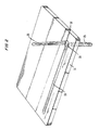
- a circuit pack 10 may have all of its components and wiring mounted on its front side 12.
- the many components may be, for example, an integrated circuit 14 and a capacitor 16 that require cooling.
- a projection 17 on one edge of the circuit pack may contain gold or silver plated "fingers" for plugging into a matching socket in a welt-known manner to provide the electrical circuit connections to and from the circuit pack.
- the desired cooling may be accomplished according to the invention with the aid of one or more small holes 18 that exit the circuit board beneath the targeted component.
- Pressurized cooling fluid which in the simplest case can be compressed air, is supplied through holes 18 via a pump 20, hose 22, connector 24, tube 25, and tunnels 26 and 28 carved in the surface opposite to the front surface 12 including the components.
- Holes 18 are orifices judiciously placed to form fluid jets impinging upon the desired areas of the respective components.
- the orifices may be of vinous shapes such as, for example, round, rectangutar or triangular, to optimize ease of manufacture or the physical characteristics of the created fluid jets.
- the orifices may be perpendicular to, or alternatively at an oblique angle to, the surface 12 of the board. In this manner components may be cooled by a broad, almost uniform flow of fluid or the flow may be concentrated on a particular hot spot.
- the jets may be aimed to enhance convection without actually impinging directly upon any component.
- the back side of the board is typically smooth.
- the solid board 31 which is typically glass epoxy or metal, may have machined or molded in the top side thereof a pair of tunnels 33 and 35 which mate with the tunnels 26 and 28 to form plenums and which intersect in an area 37.
- a tubular fitting 39 may be attached to area 37 and extend through the back side of board 31.
- Board 31 is, therefore, attached to the back side of board 12 to form the circuit pack 10 of FIG. 1.
- the attachment process should provide an airtight seat to avoid wasting pressurized fluid and creating uncontrolled fluid flow.
- Epoxy gtue and hot plastic bonding are examples of processes that may be used.
- the plenums formed by tunnels 26 and 28 and grooves 33 and 35 supply the compressed fluid to orifices 18.
- Very substantial component cooling can be effected with a source of compressed air in the range 1.38 to 4. 14 x 105 pa, and circular orifices in the order of 0.025 to 0.254 cm in diameter.
- adiabatic expansion of the fluid between the orifice and the component reduces the fluid temperature to provide additional cooling. Since the cooling jets may be very small, depending upon the number of cooling jets to be supplied, the inboard plenum can be surprisingly narrow and still supply a sufficient quantity of fluid.
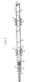
- a first printed wiring board 42 may have mounted thereon via thru-hole technology, for example, components 44 and 45 that require cooling.
- a single orifice 46 may be located under component 44 and two orifices 48 and 49, respectively, may be located under component 45.
- a printed circuit board 52 may have components 54 and 55 mounted thereon.
- Component 54 may require a large amount of cooling at a particular hot spot 56.
- board 52 may have a perpendicular hole 57 and oblique holes 58 and 59 therethrough.
- Component 55 for example, may normally develop a hot spot on its end.
- An oblique hole 61 through board 52 may be located to provide the appropriately directed fluid jet.
- Boards 42 and 52 are joined into a single circuit pack by a spacer 63 to form a plenum chamber 64 of virtually the entire space between the two boards.
- a pipe-threaded fitting 65 attached to spacer 63 connects the plenum chamber to a source of pressurized fluid.
- electrical connector projections 67 and 68 may be offset with respect to the fitting 65 (i.e., at different depths behind the viewed cross-section plane).
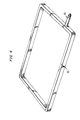
- FIG. 4 is a three-dimensional view of spacer 63.
- Fluid connector 65 may conveniently be part of a well-known quick connect compressed air fitting.
- spacer 63 should be attached to the back sides of boards 42 and 52 in an airtight manner. Since the periphery of each board is normally component-free, there should be no projections of wire or solder to impede the process.
- FIG. 5 An embodiment of a circuit pack according to the invention that conveniently can be inserted and removed from an equipment shelf containing many circuit packs will be described with reference to FIG. 5.
- the equipment shelf is shown in cross-section, cut by a plane a short distance in front of the circuit pack.
- a circuit pack 70 having inboard cooling jets 72 according to the invention rests on shelf rails 73 and 74.
- a pair of projections 76 on each rail 73 and 74 form a channel to guide the circuit pack into and out of the equipment.
- a pair of rails 78 and 79 with projections 80 may guide the top of circuit pack 70 and hold it in a vertical position.
- a backplane socket 82 receives the "gold fingers" of the circuit pack in a conventional manner to make the electrical connection between the circuit pack and the equipment backplane wiring.
- a conical nozzle 84 at the edge of the circuit pack 70 forms an inlet to the internal plenum 85 of the circuit pack.
- the equipment backplane may also include an external plenum chamber 86, shown in cross-section in a plane through the center of nozzle 84.
- Plenum chamber 86 may have one or more cylindrical output ports 87.
- An O ring 88 forms a compression seal between nozzle 84 and port 87.
- a valve 90 in the center of each port, normally held closed to avoid fluid leakage by a spring 92, is forced open by the force of nozzle 84 on funnel-shaped member 89. The opening of valve 90 thereby permits the escape of cooling fluid through the perforations 91 of the funnel member into the nozzle 84 and plenum 85.
- a locking lever 99 pivotally connected to circuit pack 70, can bear against rail 79 to force circuit pack 70 in place and hold it there against the resistance of socket 82, valve 90, O ring 88 and the pressurized cooling fluid.
- circuit packs 70 with inboard jet cooling according to the invention can be inserted and removed conveniently without undue disturbance.
Landscapes
- Engineering & Computer Science (AREA)
- Microelectronics & Electronic Packaging (AREA)
- Physics & Mathematics (AREA)
- Thermal Sciences (AREA)
- Cooling Or The Like Of Electrical Apparatus (AREA)
- Cooling Or The Like Of Semiconductors Or Solid State Devices (AREA)
Applications Claiming Priority (2)
| Application Number | Priority Date | Filing Date | Title |
|---|---|---|---|
| US522290 | 1990-05-11 | ||
| US07/522,290 US5067047A (en) | 1990-05-11 | 1990-05-11 | Circuit pack with inboard jet cooling |
Publications (2)
| Publication Number | Publication Date |
|---|---|
| EP0456423A2 true EP0456423A2 (fr) | 1991-11-13 |
| EP0456423A3 EP0456423A3 (en) | 1992-08-26 |
Family
ID=24080281
Family Applications (1)
| Application Number | Title | Priority Date | Filing Date |
|---|---|---|---|
| EP19910304013 Withdrawn EP0456423A3 (en) | 1990-05-11 | 1991-05-03 | Circuit pack with inboard jet cooling |
Country Status (6)
| Country | Link |
|---|---|
| US (1) | US5067047A (fr) |
| EP (1) | EP0456423A3 (fr) |
| JP (1) | JPH04229641A (fr) |
| KR (1) | KR910021194A (fr) |
| AU (1) | AU7530091A (fr) |
| CA (1) | CA2039058A1 (fr) |
Cited By (3)
| Publication number | Priority date | Publication date | Assignee | Title |
|---|---|---|---|---|
| EP0893041A4 (fr) * | 1996-04-10 | 1999-11-17 | Motorola Inc | Appareil et procede de refroidissement d'un module electronique par ruissellement |
| EP0908080A4 (fr) * | 1996-06-28 | 2000-03-22 | Motorola Inc | Appareil a cartes a circuits avec refroidissement par pulverisation |
| WO2017127109A1 (fr) * | 2016-01-22 | 2017-07-27 | Hewlett Packard Enterprise Development Lp | Routage d'un élément de refroidissement le long d'une carte |
Families Citing this family (35)
| Publication number | Priority date | Publication date | Assignee | Title |
|---|---|---|---|---|
| US5220956A (en) * | 1992-01-24 | 1993-06-22 | Texas Instruments Incorporated | Multiple device fixture used in conjunction with a standard temperature forcing unit |
| US5424914A (en) * | 1993-11-24 | 1995-06-13 | Unisys Corporation | Through backplane impingement cooling apparatus |
| US5473508A (en) * | 1994-05-31 | 1995-12-05 | At&T Global Information Solutions Company | Focused CPU air cooling system including high efficiency heat exchanger |
| US5566377A (en) * | 1995-07-10 | 1996-10-15 | Lee; Richard | Heat dissipating apparatus |
| US5823005A (en) * | 1997-01-03 | 1998-10-20 | Ncr Corporation | Focused air cooling employing a dedicated chiller |
| US5907473A (en) * | 1997-04-04 | 1999-05-25 | Raytheon Company | Environmentally isolated enclosure for electronic components |
| SE514171C2 (sv) * | 1998-02-03 | 2001-01-15 | Ericsson Telefon Ab L M | Anordning och förfarande för luftkylning av en elektrisk anordning |
| US6799628B1 (en) * | 2000-07-20 | 2004-10-05 | Honeywell International Inc. | Heat exchanger having silicon nitride substrate for mounting high power electronic components |
| US6427466B1 (en) | 2000-12-12 | 2002-08-06 | Celletra Ltd | Forced convection cooling system for electronic equipment |
| US6679315B2 (en) | 2002-01-14 | 2004-01-20 | Marconi Communications, Inc. | Small scale chip cooler assembly |
| US6603662B1 (en) * | 2002-01-25 | 2003-08-05 | Sun Microsystems, Inc. | Computer cooling system |
| US6765796B2 (en) | 2002-11-21 | 2004-07-20 | Teradyne, Inc. | Circuit board cover with exhaust apertures for cooling electronic components |
| NL1034420C2 (nl) | 2007-09-24 | 2009-03-26 | Thales Nederland Bv | Rechtstreeks geïnjecteerde gedwongen convectiekoeling voor elektronica. |
| WO2010011224A1 (fr) * | 2008-07-24 | 2010-01-28 | Hewlett-Packard Development Company, L.P. | Refroidissement localisé pour un dispositif électronique |
| US7944694B2 (en) * | 2008-10-23 | 2011-05-17 | International Business Machines Corporation | Liquid cooling apparatus and method for cooling blades of an electronic system chassis |
| US7916483B2 (en) * | 2008-10-23 | 2011-03-29 | International Business Machines Corporation | Open flow cold plate for liquid cooled electronic packages |
| US7961475B2 (en) | 2008-10-23 | 2011-06-14 | International Business Machines Corporation | Apparatus and method for facilitating immersion-cooling of an electronic subsystem |
| US7885070B2 (en) * | 2008-10-23 | 2011-02-08 | International Business Machines Corporation | Apparatus and method for immersion-cooling of an electronic system utilizing coolant jet impingement and coolant wash flow |
| US7983040B2 (en) * | 2008-10-23 | 2011-07-19 | International Business Machines Corporation | Apparatus and method for facilitating pumped immersion-cooling of an electronic subsystem |
| US8345423B2 (en) | 2010-06-29 | 2013-01-01 | International Business Machines Corporation | Interleaved, immersion-cooling apparatuses and methods for cooling electronic subsystems |
| US8184436B2 (en) | 2010-06-29 | 2012-05-22 | International Business Machines Corporation | Liquid-cooled electronics rack with immersion-cooled electronic subsystems |
| US8351206B2 (en) | 2010-06-29 | 2013-01-08 | International Business Machines Corporation | Liquid-cooled electronics rack with immersion-cooled electronic subsystems and vertically-mounted, vapor-condensing unit |
| US8369091B2 (en) | 2010-06-29 | 2013-02-05 | International Business Machines Corporation | Interleaved, immersion-cooling apparatus and method for an electronic subsystem of an electronics rack |
| US8179677B2 (en) | 2010-06-29 | 2012-05-15 | International Business Machines Corporation | Immersion-cooling apparatus and method for an electronic subsystem of an electronics rack |
| US8711564B2 (en) * | 2011-01-31 | 2014-04-29 | Qualitics, Inc | Method and system for cooling of integrated circuits |
| US9484283B2 (en) | 2013-01-04 | 2016-11-01 | Toyota Motor Engineering & Manufacturing North America Inc. | Modular jet impingement cooling apparatuses with exchangeable jet plates |
| US8643173B1 (en) | 2013-01-04 | 2014-02-04 | Toyota Motor Engineering & Manufacturing North America, Inc. | Cooling apparatuses and power electronics modules with single-phase and two-phase surface enhancement features |
| US9460985B2 (en) | 2013-01-04 | 2016-10-04 | Toyota Motor Engineering & Manufacturing North America, Inc. | Cooling apparatuses having a jet orifice surface with alternating vapor guide channels |
| US8981556B2 (en) | 2013-03-19 | 2015-03-17 | Toyota Motor Engineering & Manufacturing North America, Inc. | Jet impingement cooling apparatuses having non-uniform jet orifice sizes |
| US9247679B2 (en) | 2013-05-24 | 2016-01-26 | Toyota Motor Engineering & Manufacturing North America, Inc. | Jet impingement coolers and power electronics modules comprising the same |
| US9803938B2 (en) | 2013-07-05 | 2017-10-31 | Toyota Motor Engineering & Manufacturing North America, Inc. | Cooling assemblies having porous three dimensional surfaces |
| US9257365B2 (en) | 2013-07-05 | 2016-02-09 | Toyota Motor Engineering & Manufacturing North America, Inc. | Cooling assemblies and power electronics modules having multiple-porosity structures |
| US9131631B2 (en) | 2013-08-08 | 2015-09-08 | Toyota Motor Engineering & Manufacturing North America, Inc. | Jet impingement cooling apparatuses having enhanced heat transfer assemblies |
| US9480149B2 (en) * | 2013-12-10 | 2016-10-25 | Brocade Communications Systems, Inc. | Printed circuit board with fluid flow channels |
| GB202020109D0 (en) * | 2020-12-18 | 2021-02-03 | Iceotope Group Ltd | Dielectric coolant distribution manifold |
Family Cites Families (16)
| Publication number | Priority date | Publication date | Assignee | Title |
|---|---|---|---|---|
| US2445852A (en) * | 1941-04-12 | 1948-07-27 | Glenn L Martin Co | Gun turret |
| GB1105068A (en) * | 1964-10-31 | 1968-03-06 | Hitachi Ltd | Improvements in or relating to printed circuits |
| US3626251A (en) * | 1970-01-19 | 1971-12-07 | Bendix Corp | Air cooling system for cabinet mounted equipment |
| US4166665A (en) * | 1976-12-27 | 1979-09-04 | Cutchaw John M | Liquid cooled connector for large scale integrated circuit packages |
| US4277816A (en) * | 1979-05-29 | 1981-07-07 | International Business Machines Corporation | Electronic circuit module cooling |
| US4399484A (en) * | 1981-03-10 | 1983-08-16 | The United States Of America As Represented By The Secretary Of The Air Force | Integral electric module and assembly jet cooling system |
| US4498118A (en) * | 1983-04-05 | 1985-02-05 | Bicc-Vero Electronics Limited | Circuit board installation |
| EP0204568A3 (fr) * | 1985-06-05 | 1988-07-27 | Harry Arthur Hele Spence-Bate | Composants de circuits à basse puissance |
| US4614389A (en) * | 1985-06-17 | 1986-09-30 | At&T Bell Laboratories | Circuit board assembly for accurate insertion |
| US4774630A (en) * | 1985-09-30 | 1988-09-27 | Microelectronics Center Of North Carolina | Apparatus for mounting a semiconductor chip and making electrical connections thereto |
| DE3680774D1 (de) * | 1985-12-16 | 1991-09-12 | Hitachi Ltd | Integriertes halbleiterbauelement. |
| US4739443A (en) * | 1985-12-30 | 1988-04-19 | Olin Corporation | Thermally conductive module |
| US4674004A (en) * | 1986-07-03 | 1987-06-16 | Burroughs Corporation | Parallel-flow air system for cooling electronic equipment |
| US4851965A (en) * | 1987-03-09 | 1989-07-25 | Unisys Corporation | Directed air management system for cooling multiple heat sinks |
| US4839774A (en) * | 1988-01-25 | 1989-06-13 | Digital Equipment Corporation | Apparatus and method for cooling electronic component packages using an array of directed nozzles fabricated in the circuit board |
| US4962444A (en) * | 1989-01-03 | 1990-10-09 | Sunstrand Corporation | Cold chassis for cooling electronic circuit components on an electronic board |
-
1990
- 1990-05-11 US US07/522,290 patent/US5067047A/en not_active Expired - Fee Related
-
1991
- 1991-03-26 CA CA002039058A patent/CA2039058A1/fr not_active Abandoned
- 1991-04-23 AU AU75300/91A patent/AU7530091A/en not_active Abandoned
- 1991-05-02 KR KR1019910007070A patent/KR910021194A/ko not_active Withdrawn
- 1991-05-03 EP EP19910304013 patent/EP0456423A3/en not_active Withdrawn
- 1991-05-08 JP JP3131619A patent/JPH04229641A/ja active Pending
Cited By (4)
| Publication number | Priority date | Publication date | Assignee | Title |
|---|---|---|---|---|
| EP0893041A4 (fr) * | 1996-04-10 | 1999-11-17 | Motorola Inc | Appareil et procede de refroidissement d'un module electronique par ruissellement |
| EP0908080A4 (fr) * | 1996-06-28 | 2000-03-22 | Motorola Inc | Appareil a cartes a circuits avec refroidissement par pulverisation |
| WO2017127109A1 (fr) * | 2016-01-22 | 2017-07-27 | Hewlett Packard Enterprise Development Lp | Routage d'un élément de refroidissement le long d'une carte |
| US10791655B2 (en) | 2016-01-22 | 2020-09-29 | Hewlett Packard Enterprise Development Lp | Routing a cooling member along a board |
Also Published As
| Publication number | Publication date |
|---|---|
| EP0456423A3 (en) | 1992-08-26 |
| AU7530091A (en) | 1991-11-14 |
| US5067047A (en) | 1991-11-19 |
| KR910021194A (ko) | 1991-12-20 |
| JPH04229641A (ja) | 1992-08-19 |
| CA2039058A1 (fr) | 1991-11-12 |
Similar Documents
| Publication | Publication Date | Title |
|---|---|---|
| US5067047A (en) | Circuit pack with inboard jet cooling | |
| US4498118A (en) | Circuit board installation | |
| US5831824A (en) | Apparatus for spray-cooling multiple electronic modules | |
| US5121290A (en) | Circuit pack cooling using perforations | |
| US5473508A (en) | Focused CPU air cooling system including high efficiency heat exchanger | |
| US5823005A (en) | Focused air cooling employing a dedicated chiller | |
| US5880931A (en) | Spray cooled circuit card cage | |
| KR100304522B1 (ko) | 전자모듈을분무냉각시키기위한장치및방법 | |
| US5675473A (en) | Apparatus and method for shielding an electronic module from electromagnetic radiation | |
| US5034852A (en) | Gasket for a hollow core module | |
| US5084713A (en) | Method and apparatus for cooling thermal ink jet print heads | |
| US4706164A (en) | Printed circuit card with heat exchanger and method for making such a card | |
| KR20000029701A (ko) | 전자소자를냉각시키기위한장치 | |
| EP0886463B1 (fr) | Appareil compact de refroidissement pour des boitiers de circuit placés dans une cage | |
| KR100320694B1 (ko) | 전자 장치에 의한 통신 장치 및 전자 장치 간의 통신 방법 | |
| US20080002363A1 (en) | Direct liquid jet impingement module for high heat flux electronics packages | |
| JPH073916B2 (ja) | 電子回路モジユ−ルの実装構造 | |
| US20230063534A1 (en) | Jet impingement cooling devices, systems, and methods | |
| EP0091733A1 (fr) | Dispositif de refroidissement utilisable avec un agencement de circuits imprimés | |
| US5424914A (en) | Through backplane impingement cooling apparatus | |
| JP3062330B2 (ja) | プリント回路基板のハンダならし方法及び装置 | |
| WO2001001741A1 (fr) | Enceinte de refroidissement par arrosage pour modules electroniques | |
| JP2658251B2 (ja) | 集積回路の冷却構造 | |
| US6937469B2 (en) | Insert module with permeable separation unit adapted for cooling requirement | |
| JPH05343876A (ja) | プリント回路組立品冷却用パネル |
Legal Events
| Date | Code | Title | Description |
|---|---|---|---|
| PUAI | Public reference made under article 153(3) epc to a published international application that has entered the european phase |
Free format text: ORIGINAL CODE: 0009012 |
|
| AK | Designated contracting states |
Kind code of ref document: A2 Designated state(s): CH DE ES FR GB IT LI SE |
|
| 18W | Application withdrawn |
Withdrawal date: 19920128 |
|
| PUAL | Search report despatched |
Free format text: ORIGINAL CODE: 0009013 |
|
| AK | Designated contracting states |
Kind code of ref document: A3 Designated state(s): CH DE ES FR GB IT LI SE |
|
| STAA | Information on the status of an ep patent application or granted ep patent |
Free format text: STATUS: THE APPLICATION HAS BEEN WITHDRAWN |
|
| R18W | Application withdrawn (corrected) |
Effective date: 19920128 |