EP0456534B1 - Système d'assemblage d'une orthèse et procédé de réalisation - Google Patents
Système d'assemblage d'une orthèse et procédé de réalisation Download PDFInfo
- Publication number
- EP0456534B1 EP0456534B1 EP91400962A EP91400962A EP0456534B1 EP 0456534 B1 EP0456534 B1 EP 0456534B1 EP 91400962 A EP91400962 A EP 91400962A EP 91400962 A EP91400962 A EP 91400962A EP 0456534 B1 EP0456534 B1 EP 0456534B1
- Authority
- EP
- European Patent Office
- Prior art keywords
- cavity
- vertical member
- sleeve
- branch
- faces
- Prior art date
- Legal status (The legal status is an assumption and is not a legal conclusion. Google has not performed a legal analysis and makes no representation as to the accuracy of the status listed.)
- Expired - Lifetime
Links
- 238000004519 manufacturing process Methods 0.000 title claims description 3
- 238000000034 method Methods 0.000 title claims description 3
- 239000000853 adhesive Substances 0.000 claims abstract description 6
- 230000001070 adhesive effect Effects 0.000 claims abstract description 6
- 210000003141 lower extremity Anatomy 0.000 claims abstract description 6
- 210000001364 upper extremity Anatomy 0.000 claims abstract description 6
- 239000000463 material Substances 0.000 claims abstract description 5
- 239000007787 solid Substances 0.000 claims abstract description 5
- 239000007788 liquid Substances 0.000 claims description 7
- 235000011837 pasties Nutrition 0.000 claims description 7
- 239000000047 product Substances 0.000 claims description 6
- 239000012265 solid product Substances 0.000 claims description 2
- 210000002414 leg Anatomy 0.000 description 8
- 239000000178 monomer Substances 0.000 description 4
- 229920000642 polymer Polymers 0.000 description 4
- 210000000617 arm Anatomy 0.000 description 2
- 210000003414 extremity Anatomy 0.000 description 2
- 210000000245 forearm Anatomy 0.000 description 2
- 210000000689 upper leg Anatomy 0.000 description 2
- 241001080024 Telles Species 0.000 description 1
- PNEYBMLMFCGWSK-UHFFFAOYSA-N aluminium oxide Inorganic materials [O-2].[O-2].[O-2].[Al+3].[Al+3] PNEYBMLMFCGWSK-UHFFFAOYSA-N 0.000 description 1
- 239000004568 cement Substances 0.000 description 1
- 230000000694 effects Effects 0.000 description 1
- 239000003822 epoxy resin Substances 0.000 description 1
- 210000003127 knee Anatomy 0.000 description 1
- 239000013528 metallic particle Substances 0.000 description 1
- 239000002245 particle Substances 0.000 description 1
- 229920000647 polyepoxide Polymers 0.000 description 1
- 230000000379 polymerizing effect Effects 0.000 description 1
- 229920005989 resin Polymers 0.000 description 1
- 239000011347 resin Substances 0.000 description 1
- 238000010008 shearing Methods 0.000 description 1
- 125000006850 spacer group Chemical group 0.000 description 1
Images
Classifications
-
- A—HUMAN NECESSITIES
- A61—MEDICAL OR VETERINARY SCIENCE; HYGIENE
- A61F—FILTERS IMPLANTABLE INTO BLOOD VESSELS; PROSTHESES; DEVICES PROVIDING PATENCY TO, OR PREVENTING COLLAPSING OF, TUBULAR STRUCTURES OF THE BODY, e.g. STENTS; ORTHOPAEDIC, NURSING OR CONTRACEPTIVE DEVICES; FOMENTATION; TREATMENT OR PROTECTION OF EYES OR EARS; BANDAGES, DRESSINGS OR ABSORBENT PADS; FIRST-AID KITS
- A61F5/00—Orthopaedic methods or devices for non-surgical treatment of bones or joints; Nursing devices ; Anti-rape devices
- A61F5/01—Orthopaedic devices, e.g. long-term immobilising or pressure directing devices for treating broken or deformed bones such as splints, casts or braces
- A61F5/0102—Orthopaedic devices, e.g. long-term immobilising or pressure directing devices for treating broken or deformed bones such as splints, casts or braces specially adapted for correcting deformities of the limbs or for supporting them; Ortheses, e.g. with articulations
- A61F5/0123—Orthopaedic devices, e.g. long-term immobilising or pressure directing devices for treating broken or deformed bones such as splints, casts or braces specially adapted for correcting deformities of the limbs or for supporting them; Ortheses, e.g. with articulations for the knees
- A61F5/0125—Orthopaedic devices, e.g. long-term immobilising or pressure directing devices for treating broken or deformed bones such as splints, casts or braces specially adapted for correcting deformities of the limbs or for supporting them; Ortheses, e.g. with articulations for the knees the device articulating around a single pivot-point
-
- A—HUMAN NECESSITIES
- A61—MEDICAL OR VETERINARY SCIENCE; HYGIENE
- A61F—FILTERS IMPLANTABLE INTO BLOOD VESSELS; PROSTHESES; DEVICES PROVIDING PATENCY TO, OR PREVENTING COLLAPSING OF, TUBULAR STRUCTURES OF THE BODY, e.g. STENTS; ORTHOPAEDIC, NURSING OR CONTRACEPTIVE DEVICES; FOMENTATION; TREATMENT OR PROTECTION OF EYES OR EARS; BANDAGES, DRESSINGS OR ABSORBENT PADS; FIRST-AID KITS
- A61F5/00—Orthopaedic methods or devices for non-surgical treatment of bones or joints; Nursing devices ; Anti-rape devices
- A61F5/01—Orthopaedic devices, e.g. long-term immobilising or pressure directing devices for treating broken or deformed bones such as splints, casts or braces
- A61F5/0102—Orthopaedic devices, e.g. long-term immobilising or pressure directing devices for treating broken or deformed bones such as splints, casts or braces specially adapted for correcting deformities of the limbs or for supporting them; Ortheses, e.g. with articulations
-
- F—MECHANICAL ENGINEERING; LIGHTING; HEATING; WEAPONS; BLASTING
- F16—ENGINEERING ELEMENTS AND UNITS; GENERAL MEASURES FOR PRODUCING AND MAINTAINING EFFECTIVE FUNCTIONING OF MACHINES OR INSTALLATIONS; THERMAL INSULATION IN GENERAL
- F16B—DEVICES FOR FASTENING OR SECURING CONSTRUCTIONAL ELEMENTS OR MACHINE PARTS TOGETHER, e.g. NAILS, BOLTS, CIRCLIPS, CLAMPS, CLIPS OR WEDGES; JOINTS OR JOINTING
- F16B11/00—Connecting constructional elements or machine parts by sticking or pressing them together, e.g. cold pressure welding
- F16B11/006—Connecting constructional elements or machine parts by sticking or pressing them together, e.g. cold pressure welding by gluing
Definitions
- the present invention relates to a new system for assembling an upright and an articulation of an orthosis of the upper or lower limbs.
- the invention also relates to a method for producing such an assembly system.
- such orthoses used at the elbow or knee of patients, generally include two longitudinal uprights, arranged outside each of the limbs (arms and forearms, or leg and thigh) and joined by spacers curved or "embraces" following the transverse profile of the limb, each of the uprights associated with the arms and forearms or the thigh and the leg being articulated together by an articulation comprising two pivoting branches about an axis, this articulation comprising possibly a locking element in position.
- the two branches of the articulation often have the shape of a sheath, in which is engaged the corresponding end of the associated upright, the branch of the articulation and the upright being rigidly secured to each other at l using at least one screw.
- each upright Before being made integral with the joint, each upright must be oriented with great precision with respect to the axis thereof and, when one simply fits the end of the upright into the associated sleeve of the joint , the resulting positioning is very often of insufficient precision.
- the present invention aims to remedy this drawback by proposing an assembly system in a precise relative position of the uprights and the joints of such an orthosis.
- the invention also aims to provide a system of this type which can be easily carried out using the usual means in the art.
- the invention finally aims to provide orthotics comprising such an assembly system and having a high mechanical strength in the assembly of the uprights and the joints.
- the subject of the invention is a system for assembling an upright of an orthosis of the lower or upper limbs and of a branch of a joint with two branches pivotally mounted about an axis one relative to the other, system in which the branch of the articulation forms a sheath in the cavity of which is engaged the end of the associated upright, this end and the branch of the sheath being made rigidly integral with one another by at least one screw arranged perpendicular to the lateral faces of the uprights, this assembly system being characterized in that the end of the upright engaged in the cavity of the sleeve is not in contact with the bottom of this cavity, in that its large faces have a width less than that of the corresponding dimension of the cavity of the sheath, while the same faces of this amount external to this cavity have a width greater than that of the corresponding dimension nte of the opening of the sleeve, so that the upright is supported laterally by its sides perpendicular to the large faces against the corresponding parts of the opening of the slee
- the amount of the orthosis and the associated branch of the joint are therefore secured, on the one hand, by the screw of the prior art, on the other hand, by the solid adhesive material, for example a polymer, an adhesive or a cement filling the cavity of the sheath. Due to this double connection, no breaking stress will be exerted on the screw. In addition, the amount coming to abut laterally by its sides against the corresponding parts of the opening of the cavity while its end does not touch the bottom of this cavity, it will be possible to orient it precisely with respect to the branch of the sheath, before secure it using at least one screw and at least one liquid or pasty monomer (a resin) which is then polymerized.
- the solid adhesive material for example a polymer, an adhesive or a cement filling the cavity of the sheath. Due to this double connection, no breaking stress will be exerted on the screw.
- the amount coming to abut laterally by its sides against the corresponding parts of the opening of the cavity while its end does not touch the bottom of this cavity it
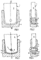
- the end of the upright 1 has a width less than that of the cavity 3, while the part of the upright external to the cavity 3 has a width greater than that of the opening of this cavity.
- This upright 1 can thus rest on its sides 5 against the corresponding edges of the opening of the cavity 3.
- the longitudinal dimension of the end of the upright engaged in the cavity 3 is such that this end does not touch the bottom of the cavity. It is thus possible to rotate the upright 1 relative to the branch 4 in order to orient it precisely in the desired position, for example that which appears in FIG. 3.
- the branch 4 is pierced transversely with a screw hole 6 and, when the amount is in the desired position relative to the branch 4, this amount is drilled with an identical screw hole opposite the hole 6. If the branch was not drilled in advance with a screw hole, the upright 1 and the branch 4 would be pierced simultaneously with screw holes arranged opposite, after having brought the upright 1 into the desired position.
- the end of the upright 1 is then removed from the cavity 3 and this cavity is filled with a monomer capable of polymerizing, giving a solid polymer, which adheres to the material of which the upright 1 and the branch 4 are made.
- a monomer capable of polymerizing giving a solid polymer, which adheres to the material of which the upright 1 and the branch 4 are made.
- the amount 1 is then reintroduced into the cavity 3, causing the overflow of the monomer to overflow, which is eliminated.
- the screw holes 6 and 7 are brought opposite one another, which has the effect of bringing the upright 1 into the precise position desired relative to the branch 4 of the joint, and, in this position ( Figure 3), the upright 1 and the branch 4 are secured with a screw 8 screwed into the holes 6 and 7.
- the means used to achieve this assembly in a relative position defined with precision of the amount 1 of the branch 4 of the joint are simple means, well known in the art, and this does not result in any increase in the cost of the orthosis thus carried out.
Landscapes
- Health & Medical Sciences (AREA)
- Engineering & Computer Science (AREA)
- Animal Behavior & Ethology (AREA)
- Veterinary Medicine (AREA)
- Biomedical Technology (AREA)
- Heart & Thoracic Surgery (AREA)
- Vascular Medicine (AREA)
- Life Sciences & Earth Sciences (AREA)
- Nursing (AREA)
- General Health & Medical Sciences (AREA)
- Public Health (AREA)
- Orthopedic Medicine & Surgery (AREA)
- General Engineering & Computer Science (AREA)
- Mechanical Engineering (AREA)
- Orthopedics, Nursing, And Contraception (AREA)
- Prostheses (AREA)
- Joining Of Building Structures In Genera (AREA)
- Food-Manufacturing Devices (AREA)
- Paper (AREA)
Description
- La présente invention concerne un nouveau système d'assemblage d'un montant et d'une articulation d'une orthèse des membres supérieurs ou inférieurs. L'invention concerne également un procédé pour la réalisation d'un tel système d'assemblage.
- On sait que de telles orthèses, utilisées au niveau du coude ou du genou des patients, comportent généralement deux montants longitudinaux, disposés à l'extérieur de chacun des membres (bras et avant-bras, ou jambe et cuisse) et réunis par des entretoises incurvées ou "embrasses" épousant le profil transversal du membre, chacun des montants associés aux bras et avant-bras ou à la cuisse et à la jambe étant articulés entre eux par une articulation comportant deux branches pivotantes autour d'un axe, cette articulation comportant éventuellement un élément de verrouillage en position.
- Les deux branches de l'articulation ont souvent la forme d'un fourreau, dans lequel est engagée l'extrémité correspondante du montant associé, la branche de l'articulation et le montant étant rendus rigidement solidaires l'un de l'autre à l'aide d'au moins une vis.
- Avant d'être rendus solidaires de l'articulation, chaque montant doit être orienté avec une grande précision par rapport à l'axe de celle-ci et, lorsqu'on emboîte simplement l'extrémité du montant dans le fourreau associé de l'articulation, la mise en position résultante est très souvent d'une précision insuffisante.
- La présente invention vise à remédier à cet inconvénient en proposant un système d'assemblage en une position relative précise des montants et des articulations d'une telle orthèse.
- L'invention a également pour but de proposer un système de ce type qui puisse être réalisé facilement à l'aide de moyens usuels dans la technique.
- L'invention vise enfin à proposer des orthèses comportant un tel système d'assemblage et présentant une grande résistance mécanique au niveau de l'assemblage des montants et des articulations.
- A cet effet, l'invention a pour objet un système d'assemblage d'un montant d'une orthèse des membres inférieurs ou supérieurs et d'une branche d'une articulation à deux branches montées pivotantes autour d'un axe l'une par rapport à l'autre, système dans lequel la branche de l'articulation forme un fourreau dans la cavité duquel est engagée l'extrémité du montant associé, cette extrémité et la branche du fourreau étant rendues rigidement solidaires l'une de l'autre par au moins une vis disposée perpendiculairement aux faces latérales des montants, ce système d'assemblage étant caractérisé en ce que l'extrémité du montant engagé dans la cavité du fourreau n'est pas en contact avec le fond de cette cavité, en ce que ses grandes faces ont une largeur inférieure à celle de la dimension correspondante de la cavité du fourreau, tandis que les mêmes faces de ce montant extérieures à cette cavité ont une largeur supérieure à celle de la dimension correspondante de l'ouverture du fourreau, afin que le montant prenne appui latéralement par ses flancs perpendiculaires aux grandes faces contre les parties correspondantes de l'ouverture du fourreau, et en ce que l'extrémité du montant engagée dans la cavité du fourreau est noyée dans un matériau adhésif solide emplissant cette cavité et adhérant aux surfaces internes de celle-ci et aux faces externes de l'extrémité du montant.
- Le montant de l'orthèse et la branche associée de l'articulation sont donc solidarisés, d'une part, par la vis de la technique antérieure, d'autre part, par le matériau adhésif solide, par exemple un polymère, une colle ou un ciment emplissant la cavité du fourreau. Du fait de cette double solidarisation, aucune contrainte de rupture ne s'exercera sur la vis. Par ailleurs, le montant venant buter latéralement par ses flancs contre les parties correspondantes de l'ouverture de la cavité alors que son extrémité ne touche pas le fond de cette cavité, il sera possible de l'orienter avec précision par rapport à la branche du fourreau, avant de le solidariser de celle-ci à l'aide d'au moins une vis et d'au moins un monomère liquide ou pâteux (une résine) dont on provoque ensuite la polymérisation.
- C'est ce qui ressort du procédé suivant de réalisation d'un tel système d'assemblage, qui constitue un autre objet de l'invention et qui comprend les phases successives suivantes :
- on engage dans la cavité de la branche formant fourreau de l'articulation, éventuellement percée transversalement d'un trou de vis, une extrémité du montant dont la largeur des grandes faces est inférieure à la dimension correspondante de la cavité, alors que les mêmes faces du montant extérieures à la cavité ont une largeur supérieure à la dimension correspondante de l'ouverture du fourreau, afin que le montant prenne appui par ses flancs perpendiculaires aux grandes faces contre les parties correspondantes de l'ouverture de la cavité, les dimensions de la partie engagée dans le fourreau étant telles que l'extrémité du montant ne touche pas le fond de la cavité ;
- on oriente avec précision le montant par rapport à la branche de l'articulation ;
- on perce des trous de vis disposés en regard dans le montant maintenu dans cette position et dans la branche formant fourreau de l'articulation, ou dans le montant seulement en regard du trou de vis que comporte déjà éventuellement la branche formant fourreau ;
- on retire du fourreau l'extrémité du montant ;
- on remplit la cavité du fourreau d'au moins un produit adhésif liquide ou pâteux, apte à durcir en formant un produit solide adhérant aux faces internes de la dite cavité ;
- on introduit à nouveau dans cette cavité l'extrémité du montant en éliminant de la cavité le trop-plein de produit liquide ou pâteux ;
- on amène en regard les trous de vis dont sont percés le montant et la branche formant fourreau de l'articulation ;
- on assemble par une vis engagée dans ces trous de vis l'extrémité du montant et la branche formant fourreau;
- on provoque le durcissement du produit liquide ou pâteux.
- Toutes ces opérations sont faciles à mettre en oeuvre et l'on peut donc ainsi réaliser une orthèse des membres inférieurs ou des membres supérieurs dont les montants sont orientés avec précision par rapport à l'articulation et qui présente une excellente résistance mécanique au niveau de l'assemblage des montants et de l'articulation.
- Les dessins shématiques annexés illustrent une forme de mise en oeuvre de l'invention . Sur ces dessins :
- La figure 1 est une vue partielle en élévation d'une extrémité d'un montant d'une orthèse engagée dans la cavité d'une branche formant fourreau d'une articulation de cette orthèse, en vue d'orienter avec précision ce montant par rapport à l'articulation ;
- La figure 2 est une coupe selon la ligne II - II de la figure 1 ;
- Les figures 3 et 4 sont des vues analogues après assemblage, conformément à l'invention, de l'extrémité du montant et de la branche formant fourreau de l'articulation.
- Comme on le voit sur les figures 1 et 2, l'extrémité d'un montant d'une orthèse comportant deux grandes faces parallèles 2 est engagée dans la cavité 3 d'une branche 4 formant fourreau d'une articulation de cette orthèse comportant deux branches analogues, articulées entre elles par un axe de rotation (non représenté) perpendiculaire aux grandes faces 2 des montants.
- L'extrémité du montant 1 a une largeur inférieure à celle de la cavité 3, tandis que la partie du montant extérieure à la cavité 3 a une largeur supérieure à celle de l'ouverture de cette cavité. Ce montant 1 peut ainsi prendre appui par ses flancs 5 contre les bords correspondants de l'ouverture de la cavité 3.
- La dimension longitudinale de l'extrémité du montant engagée dans la cavité 3 est telle que cette extrémité ne touche pas le fond de la cavité. Il est ainsi possible de faire pivoter le montant 1 par rapport à la branche 4 pour l'orienter avec précision dans la position désirée, par exemple celle qui apparaît sur la figure 3.
- La branche 4 est percée transversalement d'un trou de vis 6 et, lorsque le montant est dans la position souhaitée par rapport à la branche 4, on perce ce montant d'un trou de vis identique en regard du trou 6. Si la branche n'était pas percée à l'avance d'un trou de vis, on percerait simultanément le montant 1 et la branche 4 de trous de vis disposés en regard, après avoir amené le montant 1 dans la position désirée.
- On retire ensuite l'extrémité du montant 1 de la cavité 3 et l'on remplit cette cavité d'un monomère apte à polymériser en donnant un polymère solide, qui adhère au matériau dont sont constitués le montant 1 et la branche 4. On peut utiliser, par exemple, une résine époxy chargée de particules d'alumine, de particules métalliques ou autres.
- On réintroduit alors le montant 1 dans la cavité 3, en faisant déborder le trop-plein du monomère, que l'on élimine.
- On amène les trous de vis 6 et 7 en regard l'un de l'autre, ce qui a pour effet de ramener le montant 1 dans la position précise souhaitée par rapport à la branche 4 de l'articulation, et, dans cette position (figure 3) , on solidarise le montant 1 et la branche 4 à l'aide d'une vis 8 vissée dans les trous 6 et 7.
- On provoque enfin la polymérisation du monomère, et l'on obtient ainsi un double assemblage du montant 1 et de la branche de l'articulation, par la vis 8, d'une part , et par la polymére 9, d'autre part, ce qui assure une parfaite résistance mécanique de cet assemblage . On notera que, du fait du polymère, aucun effort de cisaillement ne s'exercera sur la vis 8.
- Les moyens utilisés pour réaliser cet assemblage en une position relative définie avec précision du montant 1 de la branche 4 de l'articulation sont des moyens simples, bien connus dans la technique, et il n'en résulte aucune majoration du coût de l'orthèse ainsi réalisée.
Claims (2)
- Système d'assemblage d'un montant (1) d'une orthèse des membres inférieurs ou supérieurs et d'une branche (4) d'une articulation à deux branches montées pivotantes autour d'un axe l'une par rapport à l'autre, système dans lequel la branche (1) de l'articulation forme un fourreau, dans la cavité (3) duquel est engagée l'extrémité du montant associé (1), cette extrémité et la branche du fourreau étant rendues rigidement solidaires l'une de l'autre par au moins une vis (8) disposée perpendiculairement aux faces latérales des montants, ce système d'assemblage étant caractérisé en ce que l'extrémité du montant (1) engagée dans la cavité (3) du fourreau n'est pas en contact avec le fond de cette cavité, en ce que ses grandes faces (2) ont une largeur inférieure à celle de la dimension correspondante de la cavité du fourreau, tandis que les mêmes faces (2) de ce montant extérieures à cette cavité ont une largeur supérieure à celle de la dimension correspondante de l'ouverture du fourreau, afin que le montant (1) prenne appui latéralement par ses flancs (5) perpendiculaires aux grandes faces (2) contre les parties correspondantes de l'ouverture du fourreau, et en ce que l'extrémité du montant engagé dans la cavité (3) du fourreau est noyée dans un matériau adhésif solide (9) emplissant cette cavité et adhérant aux surfaces internes de celle-ci et aux faces externes de l'extrémité du montant(1).
- Procédé pour la réalisation d'un système d'assemblage selon la revendication 1 d'un montant (1) d'une orthèse des membres inférieurs ou supérieurs et d'une branche (4) d'une articulation à deux branches montées pivotantes autour d'un axe l'une par rapport à l'autre, caractérisé par les phases successives suivantes:- on engage dans la cavité (3) de la branche (4) formant fourreau de l'articulation, éventuellement percée transversalement d'un trou de vis (6), une extrémité du montant (1) dont la largeur des grandes faces (2) est inférieure à la dimension correspondante de la cavité (3), alors que les mêmes faces (2) du montant (1) extérieures à la cavité (3) ont une largeur supérieure à la dimension correspondante de l'ouverture du fourreau, afin que le montant prenne appui par ses flancs (5) perpendiculaires aux grandes faces (2) contre les parties correspondantes de l'ouverture de la cavité, les dimensions de la partie engagée dans le fourreau étant telles que l'extrémité du montant (1) ne touche pas le fond de la cavité (3) ;- on oriente avec précision le montant (1) par rapport à la branche (4) de l'articulation ;- on perce des trous de vis (7) disposés en regard dans le montant maintenu dans cette position et dans la branche formant fourreau de l'articulation, ou dans le montant seulement en regard du trou de vis (6) que comporte déjà éventuellement la branche formant fourreau ;- on retire du fourreau l'extrémité du montant (1) ;- on remplit la cavité (3) du fourreau d'au moins un produit liquide et pâteux apte à durcir en formant un produit solide adhérant aux faces internes de la dite cavité ;- on introduit à nouveau dans cette cavité (3)l'extrémité du montant (1) en éliminant de la cavité le trop plein de produit liquide ou pâteux ;- on amène en regard les trous de vis (6,7) dont sont percés le montant et la branche formant fourreau de l'articulation ;- on assemble par une vis (8) engagée dans ces trous de vis l'extrémité du montant (1) et la branche (4) formant fourreau;- on provoque le durcissement du produit liquide ou pâteux.
Priority Applications (1)
| Application Number | Priority Date | Filing Date | Title |
|---|---|---|---|
| AT91400962T ATE100697T1 (de) | 1990-05-10 | 1991-04-10 | System und verfahren zum zusammenbau einer orthese. |
Applications Claiming Priority (2)
| Application Number | Priority Date | Filing Date | Title |
|---|---|---|---|
| FR9005817 | 1990-05-10 | ||
| FR9005817A FR2661818B1 (fr) | 1990-05-10 | 1990-05-10 | Nouveau systeme d'assemblage d'un montant et d'une articulation d'une orhtese des membres superieurs ou inferieurs et procede pour la realisation d'un tel systeme d'assemblage. |
Publications (2)
| Publication Number | Publication Date |
|---|---|
| EP0456534A1 EP0456534A1 (fr) | 1991-11-13 |
| EP0456534B1 true EP0456534B1 (fr) | 1994-01-26 |
Family
ID=9396459
Family Applications (1)
| Application Number | Title | Priority Date | Filing Date |
|---|---|---|---|
| EP91400962A Expired - Lifetime EP0456534B1 (fr) | 1990-05-10 | 1991-04-10 | Système d'assemblage d'une orthèse et procédé de réalisation |
Country Status (4)
| Country | Link |
|---|---|
| EP (1) | EP0456534B1 (fr) |
| AT (1) | ATE100697T1 (fr) |
| DE (1) | DE69101077T2 (fr) |
| FR (1) | FR2661818B1 (fr) |
Families Citing this family (1)
| Publication number | Priority date | Publication date | Assignee | Title |
|---|---|---|---|---|
| CN111015543B (zh) * | 2019-11-25 | 2021-04-20 | 北京北机机电工业有限责任公司 | 一种筒形零件粘接工装 |
Family Cites Families (3)
| Publication number | Priority date | Publication date | Assignee | Title |
|---|---|---|---|---|
| US4561670A (en) * | 1982-05-28 | 1985-12-31 | Honda Giken Kogyo Kabushiki Kaisha | Frame for automated two-wheel vehicles, and method for its manufacture |
| US4502472A (en) * | 1983-09-12 | 1985-03-05 | Pansiera Timothy T | Hinge means for orthopedic brace |
| DE3635031A1 (de) * | 1986-10-15 | 1988-04-21 | Halberg Maschbau Gmbh & Co | Verfahren zum verbinden von gussstuecken |
-
1990
- 1990-05-10 FR FR9005817A patent/FR2661818B1/fr not_active Expired - Lifetime
-
1991
- 1991-04-10 EP EP91400962A patent/EP0456534B1/fr not_active Expired - Lifetime
- 1991-04-10 DE DE69101077T patent/DE69101077T2/de not_active Expired - Fee Related
- 1991-04-10 AT AT91400962T patent/ATE100697T1/de not_active IP Right Cessation
Also Published As
| Publication number | Publication date |
|---|---|
| ATE100697T1 (de) | 1994-02-15 |
| DE69101077D1 (de) | 1994-03-10 |
| DE69101077T2 (de) | 1994-05-26 |
| FR2661818A1 (fr) | 1991-11-15 |
| EP0456534A1 (fr) | 1991-11-13 |
| FR2661818B1 (fr) | 1992-10-30 |
Similar Documents
| Publication | Publication Date | Title |
|---|---|---|
| FR2557668A1 (fr) | Assemblage d'un connecteur, element tubulaire et procede de realisation d'un raccord entre deux elements tubulaires | |
| FR2714709A1 (fr) | Accouplement à ouverture d'urgence alimenté par une double vanne à boisseau sphérique à débordement nul. | |
| FR2640499A1 (fr) | Nouvelle structure de pied prothetique | |
| FR2467348A1 (fr) | Raccord de canalisation comprenant un collier a chaine | |
| FR2965199A1 (fr) | Bride d'aide au travail de tubes comportant plusieurs parties. | |
| EP3851725B1 (fr) | Collier comprenant un système de réglage de diamètre configuré pour autoriser un changement de diamètre du collier | |
| FR2483540A1 (fr) | Verin pneumatique ou hydraulique | |
| FR3053956B1 (fr) | Gouverne crocodile pour aeronef | |
| EP0456534B1 (fr) | Système d'assemblage d'une orthèse et procédé de réalisation | |
| WO1992007144A1 (fr) | Procede de construction d'ouvrages d'art comprenant une voute et elements prefabriques pour la mise en ×uvre de ce procede | |
| FR2587971A1 (fr) | Rotor, en particulier pour aeronef a voilure tournante | |
| FR2640336A1 (fr) | Ecrou rapide | |
| EP0220095B1 (fr) | Procédé et dispositif de redressement et d'alignement d'une première pièce en matière plastique par exemple thermosoudable avec une deuxième pièce en matière plastique similaire pouvant également être redressée en vue de leur assemblage bout à bout | |
| FR2564019A1 (fr) | Pince d'alignement interne | |
| FR2581717A1 (fr) | Raccord pour l'assemblage angulaire d'organes tubulaires | |
| EP0124430B1 (fr) | Dispositif de raccordement télédémontable | |
| EP0262998A1 (fr) | Dispositif pour le perçage de panneaux de bois en vue de leur assemblage par chevilles | |
| FR2684062A1 (fr) | Fourche de bicyclette et procede de fabrication d'une telle fourche. | |
| EP0049645A2 (fr) | Assemblage en T et procédé pour l'obtenir | |
| FR2638088A1 (fr) | Dispositif pour relever la configuration d'un membre inferieur du corps humain en vue de la realisation d'une orthese pour paraplegique | |
| EP0410842A1 (fr) | Raccord rapide | |
| EP0953778A1 (fr) | Dispositif écrou de mise en place rapide, à deux demi-écrous, et agencement de blocage notamment pour coffrage de béton, utilisant un tel dispositif écrou | |
| FR2660351A1 (fr) | Coffrage reutilisable pour pilier ou analogue et son procede de fabrication. | |
| EP0217901A1 (fr) | Coupleur-decoupleur a verrouillage de securite et a ouverture assistee par verin | |
| WO1985000634A1 (fr) | Pince de puissance pour le vissage des tiges de forage |
Legal Events
| Date | Code | Title | Description |
|---|---|---|---|
| PUAI | Public reference made under article 153(3) epc to a published international application that has entered the european phase |
Free format text: ORIGINAL CODE: 0009012 |
|
| AK | Designated contracting states |
Kind code of ref document: A1 Designated state(s): AT BE DE GB IT NL SE |
|
| 17P | Request for examination filed |
Effective date: 19920206 |
|
| 17Q | First examination report despatched |
Effective date: 19930712 |
|
| GRAA | (expected) grant |
Free format text: ORIGINAL CODE: 0009210 |
|
| AK | Designated contracting states |
Kind code of ref document: B1 Designated state(s): AT BE DE GB IT NL SE |
|
| REF | Corresponds to: |
Ref document number: 100697 Country of ref document: AT Date of ref document: 19940215 Kind code of ref document: T |
|
| GBT | Gb: translation of ep patent filed (gb section 77(6)(a)/1977) |
Effective date: 19940209 |
|
| REF | Corresponds to: |
Ref document number: 69101077 Country of ref document: DE Date of ref document: 19940310 |
|
| ITF | It: translation for a ep patent filed | ||
| PLBE | No opposition filed within time limit |
Free format text: ORIGINAL CODE: 0009261 |
|
| STAA | Information on the status of an ep patent application or granted ep patent |
Free format text: STATUS: NO OPPOSITION FILED WITHIN TIME LIMIT |
|
| 26N | No opposition filed | ||
| EAL | Se: european patent in force in sweden |
Ref document number: 91400962.6 |
|
| REG | Reference to a national code |
Ref country code: GB Ref legal event code: IF02 |
|
| PGFP | Annual fee paid to national office [announced via postgrant information from national office to epo] |
Ref country code: GB Payment date: 20030415 Year of fee payment: 13 |
|
| PGFP | Annual fee paid to national office [announced via postgrant information from national office to epo] |
Ref country code: SE Payment date: 20030417 Year of fee payment: 13 |
|
| PGFP | Annual fee paid to national office [announced via postgrant information from national office to epo] |
Ref country code: AT Payment date: 20030418 Year of fee payment: 13 |
|
| PGFP | Annual fee paid to national office [announced via postgrant information from national office to epo] |
Ref country code: NL Payment date: 20030423 Year of fee payment: 13 |
|
| PGFP | Annual fee paid to national office [announced via postgrant information from national office to epo] |
Ref country code: BE Payment date: 20030512 Year of fee payment: 13 |
|
| PG25 | Lapsed in a contracting state [announced via postgrant information from national office to epo] |
Ref country code: GB Free format text: LAPSE BECAUSE OF NON-PAYMENT OF DUE FEES Effective date: 20040410 Ref country code: AT Free format text: LAPSE BECAUSE OF NON-PAYMENT OF DUE FEES Effective date: 20040410 |
|
| PG25 | Lapsed in a contracting state [announced via postgrant information from national office to epo] |
Ref country code: SE Free format text: LAPSE BECAUSE OF NON-PAYMENT OF DUE FEES Effective date: 20040411 |
|
| PG25 | Lapsed in a contracting state [announced via postgrant information from national office to epo] |
Ref country code: BE Free format text: LAPSE BECAUSE OF NON-PAYMENT OF DUE FEES Effective date: 20040430 |
|
| BERE | Be: lapsed |
Owner name: ETS *PROTEOR Effective date: 20040430 |
|
| PG25 | Lapsed in a contracting state [announced via postgrant information from national office to epo] |
Ref country code: NL Free format text: LAPSE BECAUSE OF NON-PAYMENT OF DUE FEES Effective date: 20041101 |
|
| EUG | Se: european patent has lapsed | ||
| GBPC | Gb: european patent ceased through non-payment of renewal fee |
Effective date: 20040410 |
|
| NLV4 | Nl: lapsed or anulled due to non-payment of the annual fee |
Effective date: 20041101 |
|
| PG25 | Lapsed in a contracting state [announced via postgrant information from national office to epo] |
Ref country code: IT Free format text: LAPSE BECAUSE OF NON-PAYMENT OF DUE FEES;WARNING: LAPSES OF ITALIAN PATENTS WITH EFFECTIVE DATE BEFORE 2007 MAY HAVE OCCURRED AT ANY TIME BEFORE 2007. THE CORRECT EFFECTIVE DATE MAY BE DIFFERENT FROM THE ONE RECORDED. Effective date: 20050410 |
|
| PGFP | Annual fee paid to national office [announced via postgrant information from national office to epo] |
Ref country code: DE Payment date: 20070423 Year of fee payment: 17 |
|
| PG25 | Lapsed in a contracting state [announced via postgrant information from national office to epo] |
Ref country code: DE Free format text: LAPSE BECAUSE OF NON-PAYMENT OF DUE FEES Effective date: 20081101 |