EP0456577B1 - Verfahren und Vorrichtung zur Herstellung von Kernbrennstabbündelabstandshaltern - Google Patents
Verfahren und Vorrichtung zur Herstellung von Kernbrennstabbündelabstandshaltern Download PDFInfo
- Publication number
- EP0456577B1 EP0456577B1 EP91401203A EP91401203A EP0456577B1 EP 0456577 B1 EP0456577 B1 EP 0456577B1 EP 91401203 A EP91401203 A EP 91401203A EP 91401203 A EP91401203 A EP 91401203A EP 0456577 B1 EP0456577 B1 EP 0456577B1
- Authority
- EP
- European Patent Office
- Prior art keywords
- grid
- chamber
- welds
- frame
- laser
- Prior art date
- Legal status (The legal status is an assumption and is not a legal conclusion. Google has not performed a legal analysis and makes no representation as to the accuracy of the status listed.)
- Expired - Lifetime
Links
Images





Classifications
-
- B—PERFORMING OPERATIONS; TRANSPORTING
- B23—MACHINE TOOLS; METAL-WORKING NOT OTHERWISE PROVIDED FOR
- B23K—SOLDERING OR UNSOLDERING; WELDING; CLADDING OR PLATING BY SOLDERING OR WELDING; CUTTING BY APPLYING HEAT LOCALLY, e.g. FLAME CUTTING; WORKING BY LASER BEAM
- B23K26/00—Working by laser beam, e.g. welding, cutting or boring
- B23K26/12—Working by laser beam, e.g. welding, cutting or boring in a special environment or atmosphere, e.g. in an enclosure
- B23K26/123—Working by laser beam, e.g. welding, cutting or boring in a special environment or atmosphere, e.g. in an enclosure in an atmosphere of particular gases
-
- B—PERFORMING OPERATIONS; TRANSPORTING
- B23—MACHINE TOOLS; METAL-WORKING NOT OTHERWISE PROVIDED FOR
- B23K—SOLDERING OR UNSOLDERING; WELDING; CLADDING OR PLATING BY SOLDERING OR WELDING; CUTTING BY APPLYING HEAT LOCALLY, e.g. FLAME CUTTING; WORKING BY LASER BEAM
- B23K26/00—Working by laser beam, e.g. welding, cutting or boring
- B23K26/08—Devices involving relative movement between laser beam and workpiece
-
- B—PERFORMING OPERATIONS; TRANSPORTING
- B23—MACHINE TOOLS; METAL-WORKING NOT OTHERWISE PROVIDED FOR
- B23K—SOLDERING OR UNSOLDERING; WELDING; CLADDING OR PLATING BY SOLDERING OR WELDING; CUTTING BY APPLYING HEAT LOCALLY, e.g. FLAME CUTTING; WORKING BY LASER BEAM
- B23K26/00—Working by laser beam, e.g. welding, cutting or boring
- B23K26/08—Devices involving relative movement between laser beam and workpiece
- B23K26/0869—Devices involving movement of the laser head in at least one axial direction
- B23K26/0876—Devices involving movement of the laser head in at least one axial direction in at least two axial directions
-
- B—PERFORMING OPERATIONS; TRANSPORTING
- B23—MACHINE TOOLS; METAL-WORKING NOT OTHERWISE PROVIDED FOR
- B23K—SOLDERING OR UNSOLDERING; WELDING; CLADDING OR PLATING BY SOLDERING OR WELDING; CUTTING BY APPLYING HEAT LOCALLY, e.g. FLAME CUTTING; WORKING BY LASER BEAM
- B23K26/00—Working by laser beam, e.g. welding, cutting or boring
- B23K26/12—Working by laser beam, e.g. welding, cutting or boring in a special environment or atmosphere, e.g. in an enclosure
-
- B—PERFORMING OPERATIONS; TRANSPORTING
- B23—MACHINE TOOLS; METAL-WORKING NOT OTHERWISE PROVIDED FOR
- B23K—SOLDERING OR UNSOLDERING; WELDING; CLADDING OR PLATING BY SOLDERING OR WELDING; CUTTING BY APPLYING HEAT LOCALLY, e.g. FLAME CUTTING; WORKING BY LASER BEAM
- B23K26/00—Working by laser beam, e.g. welding, cutting or boring
- B23K26/12—Working by laser beam, e.g. welding, cutting or boring in a special environment or atmosphere, e.g. in an enclosure
- B23K26/127—Working by laser beam, e.g. welding, cutting or boring in a special environment or atmosphere, e.g. in an enclosure in an enclosure
-
- G—PHYSICS
- G21—NUCLEAR PHYSICS; NUCLEAR ENGINEERING
- G21C—NUCLEAR REACTORS
- G21C3/00—Reactor fuel elements and their assemblies; Selection of substances for use as reactor fuel elements
- G21C3/30—Assemblies of a number of fuel elements in the form of a rigid unit
- G21C3/32—Bundles of parallel pin-, rod-, or tube-shaped fuel elements
- G21C3/34—Spacer grids
- G21C3/3424—Fabrication of spacer grids
-
- Y—GENERAL TAGGING OF NEW TECHNOLOGICAL DEVELOPMENTS; GENERAL TAGGING OF CROSS-SECTIONAL TECHNOLOGIES SPANNING OVER SEVERAL SECTIONS OF THE IPC; TECHNICAL SUBJECTS COVERED BY FORMER USPC CROSS-REFERENCE ART COLLECTIONS [XRACs] AND DIGESTS
- Y02—TECHNOLOGIES OR APPLICATIONS FOR MITIGATION OR ADAPTATION AGAINST CLIMATE CHANGE
- Y02E—REDUCTION OF GREENHOUSE GAS [GHG] EMISSIONS, RELATED TO ENERGY GENERATION, TRANSMISSION OR DISTRIBUTION
- Y02E30/00—Energy generation of nuclear origin
- Y02E30/30—Nuclear fission reactors
Definitions
- the subject of the invention is a method and a device for manufacturing grids intended to be incorporated into fuel assemblies for a nuclear reactor. It finds a particularly important application in the manufacture of grids intended for assemblies whose framework comprises end pieces connected by guide tubes trapped in some of the grid cells regularly distributed along the guide tubes, the other grid cells supporting the fuel rods of the assembly.
- Grids have also been provided, in particular with a view to assemblies for a sub-moderate reactor, which have a hexagonal section and which comprise three sets of interleaved plates.
- the invention although particularly advantageous in the case of grids whose large faces have a square shape and whose cells are distributed at the nodes of a square network, also applies to grids whose large faces have a hexagonal shape.
- the invention relates to a method and a device of the type described in document FR-A-2 522 560, in accordance with the preambles of claims 1 and 8.
- any oxidation of the welds is avoided, which makes it possible in particular to apply the process not only to grids made of high-strength alloy, such as INCONEL, but also to grids whose components are made of a zirconium-based alloy.
- the protective atmosphere is obtained by scanning, which implies significant losses of inert gas.
- the laser generator is kept fixed during the welding of a face, except for the welds carried out on the belt, for which the beam is deflected using a set of mirrors.
- the variety of precise movements of the grids inside the chamber does not guarantee sufficient precision to be compatible with the very small size of the focal spot of the laser beam.
- the room must have a very large volume.
- the documents FR-A-2 532 216 and EP-A-0 102 252 also describe a welding process using a fixed laser generator.
- the laser beam is directed and focused in an open chamber, subjected to an argon scan, in which a grid is animated with orthogonal movements of displacement.
- This process requires very large gas flow rates, the capture of polluted gases by laser shots is difficult and checking leaks from the open chamber requires very small clearances, which are difficult to achieve.
- US-A-4,710,606 describes a welding robot in which a laser beam must be moved according to five degrees of freedom by mirrors, which implies a great complexity of the mechanism and an accumulation of tolerances.
- document EP-A-0 168 673 describes a welding installation with a single laser generator and two welding chambers used alternately.
- the invention aims in particular to provide a method and an installation for welding grids by laser beam of the type defined above, making it possible to carry out, in sequence and automatically the necessary welds under conditions ensuring the mechanical retention of the parts and the absence of deformations and oxidation, while avoiding complex displacements such as to affect the accuracy of the welding due to a plurality of clearances.
- the invention proposes in particular a method of the type defined above, in accordance with claim 1.
- This process judiciously distributes the movements between the laser beam, the necessary focusing optics and the frame.
- welds are carried out on the same plane, that is to say without modifying the distance to the laser generator, except for particular welds, such as the grid welds.
- the unloading of a grid, the loading of another grid to be welded and the placing in an inert atmosphere of a chamber can be carried out during the welding of the grid occupying the other chamber, that is to say in masked time.
- the inert gas will be placed in an atmosphere by pumping the chamber until a primary vacuum is obtained, then filling with inert gas so that the atmosphere in which it takes place welding contains less than 50 vpm of oxygen.
- the portholes from alternating pressure stresses they can be protected by covers during evacuation.
- the optical path of the laser beam can be defined by optical means, such as mirrors or lenses, vibrated.
- the vibrations of the focusing lens are then synchronized with the pulsations of the laser, so that each shot occurs while the optical path is oriented towards the point which must receive the energy.
- the invention also proposes an installation for securing by laser welding of the various parts constituting a grid, according to claim 8.
- Other characteristics are also the subject of the dependent claims.
- the installation which will now be described makes it possible in particular to secure by welding the constituent parts of a grid 1 of the kind shown in FIG. 1, which may have the detailed constitution described in document EP-A-0 159 228 or FR-A-2 474 229.
- the grid 1 comprises two intertwined sets of elementary plates 2 assembled at half-iron.
- a joining weld 3, called “type A”, the detail of which is indicated in FIG. 1A, secures the plates at each intersection, on each of the two large faces of the grid 1.
- the edges of the plates 2 form, with peripheral plates 5 constituting the belt, a T-shaped intersection which receives, on each face, a weld 4, called "type B", shown in Figure 1B.
- the plates 2 have at their ends, tenons which engage in mortises made in the plates 5 of the belt. Each end may in particular comprise two or three tenons 7 engaging in respective mortises 8 ( Figure 1C). These studs, some of which can be deformed to achieve mechanical locking, are fixed by edge welds called "type C".
- weld beads 9 secure the elements of the belt by connecting fallen edges 10 formed at the ends of the peripheral plates 5. These welds, shown in FIG. 1D, are said to be "of type D". "Type D” welds can be replaced with edge-to-edge welds, as shown in Figure 1DD.
- the plates constituting the grid are joined not by overlap welding, but by edge-to-edge welding at an internal plate 2 (Figure 1E).
- This type of welding is generally carried out at the level of the second internal plate starting from a corner of the grid, so as to allow shaping of the plate defining the cell located at the corner of the grid.
- each assembled grid is first put in a frame intended to maintain the components of the grid in a well-determined position and to constitute a manipulable assembly which can be brought into all the directions required for welding.
- the frame may have the constitution described in document EP-A-0 159 228, to which reference may be made.
- the installation is contained in a cell 11, the front face of which is equipped with movable transparent panels allowing access to the enclosure for loading / unloading.
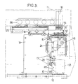
- the installation comprises a support structure having a beam 12 which supports cabinets containing the power supply means and the circuits for regulating and controlling the welding operations according to a pre-recorded program and a frame 14 which carries the various mobile components. .
- On this frame 14 are fixed slides 15 ( Figures 2 to 4), arranged horizontally in a direction X, on which move a main carriage 21 and an auxiliary carriage 22 placed below. These carriages are connected by an arm 24.
- the main carriage 21 carries two adjoining welding chambers 16 and 17, each having a door before insertion and removal of the grids.
- the auxiliary carriage 22 carries the chambers for conditioning the atmosphere of the chambers and in particular the vacuum pump.
- the carriages 21 and 22 are movable along the X axis. Their drive is ensured by a jack and their precise positioning by stops with shock absorbers.
- each of the chambers 16 and 17 has a transparent window for welding radiation.
- This radiation is provided by a laser source carried by a table with crossed movements in the direction X and the horizontal direction Y orthogonal to X.
- the laser generator can be viewed as comprising a laser proper 20 and an optic 18 for returning in the vertical direction Z and focusing at adjustable distance.
- the laser can be carried by a cradle 26 fixed to the upper plate 25 of the cross-motion table 19.
- the chamber 16 is provided with a device 27 for orientation around an axis parallel to the direction Y, intended to receive a grid contained in its frame for carrying out the welds of types C and of type D (or DD or E ).
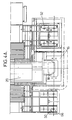
- This chamber is shown in Figure 4 in a position where its inlet porthole is located under the area scanned by the movement of the laser beam, for the execution of the welds of the grid contained in the chamber.
- the rear wall of the chamber 16 is crossed by the plate 35 of the device 27 which makes it possible to maintain a grid contained in its frame and to give it the eight orientations required to carry out type C welds (and, optionally, E), thus than type D or DD welds, when they exist on the four corners of the grid.
- the device 27 is intended to bring the grid in the four orientations required to allow the execution of the welds. C, and possibly E, on the four sides of the belt and, in other cases, the four additional orientations necessary for the execution of the welds on the corners of the grid.
- the large faces of the grid will be parallel to the direction Z, that is to say to the path of the laser beam during welding.
- the adjustment of the working distance makes it possible to execute both type C weld points, as well as type D or DD weld beads, when the latter are provided.
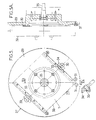
- the orientation device 27 comprises a circular plate 29 fitted with cams 30 for fixing the template frame 32 containing a grid, the periphery of which is shown diagrammatically in dashes in FIGS. 4, 5 and 5A.
- the two cams 30 make it possible to apply the frame against positioning pins 31 and against the plate.
- the pivoting part of the frames pivots in crescent grooves 33 provided on the frame.
- the plate 29 is fixed on the disc 35, secured by the output shaft to a not shown rotational drive motor, equipped with an encoder giving an orientation indication to the cabinets 13.
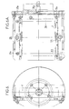
- the chamber 17 is also equipped with an orientation device 28, shown in Figures 6 and 6A.
- This device includes its own plate 29 fixed to a disk 35 has orientation about an axis parallel to the direction Y.
- the tray 29 is for receiving the template-frame in a position where the large faces of the grid and two of the sides are parallel to the orientation axis.
- the plate 29 a consists of a plate fixed directly to the disc 35 and a base 36 carrying the cams 30 a and the pins 31 a , orthogonal to the plate.
- an opening 37 of sufficient size to give access to all the welding points to be executed on the large face of the grid which faces the base.
- the laser source can in particular have the constitution shown diagrammatically in FIG. 7.
- the beam supplied by the laser 20 is returned by a dichroic mirror 38 to the focusing optic 18 made up of several lenses.
- This set of lenses is mounted in a motorized frame and movable along the Z axis along a stroke of 200 mm, so as to be able to adjust the working distance as well as possible whatever the welds to be produced.
- the image of the location to be welded, taken up by the optic 18 and passing through the dichroic mirror 38, is captured by a CCD camera which transmits this image to a monitor integral with the control console.
- the operator can then focus using a mechanism not shown so that obtaining a clear image in visible light indicates a correct working distance.
- the movements along the Z axis of the optics 18 being controlled by the control electronics, the adjustment of the working distance is in fact carried out automatically.
- the optic 18 can have the constitution shown in FIG. 8.
- This optic 18 comprises a frame supporting three lenses, 40, 42 and 44.
- the lens 44 focuses the beam on the point to be welded.
- the lens 44 is mounted on a slide which allows it to oscillate in the direction X with an amplitude corresponding to the desired distance between the weld points to be made to make the welds of type C, D or E.
- the amplitude of movement can for example be adjustable from 0 to 2 mm.
- the oscillation movement is ensured by means of electromagnets moving the slide against adjustable stops.
- the box shown in Figure 8 also includes means for lighting the location where the shot is to be taken, constituted by a lens 46 for focusing the output beam of two optical fibers 48 supplied with light by a generator not shown.
- the two chambers 16 and 17 are fixed and the cross-motion table is mounted on means making it possible to bring the laser generator successively above the chamber 16 and above the room 17.
- the installation is advantageously provided for replacing the air with this gas not by sweeping, but by evacuation then filling.
- Vacuuming seems at first glance to be excluded, since glass portholes would not withstand the pressure forces applied during vacuuming.
- the covers 50 and 52 are intended to be used alternately, and to be applied against the porthole of the chamber which is not in alignment with the optics of the laser.
- the covers 50 and 52 are connected to a support frame 54 via respective control mechanisms.
- the mechanism shown schematically in Figures 3, 4 and 9 includes airbags 56 interposed between a support plate 57 secured to the chassis and a pad 58 fixed to the covers.
- the pads are guided by rods 60 sliding in the support plate 57 and solicited towards a high position by springs 62.
- the downward movement of the pads 58 and covers is limited by the support of nuts 64, screwed onto a terminal threaded part of the rods 60, against the plates 57.
- Each porthole is provided with several balancing valves occupying for example the locations indicated at 66 in FIG. 4A, for one of the portholes.
- Each valve comprises a passage formed in the wall of the chamber, part of which is limited by a seat 68.
- This seat is designed to receive an opturizer 70, pushed back by a spring 72 towards its closed position.
- the shutter 70 In the closed position, the shutter 70 has a protruding part above the wall of the chamber.
- This wall carries an annular seal 74 surrounding all of the valves.
- the assembled grid plates are first placed in the frame which constitutes a template keeping these plates in a well-determined position.
- a first sequence of operations is intended to perform the welds on the belt.
- the frame 32 containing the grid is placed on the plate 29 in the chamber 16 and locked using the cams 30.
- the chamber 16 is closed.
- the protective cover of the porthole of the chamber 16 is applied against the wall of the chamber to balance the pressures on either side of the porthole.
- the interior of the chamber is brought into primary vacuum using the pump of the conditioning device 23, then filled with argon. Two pumping and filling sequences are sufficient to achieve a sufficiently pure atmosphere, including the oxygen content is less than 50 vpm and the water content is less than 150 vpm.
- the cover can then be lifted.
- the overpressure in the chamber can be 40 mbar and maintained with an argon flow of 20 to 60 l / min makes it possible to evacuate the welding fumes appearing in the chamber.
- the installation advantageously includes means for analyzing the argon which leaves through a vent, making it possible to verify that the oxygen and humidity contents do not exceed the thresholds indicated above.
- the type C and D (or E) welds can be performed automatically.
- the laser is directed to each welding location using the cross-motion table 19.
- type D or E welds type D welds requiring a different working distance than type E welds.
- Each weld can be carried out by adding energy between 14 and 22 Joules per pulse, at a rate of 7 to 16 Hz, the pulse duration being approximately 5 ms.
- Type C welds can be performed with parameters of the same order as those required for bead D and E welds.
- the carriages 21 and 22 are moved on their slides, automatically, under the control of the electronics contained in the cabinets 13. Following this movement, the porthole of chamber 17 is under the optic 18. Chamber 16 is then opened and the grid which occupied it is removed and replaced by a new grid, while type A and B welds are carried out.
- Each weld requires displacements of the laser generator by the table 19 in the two directions X and Y.
- Each weld can be carried out in general by one or two pulses of duration of approximately 5 ms, carried out at a frequency of 5 to 10 Hz and with a total energy of 14 to 24 Joules per pulse.
- the welds are carried out first on a large face, then on the other, after rotation of the plate 29 a by 180 °.
Landscapes
- Engineering & Computer Science (AREA)
- Physics & Mathematics (AREA)
- Optics & Photonics (AREA)
- Plasma & Fusion (AREA)
- Mechanical Engineering (AREA)
- General Engineering & Computer Science (AREA)
- High Energy & Nuclear Physics (AREA)
- Laser Beam Processing (AREA)
Claims (10)
- Verfahren zur Herstellung eines Abstandshalters für Brennstabbündel von Kernreaktoren mit folgenden Schritten:
der Abstandshalter (1), dessen Bestandteile (2,5) fest miteinander zu verbinden sind, wird in einem mechanischen Montage- und Stützrahmen angebracht, der Zugangsmöglichkeiten zu den Schweißstellen auf den beiden Hauptflächen und den Seiten des Halters aufweist;
der Rahmen mit dem darin befindlichen Halter wird mit Hilfe einer ersten Ausrichtevorrichtung um eine erste Achse, die sich in einer dichten, mit einer Inertgasatmosphäre befüllten ersten Kammer (16) befindet, gefaßt; die Schweißpunkte auf einer Fläche werden auf einmal mit einem zur Ausrichteachse der Vorrichtung orthogonalen Laserstrahl angebracht, der von einer Laserquelle stammt, die außerhalb der Kammer angebracht ist und der in diese durch eine transparente Scheibe eindringt, anschließend wird der Vorgang an der anderen Fläche wiederholt,
dadurch gekennzeichnet, daß
im Verlauf des Schweißvorgangs auf einer Fläche des Halters der Laserstrahl in zwei zueinander und zu der Strahlungsrichtung des Laserstrahls orthogonalen Richtungen verschoben wird, während der Rahmen in der ersten Kammer (16) starr fixiert bleibt, und, bevor der Vorgang auf einer anderen Fläche wiederholt wird, der Halter mit Hilfe der ersten Vorrichtung um die Achse gedreht wird, die zur Strahlungsrichtung des Laserstrahls orthogonal ist, bis alle Schweißpunkte auf den zur ersten Achse parallelen Flächen angebracht sind;
anschließend der immmer noch in seinem Rahmen befindliche Halter in eine zweite Kammer (17) eingebracht wird, die mit einer zweiten Ausrichtevorrichtung (28) um eine zweite Achse, die zu der ersten parallel ist, versehen ist, aber in der der Halter in einer Richtung angebracht wird, die zu der parallel ist, die von ihm in der ersten Vorrichtung eingenommen wurde, und
die Schweißpunkte auf den Hauptflächen des Halters angebracht werden, wobei jedes Mal der Rahmen starr fixiert ist. - Verfahren nach Anspruch 1, dadurch gekennzeichnet, daß die Entnahme eines Halters, das Einbringen eines anderen, zu verschweißenden Halters und das Versehen einer Kammer (16, 17) mit einer Inertgasatmosphäre während des Verschweißens des in der anderen Kammer (17, 16) befindlichen Halters durchgeführt wird.
- Verfahren nach Anspruch 1 oder 2, dadurch gekennzeichnet, daß alle Schweißpunkte ohne Änderung des Abstands zu der Laserquelle (20-18) und ohne Änderung der Position des Focussierlinse in Richtung der Achse Z des Laserstrahls angebracht werden, außer für die Schweißpunkte eines Eckstücks einer Außenwand des Halters.
- Verfahren nach einem der Ansprüche 1, 2 oder 3, dadurch gekennzeichnet, daß die Schweißvorgänge in der ersten Kammer (16) durchgeführt werden, während diese in einer Position ist, in der sich die Scheibe unter der Optik der Laserquelle befindet und anschließend die beiden Kammern (16, 17) so verschoben werden, daß die Scheibe der zweiten Kammer unter diese Optik gebracht wird, um das Verschweißen der Hauptflächen durchzuführen.
- Verfahren nach einem der vorhergehenden Ansprüche, dadurch gekennzeichnet, daß bestimmte Schweißpunkte mit Laserschüssen angebracht werden, die auf zwei in einer geringen Distanz zueinander auf zwei parallelen Linien liegende Punkte gebündelt sind.
- Verfahren nch Anspruch 5, dadurch gekennzeichnet, daß der Lichtweg des Laserstrahls durch hin-und herschwingende optische Mittel definiert wird und die Schwingvorgänge so mit den Laserschüssen synchronisiert sind, daß jeder Impuls dann abgegeben wird, während der Lichtweg auf den Punkt gerichtet ist, der die Energie erhalten muß.
- Verfahren nach einem der vorhergehenden Ansprüche, dadurch gekennzeichnet, daß vor dem Anbringen der Schweißpunkte ein Deckel (50, 52) auf die Scheibe gelegt und die Drücke auf der einen und der anderen Seite der Abdeckung angeglichen werden und die dichte Kammer (16, 17) unter Beibehalten des Druckausgleichs evakuiert und mit einer Inertgasatmosphäre versehen wird, bevor der Druckausgleich unterbrochen und der Deckel (50, 52) abgenommen wird.
- Vorrichtung zum festen Verbinden verschiedener Bestandteile eines Abstandshalters durch Laserschweißen mit einem Laserschweißgenerator (20, 18) und einer ersten Kammer (16) mit einstellbarer Atmosphäre, die eine transparente Scheibe besitzt und mit einer ersten Ausrichtevorrichtung um eine erste Achse versehen ist, die zur Aufnahme eines Rahmens vorgesehen ist, der einen zu verschweißenden Halter enthält,
dadurch gekennzeichnet,
daß die Vorrichtung zum festen Verbinden ebenfalls eine zweite Kammer (17) mit einer einstellbaren Atmosphäre aufweist, die eine transparente Abdeckung besitzt und mit einer zweiten Vorrichtung zur Aufnahme eines Rahmens, der einen zu verschweißenden Halter aufweist, versehen ist, wobei der Halter dann eine zu der in der ersten Vorrichtung eingenommenen Ausrichtung senkrechte Lage einnimmt,
daß der Generator von einer über Kreuz in zwei orthogonale Richtungen verschiebbaren Platte (19) gehalten wird, deren eine Richtung parallel zu der Ausrichteachse des Rahmens in der ersten Vorrichtung ist,
und daß die Kammern (16, 17) über Mittel verschiebbar sind, die es ermöglichen, die Scheiben im Wechsel in den Strahl des Lasergenerator zu bringen. - Verfahren nach Anspruch 8, dadurch gekennzeichnet, daß die Kammern auf dem selben Wagen (21) angebracht sind, der auf den Gleitschienen (15) verschoben wird.
- Verfahren nach Anspruch 8 oder 9, dadurch gekennzeichnet, daß die erste Aufnahmevorrichtung (27) dafür vorgesehen ist, den Rahmen in acht Ausrichtungen zum Verschweißen der Flächen der Außenwand und der Ecken des Halters zu halten.
Priority Applications (1)
| Application Number | Priority Date | Filing Date | Title |
|---|---|---|---|
| DE9117056U DE9117056U1 (de) | 1990-05-07 | 1991-05-07 | Vorrichtung zur Herstellung von Gittern für Kernbrennelementkassetten |
Applications Claiming Priority (2)
| Application Number | Priority Date | Filing Date | Title |
|---|---|---|---|
| FR9005730 | 1990-05-07 | ||
| FR9005730A FR2661772B1 (fr) | 1990-05-07 | 1990-05-07 | Procede et dispositif de fabrication de grilles d'assemblages de combustible nucleaire. |
Publications (2)
| Publication Number | Publication Date |
|---|---|
| EP0456577A1 EP0456577A1 (de) | 1991-11-13 |
| EP0456577B1 true EP0456577B1 (de) | 1995-10-04 |
Family
ID=9396396
Family Applications (1)
| Application Number | Title | Priority Date | Filing Date |
|---|---|---|---|
| EP91401203A Expired - Lifetime EP0456577B1 (de) | 1990-05-07 | 1991-05-07 | Verfahren und Vorrichtung zur Herstellung von Kernbrennstabbündelabstandshaltern |
Country Status (5)
| Country | Link |
|---|---|
| EP (1) | EP0456577B1 (de) |
| CN (1) | CN1027110C (de) |
| DE (1) | DE69113508T2 (de) |
| ES (1) | ES2078467T3 (de) |
| FR (1) | FR2661772B1 (de) |
Families Citing this family (6)
| Publication number | Priority date | Publication date | Assignee | Title |
|---|---|---|---|---|
| ES2040163B1 (es) * | 1991-06-26 | 1994-05-01 | Equipos Nucleares Sa | Maquina para soldar celdas. |
| US5400373A (en) * | 1994-05-16 | 1995-03-21 | Westinghouse Electric Corporation | Assembly fixture and method for fabricating grids |
| FR2736191B1 (fr) * | 1995-06-29 | 1997-09-26 | Franco Belge Combustibles | Procede et installation de soudage d'une grille-entretoise d'un assemblage de combustible pour un reacteur nucleaire et dispositif de soudage par l'interieur d'une grille |
| FR2736192B1 (fr) * | 1995-06-29 | 1997-09-26 | Franco Belge Combustibles | Procede et dispositif de soudage de plaquettes entrecroisees d'une grille-entretoise d'un assemblage de combustible par l'exterieur de la grille |
| US8183497B2 (en) * | 2007-09-28 | 2012-05-22 | Korea Nuclear Fuel Co., Ltd. | Apparatus for and method of welding spacer grid |
| CN110142509B (zh) * | 2019-06-20 | 2024-04-26 | 昆山杰奥格新材料有限公司 | 一种全自动聚酯土工格栅激光焊接装置 |
Family Cites Families (5)
| Publication number | Priority date | Publication date | Assignee | Title |
|---|---|---|---|---|
| IT1144173B (it) * | 1981-04-17 | 1986-10-29 | Fiat Ricerche | Perfezionamento ad un apparecchiatura a raggio laser |
| FR2522560A1 (fr) * | 1982-03-03 | 1983-09-09 | Commissariat Energie Atomique | Procede et dispositif pour la realisation par soudage laser par impulsions d'elements de structure de reacteurs nucleaires et grilles en alliage de zirconium obtenues par ce procede |
| FR2561151B1 (fr) * | 1984-03-13 | 1987-08-28 | Fragema Framatome & Cogema | Procede et installation de soudage de grilles pour assemblage de combustible nucleaire |
| US4659901A (en) * | 1984-07-10 | 1987-04-21 | Westinghouse Electric Corp. | Particulate collection system for laser welding apparatus |
| US4710606A (en) * | 1986-05-28 | 1987-12-01 | Westinghouse Electric Corp. | Two-axis optic wrist for laser applications |
-
1990
- 1990-05-07 FR FR9005730A patent/FR2661772B1/fr not_active Expired - Lifetime
-
1991
- 1991-05-06 CN CN91103781A patent/CN1027110C/zh not_active Expired - Lifetime
- 1991-05-07 ES ES91401203T patent/ES2078467T3/es not_active Expired - Lifetime
- 1991-05-07 EP EP91401203A patent/EP0456577B1/de not_active Expired - Lifetime
- 1991-05-07 DE DE69113508T patent/DE69113508T2/de not_active Expired - Lifetime
Also Published As
| Publication number | Publication date |
|---|---|
| CN1027110C (zh) | 1994-12-21 |
| FR2661772B1 (fr) | 1994-01-28 |
| DE69113508T2 (de) | 1996-03-07 |
| CN1057358A (zh) | 1991-12-25 |
| ES2078467T3 (es) | 1995-12-16 |
| FR2661772A1 (fr) | 1991-11-08 |
| DE69113508D1 (de) | 1995-11-09 |
| EP0456577A1 (de) | 1991-11-13 |
Similar Documents
| Publication | Publication Date | Title |
|---|---|---|
| EP0159228B1 (de) | Verfahren und Apparat zum Schweissen von Kernbrennstoffzusammenbaugittern | |
| EP0751528B1 (de) | Verfahren und Einrichtung zum Verschweissen eines Abstandhaltergitters eines Kernreaktorbrennstabbündels und Vorrichtung zum Verschweissen vom Gitterinnenraum | |
| US5221515A (en) | Method for manufacturing grids for a nuclear fuel assembly | |
| BE897641A (fr) | Appareil pour usinage au laser | |
| EP0751529B1 (de) | Verfahren und Vorrichtung zum Verschweissen von ausserhalb von sich kreuzendem Stegen eines Abstandhaltergitters für Kernbrennstabbündel | |
| BE897649A (fr) | Appareil d'usinage automatise comprenant des moyens perfectionnes d'etalonnage | |
| BE897643A (fr) | Systeme d'usinage a laser | |
| EP0456577B1 (de) | Verfahren und Vorrichtung zur Herstellung von Kernbrennstabbündelabstandshaltern | |
| BE897645A (fr) | Appareil de saisie et de manipulation de pieces d'usinage pour systemes de soudage au laser et autres systemes analogues | |
| FR2532228A1 (fr) | Dispositif de commande par calculateur d'un appareil d'usinage a laser | |
| EP0109889A1 (de) | Verfahren und Einrichtung zum Schweissen von Gittern zur Konstruktion von Kernbrennstoffen | |
| FR2541162A1 (fr) | Appareil pour l'assemblage de la caisse d'une automobile | |
| FR3029127B1 (fr) | Dispositif de chargement d'un outil de soudage de grille d'espacement | |
| BE897636A (fr) | Support rigide pour un appareil d'usinage a laser | |
| BE897637A (fr) | Dispositif et procede de positionnement de lames et d'ailettes pour des grilles de support de barres de combustible nucleaire | |
| EP0088021B1 (de) | Verfahren und Vorrichtung zur Herstellung von Kernreaktorstrukturbestandteilen mittels Impulslaserschweissen und durch dieses Verfahren erhaltene Zirkoniumlegierungsgitter | |
| EP0559528A1 (de) | Montageeinrichtung für Flüssigkristallzellen | |
| WO2018087488A1 (fr) | Dispositif porte-outil pour appareil de fabrication additive selective | |
| BE897642A (fr) | Grille a barreaux combustibles avec des manchons soudes dans des bandes encochees | |
| EP1685853A1 (de) | Vorrichtung und Verfahren zur Sterilisation von Gegenständen durch Beschuss mit Elektronen niedriger Energie | |
| FR2598825A1 (fr) | Procede de systeme de visualisation optique stereoscopique et application a une machine de soudage par faisceaux d'electrons. | |
| EP0374060B1 (de) | Vorrichtung im Vakuum grossen Volumens und Verfahren zu seiner Herstellung | |
| EP0600786B1 (de) | Automatische Ladevorrichtung für einen Ofen im Weltraum | |
| EP0624417A1 (de) | Verfahren und Vorrichtung zum Elektronenstrahlverschweissen von Werkstücken, insbesondere eines Kernreaktordampferzeuger | |
| FR3128397A1 (fr) | Machine d’impression en 3d équipée d’une chambre secondaire transparente permettant une fabrication sous atmosphère contrôlée |
Legal Events
| Date | Code | Title | Description |
|---|---|---|---|
| PUAI | Public reference made under article 153(3) epc to a published international application that has entered the european phase |
Free format text: ORIGINAL CODE: 0009012 |
|
| AK | Designated contracting states |
Kind code of ref document: A1 Designated state(s): BE DE ES FR GB SE |
|
| 17P | Request for examination filed |
Effective date: 19911227 |
|
| 17Q | First examination report despatched |
Effective date: 19930916 |
|
| GRAA | (expected) grant |
Free format text: ORIGINAL CODE: 0009210 |
|
| AK | Designated contracting states |
Kind code of ref document: B1 Designated state(s): BE DE ES FR GB SE |
|
| GBT | Gb: translation of ep patent filed (gb section 77(6)(a)/1977) |
Effective date: 19950929 |
|
| REF | Corresponds to: |
Ref document number: 69113508 Country of ref document: DE Date of ref document: 19951109 |
|
| REG | Reference to a national code |
Ref country code: ES Ref legal event code: FG2A Ref document number: 2078467 Country of ref document: ES Kind code of ref document: T3 |
|
| PLBE | No opposition filed within time limit |
Free format text: ORIGINAL CODE: 0009261 |
|
| STAA | Information on the status of an ep patent application or granted ep patent |
Free format text: STATUS: NO OPPOSITION FILED WITHIN TIME LIMIT |
|
| 26N | No opposition filed | ||
| PGFP | Annual fee paid to national office [announced via postgrant information from national office to epo] |
Ref country code: ES Payment date: 19970509 Year of fee payment: 7 |
|
| PG25 | Lapsed in a contracting state [announced via postgrant information from national office to epo] |
Ref country code: ES Free format text: LAPSE BECAUSE OF EXPIRATION OF PROTECTION Effective date: 19980508 |
|
| REG | Reference to a national code |
Ref country code: ES Ref legal event code: FD2A Effective date: 20000201 |
|
| PGFP | Annual fee paid to national office [announced via postgrant information from national office to epo] |
Ref country code: BE Payment date: 20000609 Year of fee payment: 10 |
|
| PGFP | Annual fee paid to national office [announced via postgrant information from national office to epo] |
Ref country code: SE Payment date: 20010419 Year of fee payment: 11 |
|
| PG25 | Lapsed in a contracting state [announced via postgrant information from national office to epo] |
Ref country code: BE Free format text: LAPSE BECAUSE OF NON-PAYMENT OF DUE FEES Effective date: 20010531 |
|
| BERE | Be: lapsed |
Owner name: FRANCO-BELGE DE FABRICATION DE COMBUSTIBLE Effective date: 20010531 |
|
| REG | Reference to a national code |
Ref country code: GB Ref legal event code: IF02 |
|
| PG25 | Lapsed in a contracting state [announced via postgrant information from national office to epo] |
Ref country code: SE Free format text: LAPSE BECAUSE OF NON-PAYMENT OF DUE FEES Effective date: 20020508 |
|
| EUG | Se: european patent has lapsed | ||
| PGFP | Annual fee paid to national office [announced via postgrant information from national office to epo] |
Ref country code: FR Payment date: 20100526 Year of fee payment: 20 |
|
| PGFP | Annual fee paid to national office [announced via postgrant information from national office to epo] |
Ref country code: DE Payment date: 20100512 Year of fee payment: 20 |
|
| PGFP | Annual fee paid to national office [announced via postgrant information from national office to epo] |
Ref country code: GB Payment date: 20100422 Year of fee payment: 20 |
|
| REG | Reference to a national code |
Ref country code: DE Ref legal event code: R071 Ref document number: 69113508 Country of ref document: DE |
|
| REG | Reference to a national code |
Ref country code: GB Ref legal event code: PE20 Expiry date: 20110506 |
|
| PG25 | Lapsed in a contracting state [announced via postgrant information from national office to epo] |
Ref country code: GB Free format text: LAPSE BECAUSE OF EXPIRATION OF PROTECTION Effective date: 20110506 |
|
| PG25 | Lapsed in a contracting state [announced via postgrant information from national office to epo] |
Ref country code: DE Free format text: LAPSE BECAUSE OF EXPIRATION OF PROTECTION Effective date: 20110507 |