EP0456583B1 - Homopolar transformer for differential switches or circuit breakers, and mounting method - Google Patents
Homopolar transformer for differential switches or circuit breakers, and mounting method Download PDFInfo
- Publication number
- EP0456583B1 EP0456583B1 EP91420129A EP91420129A EP0456583B1 EP 0456583 B1 EP0456583 B1 EP 0456583B1 EP 91420129 A EP91420129 A EP 91420129A EP 91420129 A EP91420129 A EP 91420129A EP 0456583 B1 EP0456583 B1 EP 0456583B1
- Authority
- EP
- European Patent Office
- Prior art keywords
- shell
- magnetic circuit
- enclosure
- homopolar
- windows
- Prior art date
- Legal status (The legal status is an assumption and is not a legal conclusion. Google has not performed a legal analysis and makes no representation as to the accuracy of the status listed.)
- Expired - Lifetime
Links
- 238000000034 method Methods 0.000 title claims description 4
- 230000005291 magnetic effect Effects 0.000 claims abstract description 23
- 238000004804 winding Methods 0.000 claims description 22
- 230000007935 neutral effect Effects 0.000 claims description 8
- 238000013016 damping Methods 0.000 claims description 3
- 239000011810 insulating material Substances 0.000 claims description 2
- 230000002265 prevention Effects 0.000 claims 2
- 238000005266 casting Methods 0.000 abstract 3
- 238000000465 moulding Methods 0.000 description 4
- 239000002390 adhesive tape Substances 0.000 description 2
- 238000003780 insertion Methods 0.000 description 2
- 230000037431 insertion Effects 0.000 description 2
- 238000004519 manufacturing process Methods 0.000 description 2
- 239000000463 material Substances 0.000 description 2
- 238000005259 measurement Methods 0.000 description 2
- 239000000872 buffer Substances 0.000 description 1
- 238000010616 electrical installation Methods 0.000 description 1
- 230000005294 ferromagnetic effect Effects 0.000 description 1
- 239000006260 foam Substances 0.000 description 1
- 239000003292 glue Substances 0.000 description 1
- 238000009434 installation Methods 0.000 description 1
- 238000012423 maintenance Methods 0.000 description 1
- 230000001681 protective effect Effects 0.000 description 1
- 238000005245 sintering Methods 0.000 description 1
- 238000011144 upstream manufacturing Methods 0.000 description 1
- 229910000859 α-Fe Inorganic materials 0.000 description 1
Images


Classifications
-
- H—ELECTRICITY
- H01—ELECTRIC ELEMENTS
- H01F—MAGNETS; INDUCTANCES; TRANSFORMERS; SELECTION OF MATERIALS FOR THEIR MAGNETIC PROPERTIES
- H01F27/00—Details of transformers or inductances, in general
- H01F27/28—Coils; Windings; Conductive connections
- H01F27/30—Fastening or clamping coils, windings, or parts thereof together; Fastening or mounting coils or windings on core, casing, or other support
- H01F27/306—Fastening or mounting coils or windings on core, casing or other support
-
- H—ELECTRICITY
- H01—ELECTRIC ELEMENTS
- H01H—ELECTRIC SWITCHES; RELAYS; SELECTORS; EMERGENCY PROTECTIVE DEVICES
- H01H83/00—Protective switches, e.g. circuit-breaking switches, or protective relays operated by abnormal electrical conditions otherwise than solely by excess current
- H01H83/14—Protective switches, e.g. circuit-breaking switches, or protective relays operated by abnormal electrical conditions otherwise than solely by excess current operated by imbalance of two or more currents or voltages, e.g. for differential protection
- H01H83/144—Protective switches, e.g. circuit-breaking switches, or protective relays operated by abnormal electrical conditions otherwise than solely by excess current operated by imbalance of two or more currents or voltages, e.g. for differential protection with differential transformer
Definitions
- the invention relates to a differential transformer, comprising a magnetic circuit of cylindrical or toric shape, housed in an envelope of molded insulating material constituted by the end-to-end assembly of two conjugate half-shells, and primary phase windings and of neutral wound on the envelope, each half-shell of which encloses an annular space delimited by a tubular internal sheath traversed by said windings.
- a transformer is known from document FR-A-2 147 816.
- the two half-shells of the insulating protective covering of the magnetic circuit are generally assembled by means of adhesive tape or glue. Such an assembly requires a specific bonding operation which complicates manufacturing.
- the primary phase and neutral windings, as well as the secondary measurement winding are then wound on the envelope so as to surround the magnetic circuit.
- the zero sequence transformer or totalizer is then ready for housing in the housing of the differential device.
- the axis of the zero sequence transformer can be positioned longitudinally in a direction parallel to the large lateral faces (EP-A 275750 and 264314), or transversely in a perpendicular direction (FR-A 2.627.324). In the first case, the longitudinal positioning of the transformer requires a fairly large space across the width of the housing. In the second flush, the transformer is generally housed in a corner of the housing, which prevents the presence of cells for housing the neutral terminals at this location.
- a first object of the invention consists in perfecting the production of a zero sequence transformer for a differential device.
- the zero sequence transformer according to the invention is characterized in that the outer wall of each half-shell has first and second breakable flaps, which may be in an unbroken state allowing automatic snap-in of the abutment half-shells, and in a broken state showing two diametrically opposite windows in the envelope, the distance d between the windows corresponding substantially to the outside diameter of the magnetic circuit.
- the neutral connection side can be made either downstream or upstream.
- each half-shell is equipped with first and second diametrically opposite circular sectors joined together by said breakable flaps, each flap being connected to the wall by a breakable mechanical connection coming from molding with the half - corresponding shell.
- the presence of the flaps protects the magnetic circuit during transport and handling, and on the other hand prevents post-molding deformations of the half-shells.
- the half-shells are assembled by snap-fastening, avoiding the disadvantages of applying adhesive tape or bonding. Coding pins are provided to impose a correct assembly of the half-shells.
- the protection of the magnetic circuit is completed by the insertion of a pair of damping buffers between the bottom of each half-shell, and the corresponding front face of the magnetic circuit.
- a second object of the invention relates to the method of mounting the transformer in a housing of a differential device.
- the shutters are removed after the coils have been wound.
- a zero sequence transformer 10 having a magnetic circuit 11, on which are wound primary windings 12, 14 of phase and neutral, and a secondary measurement winding (not shown) electrically connected to a control relay 13 of a mechanism 15 of trigger.
- a zero sequence transformer 10 can be used in a differential switch, or in a differential trip unit 16, (fig. 7) adaptable to a circuit breaker unit.
- the mechanism 15 is of the type described in document FR-A 2,628,262.
- the magnetic circuit 11 of the zero sequence transformer 10 has a cylindrical shape, obtained either by winding a ferromagnetic sheet, or by sintering a pulverulent material based on ferrite.
- the magnetic circuit 11 is surrounded by an insulating envelope 18 constituted by the assembly of two half-shells 20, 22 of conjugate shapes.
- Each half-shell 20, 22 has an annular space 28, delimited by a tubular internal sheath 30 traversed by the primary windings 12, 14, and by an external wall 32 furnished by a plurality of grooves 34 for receiving the turns constituting said windings 12 , 14.
- the outer wall 32 is formed by two diametrically opposed circular sectors 36, 38, joined together by a pair of breakable flaps 40, 42 capable of closing off two semi-rectangular openings 48, 50 delimited by two opposite flat bases, 52, 54 extending parallel to each other.
- Each flap 40,42 comes from molding with the half-shells 20,22 and is connected to the wall 32 by a breakable mechanical connection 56, comprising a tab with a narrowed section at the fixing points.
- the central part of the link 56 is equipped with a retaining spout 58 and an adjacent hooking flange 60.
- the end face of the abutment of the first half-shell 20 includes coding pins 62 at the level of the sector 36, and orifices 64 for positioning at sector 38.
- the end face of abutment of the second half-shell 22 is provided with coding pins 62 on sector 38, and orifices 64 on sector 36.
- the mounting and implementation of the zero sequence transformer 10 is carried out as follows:
- the abutment of the two half-shells 20,22 is authorized after introduction of the coding pins 62 in the orifices 64 conjugate.
- the final assembly of the casing 18 is carried out by snap-fastening of the four spouts 58 on the corresponding hooking flanges 60.
- the presence of the flaps 40, 42 completely closes the insulating envelope 18 and provides effective protection of the magnetic circuit 11 during transport, handling, and the winding phase of the primary windings 12, 14.
- the flaps 40, 42 also play the role of conformers of the envelope 18, thereby avoiding post-molding deformations.
- the zero sequence transformer 10 according to FIG. 6 can then be housed in the housing 73 of the differential trip unit 16 (fig. 7 to 9).
- the windows 70, 72 make it possible to adapt the diameter of the magnetic circuit 11 to the space between the two walls 74, 76, despite the fact that the diameter of the external wall 32 of the casing 18 is greater than the width of the trigger block 16
- the presence of the two windows 70, 72 allows the transformer 10 to be housed in a standard 18 mm box 73.
- the magnetic circuit 11 can also have a toroidal shape.
- the housing 73 has cells 80, 82 allowing the presence of neutral terminals 84 on the left (fig. 8) or on the right (fig. 9) depending on the type of electrical installation.
Landscapes
- Engineering & Computer Science (AREA)
- Power Engineering (AREA)
- Transformers For Measuring Instruments (AREA)
- Coils Or Transformers For Communication (AREA)
- Driving Mechanisms And Operating Circuits Of Arc-Extinguishing High-Tension Switches (AREA)
- Gas-Insulated Switchgears (AREA)
- Switches That Are Operated By Magnetic Or Electric Fields (AREA)
- Protection Of Transformers (AREA)
- Fuses (AREA)
- Housings And Mounting Of Transformers (AREA)
Abstract
Description
L'invention est relative à un transformateur différentiel, comprenant un circuit magnétique de forme cylindrique ou torique, logé dans une enveloppe en matériau isolant moulé constitué par l'assemblage bout à bout de deux demi-coquilles conjuguées, et des enroulements primaires de phase et de neutre bobinés sur l'enveloppe, dont chaque demi-coquille renferme un espace annulaire délimité par un fourreau interne tubulaire traversé par lesdits enroulements. Un tel transformateur est connu du document FR-A- 2 147 816.The invention relates to a differential transformer, comprising a magnetic circuit of cylindrical or toric shape, housed in an envelope of molded insulating material constituted by the end-to-end assembly of two conjugate half-shells, and primary phase windings and of neutral wound on the envelope, each half-shell of which encloses an annular space delimited by a tubular internal sheath traversed by said windings. Such a transformer is known from document FR-A-2 147 816.
Les deux demi-coquilles de l'enveloppe isolante de protection du circuit magnétique sont généralement assemblées au moyen d'un ruban adhésif ou d'une colle. Un tel assemblage nécessite une opération spécifique de collage qui complique la fabrication. Les enroulements primaires de phase et de neutre, ainsi que l'enroulement secondaire de mesure sont ensuite bobinés sur l'enveloppe de manière à entourer le circuit magnétique. Le transformateur homopolaire ou totalisateur est alors prêt pour le logement dans le boîtier de l'appareil différentiel. L'axe du transformateur homopolaire peut être positionné longitudinalement selon une direction parallèle aux grandes faces latérales (EP-A 275750 et 264314), ou transversalement selon une direction perpendiculaire (FR-A 2.627.324). Dans le premier cas, le positionnement longitudinal du transformateur nécessite un espace assez important dans le sens de la largeur du boîtier. Dans le deuxième ras, le transformateur est généralement logé dans un coin du boîtier, ce qui interdit la présence d'alvéoles de logement des bornes de neutre à cet endroit.The two half-shells of the insulating protective covering of the magnetic circuit are generally assembled by means of adhesive tape or glue. Such an assembly requires a specific bonding operation which complicates manufacturing. The primary phase and neutral windings, as well as the secondary measurement winding are then wound on the envelope so as to surround the magnetic circuit. The zero sequence transformer or totalizer is then ready for housing in the housing of the differential device. The axis of the zero sequence transformer can be positioned longitudinally in a direction parallel to the large lateral faces (EP-A 275750 and 264314), or transversely in a perpendicular direction (FR-A 2.627.324). In the first case, the longitudinal positioning of the transformer requires a fairly large space across the width of the housing. In the second flush, the transformer is generally housed in a corner of the housing, which prevents the presence of cells for housing the neutral terminals at this location.
Un premier objet de l'invention consiste à perfectionner la réalisation d'un transformateur homopolaire pour appareil différentiel.A first object of the invention consists in perfecting the production of a zero sequence transformer for a differential device.
Le transformateur homopolaire selon l'invention est caractérisé en ce que la paroi externe de chaque demi-coquille comporte des premier et deuxième volets brisables, susceptibles de se trouver dans un état non brisé autorisant l'encliquetage automatique des demi-coquilles aboutées, et dans un état brisé faisant apparaître deux fenêtres diamétralement opposées dans l'enveloppe, la distance d entre les fenêtres correspondant sensiblement au diamètre extérieur du circuit magnétique.The zero sequence transformer according to the invention is characterized in that the outer wall of each half-shell has first and second breakable flaps, which may be in an unbroken state allowing automatic snap-in of the abutment half-shells, and in a broken state showing two diametrically opposite windows in the envelope, the distance d between the windows corresponding substantially to the outside diameter of the magnetic circuit.
Il est alors possible de disposer longitudinalement le transformateur dans la zone centrale du boîtier en respectant la largeur standard de 18 mm. Le côté de raccordement du neutre peut s'effectuer indifféremment à l'aval ou à l'amont.It is then possible to arrange the transformer longitudinally in the central zone of the housing while respecting the standard width of 18 mm. The neutral connection side can be made either downstream or upstream.
La paroi externe de chaque demi-coquille est équipée d'un premier et d'un deuxième secteurs circulaires diamétralement opposés et réunis entre eux par lesdits volets brisables, chaque volet étant raccordé à la paroi par une liaison mécanique cassable venant de moulage avec la demi-coquille correspondante.The external wall of each half-shell is equipped with first and second diametrically opposite circular sectors joined together by said breakable flaps, each flap being connected to the wall by a breakable mechanical connection coming from molding with the half - corresponding shell.
La présence des volets protège le circuit magnétique pendant le transport et la manutention, et empêche d'autre part les déformations de post-moulage des demi-coquilles.The presence of the flaps protects the magnetic circuit during transport and handling, and on the other hand prevents post-molding deformations of the half-shells.
L'assemblage des demi-coquilles s'opère par encliquetage, évitant les inconvénients d'application du ruban adhésif ou du collage. Des pions de détrompage sont prévus pour imposer un assemblage correct des demi-coquilles.The half-shells are assembled by snap-fastening, avoiding the disadvantages of applying adhesive tape or bonding. Coding pins are provided to impose a correct assembly of the half-shells.
La protection du circuit magnétique est complétée par l'insertion d'une paire de tampons d'amortissement entre le fond de chaque demi-coquille, et la face frontale correspondante du circuit magnétique.The protection of the magnetic circuit is completed by the insertion of a pair of damping buffers between the bottom of each half-shell, and the corresponding front face of the magnetic circuit.
Un deuxième objet de l'invention concerne le procédé de montage du transformateur dans un boîtier d'un appareil différentiel. La suppression des volets est opérée après bobinage des enroulements primaires sur l'enveloppe, et juste avant le montage du transformateur dans le boîtier, l'apparition des fenêtres autorisant le positionnement longitudinal du circuit magnétique dans l'espace entre deux grandes parois parallèles du boîtier.A second object of the invention relates to the method of mounting the transformer in a housing of a differential device. The shutters are removed after the coils have been wound. primary windings on the envelope, and just before mounting the transformer in the housing, the appearance of windows allowing the longitudinal positioning of the magnetic circuit in the space between two large parallel walls of the housing.
D'autres avantages et caractéristiques ressortiront plus clairement de la description qui va suivre d'un mode de réalisation de l'invention donné à titre d'exemple non limitatif, et représenté aux dessins annexés, dans lesquels :
- la figure 1 est une vue éclatée en perspective du transformateur homopolaire sans les enroulements primaires et secondaires.
- la figure 2 montre une vue en perspective du transformateur en position assemblée après bobinage des enroulements;
- les figures 3 et 4 sont des vues de profil de la figure 2;
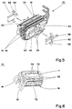
- la figure 5 est une vue similaire de la figure 2, montrant la phase d'enlèvement des volets brisables;
- la figure 6 est une vue similaire de la figure 2 après enlèvement des volets;
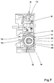
- la figure 7 représente une vue en coupe transversale du bloc déclencheur différentiel après mise en place du transformateur;
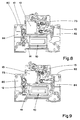
- les figures 8 et 9 sont deux coupes longitudinales de la figure 7 avec bornes de neutre à gauche ou à droite.
- Figure 1 is an exploded perspective view of the zero sequence transformer without the primary and secondary windings.
- Figure 2 shows a perspective view of the transformer in the assembled position after winding of the windings;
- Figures 3 and 4 are side views of Figure 2;
- Figure 5 is a similar view to Figure 2, showing the phase of removal of breakable flaps;
- Figure 6 is a similar view of Figure 2 after removal of the flaps;
- Figure 7 shows a cross-sectional view of the differential trip unit after installation of the transformer;
- Figures 8 and 9 are two longitudinal sections of Figure 7 with neutral terminals on the left or right.
Sur les figures, est représenté un transformateur homopolaire 10 ayant un circuit magnétique 11, sur lequel sont bobinés des enroulements primaires 12,14 de phase et de neutre, et un enroulement secondaire de mesure (non représenté) connecté électriquement à un relais 13 de commande d'un mécanisme 15 de déclenchement. Un tel transformateur homopolaire 10 peut être utilisé dans un interrupteur différentiel, ou dans un bloc déclencheur différentiel 16, (fig. 7) adaptable à un bloc disjoncteur. Le mécanisme 15 est du type décrit dans le document FR-A 2.628.262.In the figures is shown a zero
Le circuit magnétique 11 du transformateur homopolaire 10 présente une forme cylindrique, obtenu soit par enroulement d'une tôle ferromagnétique, soit par frittage d'un matériau pulvérulent à base de ferrite. Le circuit magnétique 11 est entouré par une enveloppe 18 isolante constituée par l'assemblage de deux demi-coquilles 20,22 de formes conjuguées. Une paire de tampons d'amortissement 24,26 conformés en rondelles en matériau spongieux, notamment à base de mousse, est intercalée entre les faces frontales opposées du circuit magnétique 11 et les fonds respectifs de demi-coquilles 20,22 (fig. 1).The
Chaque demi-coquille 20,22 comporte un espace 28 annulaire, délimité par un fourreau 30 interne tubulaire traversé par les enroulements primaires 12,14, et par une paroi 32 externe garnie par une pluralité de rainures 34 de réception des spires constitutives desdits enroulements 12,14. La paroi 32 externe est constituée par deux secteurs 36,38 circulaires diamétralement opposés, réunis entre eux par une paire de volets 40,42 brisables, susceptible d'obturer deux ouvertures 48,50 semi-rectangulaires délimitées par deux embases 52,54 planes opposées s'étendant parallèlement l'une à l'autre.Each half-
Chaque volet 40,42 vient de moulage avec les demi-coquiles 20,22 et est raccordé à la paroi 32 par une liaison mécanique 56 cassable, comprenant une languette à section rétrécie aux points de fixation. La partie centrale de la liaison 56 est équipée d'un bec 58 de retenue et d'un rebord 60 d'accrochage adjacent.Each
La face frontale d'aboutement de la première demi-coquille 20 comporte des pions 62 de détrompage au niveau du secteur 36, et des orifices 64 de positionnement au niveau du secteur 38. Réciproquement, la face frontale d'aboutement de la deuxième demi-coquille 22 est dotée de pions 62 de détrompage sur le secteur 38, et d'orifices 64 sur le secteur 36.The end face of the abutment of the first half-
Le montage et la mise en oeuvre du transformateur homopolaire 10 s'effectuent de la manière suivante :The mounting and implementation of the zero
Sur la figure 1, le rapprochement des deux demi-coquilles 20,22 le long de la direction axiale xx′ provoque l'insertion du circuit magnétique 11 dans les espaces annulaires 28 coaxiaux de l'enveloppe 18.In FIG. 1, the bringing together of the two half-
L'aboutement des deux demi-coquilles 20,22 est autorisé après introduction des pions 62 de détrompage dans les orifices 64 conjugés. L'assemblage final de l'enveloppe 18 est réalisé par encliquetage des quatre becs 58 sur les rebords 60 d'accrochage correspondants. La présence des volets 40,42 ferme totalement l'enveloppe 18 isolante et assure une protection efficace du circuit magnétique 11 durant le transport, la manutention, et la phase de bobinage des enroulements primaires 12,14. Les volets 40,42 jouent également le rôle de conformateurs de l'enveloppe 18, évitant de ce fait les déformations de post-moulage.The abutment of the two half-
Après bobinage des enroulements primaires 12,14 sur l'enveloppe 18 (fig. 2 à 4), il suffit de casser les liaisons 56 des quatres volets 40,42 (fig. 5), de manière à faire apparaître deux fenêtres 70,72 rectangulaires provenant de l'aboutement des ouvertures 48,50 conjugées (fig.6). La distance d (fig.3) entre les embases 52,54 des deux fenêtres 70,72 opposées correspond sensiblement au diamètre extérieur du circuit magnétique 11. L'encliquetage disparaît, mais les enroulements primaires 12,14 assurent le maintien des deux coquilles 20,22 en position rapprochée.After winding of the
Le transformateur homopolaire 10 selon la figure 6 peut ensuite être logé dans le boîtier 73 du bloc déclencheur différentiel 16 (fig. 7 à 9). Les fenêtres 70,72 permettent d'adapter le diamètre du circuit magnétique 11 à l'espace entre les deux parois 74,76, malgré que le diamètre de la paroi 32 externe de l'enveloppe 18 soit supérieur à la largeur du bloc déclencheur 16. La présence des deux fenêtres 70,72 permet de loger le transformateur 10 dans un boîtier 73 standard de 18 mm.The zero
Le circuit magnétique 11 peut également présenter une forme torique.The
On remarque la disposition longitudinale du transformateur 10 homopolaire s'étendant dans la zone centrale du boîtier 73 selon une direction parallèle aux grandes parois 74,76 latérales. Le boîtier 73 présente des alvéoles 80,82 autorisant la présence de bornes de neutre 84 à gauche (fig. 8) ou à droite (fig.9) selon le type d'installation électrique.Note the longitudinal arrangement of the zero
Claims (8)
- A homopolar transformer for a differential switch or circuit breaker, comprising a magnetic circuit (11) of cylindrical or toroidal shape, housed in an enclosure (18) made of moulded insulating material formed by end-to-end assembly of two conjugate half-shells (20, 22), and phase and neutral primary windings (12, 14) wound onto the enclosure (18), each half-shell (20, 22) of which encloses an annular space (28) bounded by a tubular internal sheath (30) through which said windings pass, characterized in that the external wall (32) of each half-shell (20, 22) comprises first and second breakable flaps (40, 42), designed to be in an unbroken state enabling the abutted half-shells (20, 22) to be automatically clipped together, and in a broken state making two diametrically opposite windows (70, 72) appear in the enclosure (18), the distance d between the windows (70, 72) corresponding appreciably to the external diameter of the magnetic circuit (11).
- The homopolar transformer according to claim 1, characterized in that the wall of each half-shell (20, 22) is equipped with a first and a second diametrically opposite circular sector (36, 38) joined together by said breakable flaps (40, 42), each flap being joined to the wall (32) by a breakable mechanical link (56) cast with the corresponding half-shell (20, 22).
- The homopolar transformer according to claim 2, characterized in that the mechanical link (56) of each flap (40, 42) is equipped with a retaining nose (58) and an adjacent latching edge (60), enabling automatic clipping together of the two half-shells (20, 22).
- The homopolar transformer according to claim 2 or 3, characterized in that the front abutment face of one of the half-shells (20) is provided with error prevention pins on the first sector (36), and positioning orifices (64) on the second sector (38), and that the conjugate front face of the other half-shell (22) comprises error prevention pins on the second sector (38), and positioning orifices (64) on the second sector (36).
- The homopolar transformer according to one of the claims 1 to 4, characterized in that a damping pad (24, 26) is inserted between the magnetic circuit (11) and the base of each half-shell (20, 22).
- The homopolar transformer according to one of the claims 2 to 5, characterized in that the cylindrical lateral surface of the insulating enclosure (18) comprises a plurality of grooves (34) receiving the primary windings (12, 14).
- The assembly process of a case of a homopolar transformer according to one of the claims 1 to 6, characterized in that removal of the flaps (40, 42) is performed after the primary windings (12, 14) have been wound onto the enclosure (18), and just before the transformer (10) is fitted in the case (73), the appearance of the windows (70, 72) enabling the magnetic circuit (11) to be positioned longitudinally in the space between two large parallel walls (74, 76) of the case (73).
- The assembly process according to claim 7, characterized in that the bases (52, 54) bounding the two windows (70, 72) of the enclosure (18) come into engagement against the two walls (74, 76) to perform wedging of the transformer (10) in the centre zone of the case (73).
Applications Claiming Priority (2)
| Application Number | Priority Date | Filing Date | Title |
|---|---|---|---|
| FR9006549 | 1990-05-10 | ||
| FR9006549A FR2662014B1 (en) | 1990-05-10 | 1990-05-10 | HOMOPOLAR TRANSFORMER FOR DIFFERENTIAL SWITCHES OR CIRCUIT BREAKERS AND MOUNTING METHOD. |
Publications (2)
| Publication Number | Publication Date |
|---|---|
| EP0456583A1 EP0456583A1 (en) | 1991-11-13 |
| EP0456583B1 true EP0456583B1 (en) | 1994-06-22 |
Family
ID=9396960
Family Applications (1)
| Application Number | Title | Priority Date | Filing Date |
|---|---|---|---|
| EP91420129A Expired - Lifetime EP0456583B1 (en) | 1990-05-10 | 1991-04-19 | Homopolar transformer for differential switches or circuit breakers, and mounting method |
Country Status (6)
| Country | Link |
|---|---|
| EP (1) | EP0456583B1 (en) |
| AT (1) | ATE107796T1 (en) |
| DE (1) | DE69102583T2 (en) |
| ES (1) | ES2059092T3 (en) |
| FR (1) | FR2662014B1 (en) |
| PT (1) | PT97625B (en) |
Families Citing this family (8)
| Publication number | Priority date | Publication date | Assignee | Title |
|---|---|---|---|---|
| FR2711838B1 (en) * | 1993-10-25 | 1996-01-05 | Legrand Sa | Toroid housing, and wound toroid comprising such a housing. |
| DE10013143C2 (en) * | 2000-03-17 | 2002-06-27 | Aeg Niederspannungstech Gmbh | transducers |
| ITBG20030034A1 (en) * | 2003-05-20 | 2004-11-21 | Abb Service Srl | DEVICE FOR CONTAINING HALF CURRENT SENSORS. |
| AT505096B1 (en) * | 2004-10-25 | 2012-01-15 | Moeller Gebaeudeautomation Kg | SWITCHING DEVICE |
| DE102012203337B4 (en) | 2012-03-02 | 2020-04-23 | Siemens Aktiengesellschaft | Total current transformer and electrical protection switching device |
| CN107545987B (en) * | 2017-08-08 | 2019-04-26 | 芜湖市凯鑫避雷器有限责任公司 | A kind of inside transformer positioning mechanism |
| DE102019213152A1 (en) * | 2019-08-30 | 2021-03-04 | Siemens Aktiengesellschaft | Rogowski transformer |
| DE102021208514A1 (en) | 2021-08-05 | 2023-02-09 | Siemens Aktiengesellschaft | Draw-in summation current transformers, residual current circuit breakers and assembly methods |
Family Cites Families (4)
| Publication number | Priority date | Publication date | Assignee | Title |
|---|---|---|---|---|
| DE1047297B (en) * | 1956-05-02 | 1958-12-24 | Gen Electric | Winding head support on the rotor for a rotary transformer |
| FR2147816B1 (en) * | 1971-07-30 | 1975-02-07 | Landis & Gyr Ag | |
| DE2310201A1 (en) * | 1973-03-01 | 1974-09-05 | Licentia Gmbh | COIL FOR TRANSFORMERS OR REACTORS WITH CUTTING TAPE CORE |
| US4716394A (en) * | 1987-03-12 | 1987-12-29 | Cosmo Plastics Company | Bobbin device |
-
1990
- 1990-05-10 FR FR9006549A patent/FR2662014B1/en not_active Expired - Lifetime
-
1991
- 1991-04-19 ES ES91420129T patent/ES2059092T3/en not_active Expired - Lifetime
- 1991-04-19 EP EP91420129A patent/EP0456583B1/en not_active Expired - Lifetime
- 1991-04-19 DE DE69102583T patent/DE69102583T2/en not_active Expired - Fee Related
- 1991-04-19 AT AT91420129T patent/ATE107796T1/en not_active IP Right Cessation
- 1991-05-09 PT PT97625A patent/PT97625B/en not_active IP Right Cessation
Also Published As
| Publication number | Publication date |
|---|---|
| EP0456583A1 (en) | 1991-11-13 |
| DE69102583T2 (en) | 1994-12-15 |
| DE69102583D1 (en) | 1994-07-28 |
| ATE107796T1 (en) | 1994-07-15 |
| ES2059092T3 (en) | 1994-11-01 |
| PT97625B (en) | 1998-11-30 |
| PT97625A (en) | 1993-06-30 |
| FR2662014A1 (en) | 1991-11-15 |
| FR2662014B1 (en) | 1992-07-24 |
Similar Documents
| Publication | Publication Date | Title |
|---|---|---|
| EP0456583B1 (en) | Homopolar transformer for differential switches or circuit breakers, and mounting method | |
| EP0337900B1 (en) | High sensitivity electromagnetic tripper | |
| EP0187055B1 (en) | Polarised electromagnetic relay with magnetic latching for a trip device of a circuit breaker | |
| EP0375568B1 (en) | Modulator assembly device for a multipole differential circuit breaker | |
| FR2715517A1 (en) | Differential trip unit. | |
| EP0320411A1 (en) | Ground fault circuit interrupter | |
| US5994979A (en) | Magnetic core noise filter with an integrally formed outer sheath and inner insulator | |
| Baralis et al. | Full-wave design of broad-band compact waveguide step-twists | |
| EP0395512A1 (en) | Ignition coil, particularly for internal combustion engines for motor vehicles, and means for securing the primary and secondary assemblies | |
| EP0509936A2 (en) | Homopolar transformer with magnetic circuit insensitive to mechanical stresses, and manufacturing method | |
| EP3159906B1 (en) | Electrical switching apparatus including a switching mechanism and at least one auxiliary module | |
| FR2700395A1 (en) | Transformer, in particular measuring transformer, for example for the detection of faults on electric cables. | |
| EP1117115B1 (en) | Differential electric protection device, in particular a differential switch | |
| EP0099786B1 (en) | Two-phase differential circuit breaker | |
| JP2003178910A (en) | Coil device | |
| EP0072266B1 (en) | Method of obtaining a coil with a closed magnetic circuit and a permanent magnet for the ignition of combustion engines | |
| EP0456586B1 (en) | Test circuit for a differential tripping device | |
| FR2811805A1 (en) | Electrical differential protection circuit switch reinforcing isolation mechanism having primary conductors rotating section attached and freeing conductor ends apparatus connection. | |
| EP0558428A1 (en) | Toroidal transformer for class A differential sensor | |
| US6788177B1 (en) | Commonized actuator for normally open and normally closed modes | |
| EP0326772B1 (en) | Releasing relay with spitting remote sensing-element | |
| JPH01253138A (en) | Coil for electromagnetic relay with delayed response | |
| EP0354121B1 (en) | Electromagnetic power coil | |
| EP0130914B1 (en) | Electrical switch, particularly for motor cars, provided with electrical latching bobbins | |
| US5622326A (en) | Dustproofing rib structure of tape cassette with lid |
Legal Events
| Date | Code | Title | Description |
|---|---|---|---|
| PUAI | Public reference made under article 153(3) epc to a published international application that has entered the european phase |
Free format text: ORIGINAL CODE: 0009012 |
|
| AK | Designated contracting states |
Kind code of ref document: A1 Designated state(s): AT BE DE ES GB IT |
|
| 17P | Request for examination filed |
Effective date: 19920513 |
|
| 17Q | First examination report despatched |
Effective date: 19930820 |
|
| GRAA | (expected) grant |
Free format text: ORIGINAL CODE: 0009210 |
|
| AK | Designated contracting states |
Kind code of ref document: B1 Designated state(s): AT BE DE ES GB IT |
|
| REF | Corresponds to: |
Ref document number: 107796 Country of ref document: AT Date of ref document: 19940715 Kind code of ref document: T |
|
| REF | Corresponds to: |
Ref document number: 69102583 Country of ref document: DE Date of ref document: 19940728 |
|
| ITF | It: translation for a ep patent filed | ||
| GBT | Gb: translation of ep patent filed (gb section 77(6)(a)/1977) |
Effective date: 19940818 |
|
| REG | Reference to a national code |
Ref country code: ES Ref legal event code: FG2A Ref document number: 2059092 Country of ref document: ES Kind code of ref document: T3 |
|
| PG25 | Lapsed in a contracting state [announced via postgrant information from national office to epo] |
Ref country code: ES Free format text: LAPSE BECAUSE OF NON-PAYMENT OF DUE FEES Effective date: 19950420 |
|
| PLBE | No opposition filed within time limit |
Free format text: ORIGINAL CODE: 0009261 |
|
| STAA | Information on the status of an ep patent application or granted ep patent |
Free format text: STATUS: NO OPPOSITION FILED WITHIN TIME LIMIT |
|
| 26N | No opposition filed | ||
| PGFP | Annual fee paid to national office [announced via postgrant information from national office to epo] |
Ref country code: DE Payment date: 19990412 Year of fee payment: 9 |
|
| REG | Reference to a national code |
Ref country code: ES Ref legal event code: FD2A Effective date: 19990503 |
|
| PGFP | Annual fee paid to national office [announced via postgrant information from national office to epo] |
Ref country code: AT Payment date: 20000412 Year of fee payment: 10 |
|
| PGFP | Annual fee paid to national office [announced via postgrant information from national office to epo] |
Ref country code: GB Payment date: 20000419 Year of fee payment: 10 |
|
| PGFP | Annual fee paid to national office [announced via postgrant information from national office to epo] |
Ref country code: BE Payment date: 20000622 Year of fee payment: 10 |
|
| PG25 | Lapsed in a contracting state [announced via postgrant information from national office to epo] |
Ref country code: DE Free format text: LAPSE BECAUSE OF NON-PAYMENT OF DUE FEES Effective date: 20010201 |
|
| PG25 | Lapsed in a contracting state [announced via postgrant information from national office to epo] |
Ref country code: GB Free format text: LAPSE BECAUSE OF NON-PAYMENT OF DUE FEES Effective date: 20010419 Ref country code: AT Free format text: LAPSE BECAUSE OF NON-PAYMENT OF DUE FEES Effective date: 20010419 |
|
| PG25 | Lapsed in a contracting state [announced via postgrant information from national office to epo] |
Ref country code: BE Free format text: LAPSE BECAUSE OF NON-PAYMENT OF DUE FEES Effective date: 20010430 |
|
| BERE | Be: lapsed |
Owner name: MERLIN GERIN Effective date: 20010430 |
|
| GBPC | Gb: european patent ceased through non-payment of renewal fee |
Effective date: 20010419 |
|
| PG25 | Lapsed in a contracting state [announced via postgrant information from national office to epo] |
Ref country code: IT Free format text: LAPSE BECAUSE OF NON-PAYMENT OF DUE FEES;WARNING: LAPSES OF ITALIAN PATENTS WITH EFFECTIVE DATE BEFORE 2007 MAY HAVE OCCURRED AT ANY TIME BEFORE 2007. THE CORRECT EFFECTIVE DATE MAY BE DIFFERENT FROM THE ONE RECORDED. Effective date: 20050419 |