EP0456586A1 - Testschaltung für einen Differentialauslöser - Google Patents
Testschaltung für einen Differentialauslöser Download PDFInfo
- Publication number
- EP0456586A1 EP0456586A1 EP91420141A EP91420141A EP0456586A1 EP 0456586 A1 EP0456586 A1 EP 0456586A1 EP 91420141 A EP91420141 A EP 91420141A EP 91420141 A EP91420141 A EP 91420141A EP 0456586 A1 EP0456586 A1 EP 0456586A1
- Authority
- EP
- European Patent Office
- Prior art keywords
- test
- switch
- strands
- strand
- circuit
- Prior art date
- Legal status (The legal status is an assumption and is not a legal conclusion. Google has not performed a legal analysis and makes no representation as to the accuracy of the status listed.)
- Granted
Links
- 238000004804 winding Methods 0.000 claims abstract description 18
- 230000007246 mechanism Effects 0.000 claims abstract description 14
- 230000001681 protective effect Effects 0.000 claims abstract description 10
- 230000005540 biological transmission Effects 0.000 claims abstract description 7
- 230000007935 neutral effect Effects 0.000 claims description 11
- 239000004020 conductor Substances 0.000 claims description 7
- 241000549194 Euonymus europaeus Species 0.000 abstract 1
- 238000004519 manufacturing process Methods 0.000 description 3
- 230000000994 depressogenic effect Effects 0.000 description 2
- 238000003780 insertion Methods 0.000 description 2
- 230000037431 insertion Effects 0.000 description 2
- 239000002184 metal Substances 0.000 description 2
- 238000006243 chemical reaction Methods 0.000 description 1
- 238000006073 displacement reaction Methods 0.000 description 1
- 230000000694 effects Effects 0.000 description 1
- 238000002955 isolation Methods 0.000 description 1
- 238000005259 measurement Methods 0.000 description 1
- 230000002035 prolonged effect Effects 0.000 description 1
- 238000000926 separation method Methods 0.000 description 1
Images

Classifications
-
- H—ELECTRICITY
- H01—ELECTRIC ELEMENTS
- H01H—ELECTRIC SWITCHES; RELAYS; SELECTORS; EMERGENCY PROTECTIVE DEVICES
- H01H83/00—Protective switches, e.g. circuit-breaking switches, or protective relays operated by abnormal electrical conditions otherwise than solely by excess current
- H01H83/02—Protective switches, e.g. circuit-breaking switches, or protective relays operated by abnormal electrical conditions otherwise than solely by excess current operated by earth fault currents
- H01H83/04—Protective switches, e.g. circuit-breaking switches, or protective relays operated by abnormal electrical conditions otherwise than solely by excess current operated by earth fault currents with testing means for indicating the ability of the switch or relay to function properly
- H01H2083/045—Auxiliary switch opening testing circuit in synchronism with the main circuit
Definitions
- Document FR-A-2,489,587 discloses a test circuit in which each of the conductive strands of the test switch and of the protective switch belongs to a separate spring. This results in a positioning of the two springs on two offset axes, with cooperation of the two strands either with the opposite terminals of the resistor, or with a metal finger.
- the two springs are at different potentials, which imposes an appropriate isolation distance between the two springs, to the detriment of the bulk.
- the two springs are at the same potential of the phase circuit, but the presence of the metal finger for placing the two switches in series complicates the mounting of the test circuit in the circuit breaker.
- the object of the invention is to simplify the production of a test circuit for a differential trip device.
- the test circuit according to the invention is characterized in that the first and second strands are part of a double spring of conductive material, having two helical windings mounted coaxially on a common axis, and connected to each other by a intermediate link bearing on a fixed support of the housing.
- Each winding of the double spring has a predetermined number of turns to define the elasticity and the specific restoring force of the corresponding strand.
- the two strands of the spring extend in the same direction, and parallel to each other in a direction perpendicular to the axis, the interval between the two juxtaposed strands corresponding to the total length of the two windings taken along of the axis.
- the elasticity of the double spring biases the first and second strands in the same pivoting direction, to ensure respectively the recall of the test button after opening the test switch, and the opening of the protective switch after differential triggering .
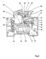
- a single-pole neutral neutral circuit breaker 10 passing through is housed in an insulating box 12 subdivided by a wall 14 for separation into two juxtaposed compartments.
- the interior of the first compartment 16 is visible in FIG. 2, and includes a differential protection device 18 and the neutral circuit 20 passing, the latter being connected to a pair of terminals 22,24 for input and output of neutral. .
- the second compartment serves as a housing for the phase circuit 26 comprising a pair of phase contacts 28, 30, a first control mechanism 32 piloted by a magnetothermic trip unit with bimetallic strip 34 and coil 36, and a pair of terminals 38.40 d 'phase input and output.
- the first mechanism 32 can be of the type described in document FR-A-2,616,583.
- the differential protection device 18 comprises a differential transformer 42 with a toroid 44 having primary phase 44 and neutral windings 46, a measurement winding (not shown) connected to a trigger relay 48, and a second trigger mechanism 50 controlled by the relay 48 and a lever 52.
- the second mechanism can be of the type described in the document FR-A-2,628,262.
- the two mechanisms 32.50 are interconnected by mechanical links, authorizing an automatic tripping function of the first mechanism 32 when a differential tripping order is issued by the relay 48, and an automatic resetting function of the relay 48 by the first mechanism 32 after the differential triggering operation.
- a test circuit 54 makes it possible to simulate a joint leakage current to cause a trip differential forced by relay 48.
- test button 56 intended to insert a test resistance 58 between two points 59,61 of different potentials of phase circuit 26 and neutral circuit 20.
- This insertion of resistance 58 s operates by means of a test switch 60 actuated by the test button 56, and a protection switch 62 associated with a pivoting transmission part 64 pivotally mounted on an axis 65 of the second mechanism 50.
- the test circuit 54 is equipped with a double spring 66 made of conductive material, having two helical windings 68, 70 mounted coaxially on a common axis 71 secured to the wall 14 of the insulating housing 12.
- the winding 68 is extended by a first elastic strand 72 of the test switch 60, while the winding 70 has a second elastic strand 74 of the protective switch 62.
- the two strands 72,74 extend substantially parallel to each other on the same side of the axis 71, and in a direction perpendicular to the axis 71.
- connection 76 common intermediate in the form of a half-loop bearing on a fixed support 78 of the housing 12 at a point situated on the same side of the strands 72, 74 relative to the axis 71.
- the elasticity of the first strand 72 of the spring 66 urges the test button 56 towards the rest position, causing the opening of the test switch 60 (solid lines in FIG. 1). Pressing the test button 56 in the direction of the arrow F1 in FIG. 2, directly drives the first strand 72 towards the test position (in dotted lines) to come into contact with a terminal of the resistor 58.
- the switch d test 60 remains permanently closed in the depressed position of test button 56.
- the other terminal of the resistor is permanently connected to point 61 of neutral circuit 20.
- the transmission part 64 cooperates with the second strand 74 of the spring 66 to keep the protective switch 62 closed (in solid lines in FIG. 1). In this position, the end of the second strand 74 is supported on an electrode 80 connected to point 59 of the phase circuit by a connecting conductor 82.
- the circuit breaker 10 opens, and the transmission part 64 pivots around the axis 65 in the counterclockwise direction (arrow F2 in FIG. 1) to allow the displacement of the second strand 74 towards the dotted position, corresponding to the opening of the protective switch 62.
- the two elementary strands 72,74 of the conductive spring 66 constitute the respective movable contacts of the switches 60,62 of the test circuit 54, the elasticity of each strand 72,74 being a function of the number of turns of the winding 68, 70 correspondent.
- the first strand 72 is shaped into test contact of the switch d 'test 60, and as a return member of the test button 56 to the rest position.
- the second strand 74 is arranged in self-interrupting contact of the protective switch 62, authorizing the automatic interruption of the test circuit 54 after differential tripping, even if the test switch 60 remains closed during prolonged holding of the button test 56 in the depressed position.
- the elasticity of the spring 66 urges the two elementary strands 72, 74 in the same direction of pivoting thanks to the reaction of the intermediate link 76 on the fixed support 78.
- the windings 68.70 can have a different number of turns depending on the requirement of the specific restoring forces of the strands 72.74.
- test switch 60 When the circuit breaker 10 is tripped, the test switch 60 is open, and the protection switch closed. Test circuit 54 is permanently interrupted, and no current flows in resistor 58 and in spring 66. The two windings 68, 70 of the latter are found at the potential of point 59 associated with the phase circuit.
- test button 56 To carry out a differential test, simply press the test button 56 in the direction of the arrow F1, which closes the test switch 60, and activates the test circuit 54 by the potential difference present between the points 59 and 61.
- the leakage current passing through the resistor 58 is detected by the toroid 44, causing a differential trip by the relay 48.
- the test circuit 54 is then interrupted by automatic opening of the protection switch 62.
- the release of the test button 56 causes it to return to the rest position under the elastic effect of the first strand 72.
- the second mechanism 50 is reset by pivoting the lever 52 to the right (FIG. 2) causing the protective switch 62 to close again.
- test circuit 54 is also applicable to a modular differential circuit breaker with neutral cut, and to a one-piece differential switch. In the latter case, the relay of the differential protection device acts directly on the switch control mechanism.
Landscapes
- Breakers (AREA)
- Polysaccharides And Polysaccharide Derivatives (AREA)
- Emergency Protection Circuit Devices (AREA)
- Investigating Or Analysing Biological Materials (AREA)
Applications Claiming Priority (2)
| Application Number | Priority Date | Filing Date | Title |
|---|---|---|---|
| FR9006550 | 1990-05-10 | ||
| FR9006550A FR2662019B1 (fr) | 1990-05-10 | 1990-05-10 | Circuit test pour un declencheur differentiel. |
Publications (2)
| Publication Number | Publication Date |
|---|---|
| EP0456586A1 true EP0456586A1 (de) | 1991-11-13 |
| EP0456586B1 EP0456586B1 (de) | 1994-10-19 |
Family
ID=9396962
Family Applications (1)
| Application Number | Title | Priority Date | Filing Date |
|---|---|---|---|
| EP91420141A Expired - Lifetime EP0456586B1 (de) | 1990-05-10 | 1991-04-29 | Testschaltung für einen Differentialauslöser |
Country Status (5)
| Country | Link |
|---|---|
| EP (1) | EP0456586B1 (de) |
| AT (1) | ATE113140T1 (de) |
| DE (1) | DE69104647T2 (de) |
| ES (1) | ES2065654T3 (de) |
| FR (1) | FR2662019B1 (de) |
Cited By (1)
| Publication number | Priority date | Publication date | Assignee | Title |
|---|---|---|---|---|
| EP1562212A3 (de) * | 2004-02-06 | 2006-06-21 | Siemens Aktiengesellschaft | Fehlerstromschutzschaltvorrichtung |
Citations (4)
| Publication number | Priority date | Publication date | Assignee | Title |
|---|---|---|---|---|
| FR2489587A1 (fr) * | 1980-08-30 | 1982-03-05 | Licentia Gmbh | Disjoncteur de courant de fuite comportant un interrupteur a touche pour inserer une resistance dans un circuit de courant d'essai |
| EP0200581A1 (de) * | 1985-03-08 | 1986-11-05 | Electrotecnica F. De Roda, S.A. | Fehlerstromschutzschaltermechanismen die ihre Kupplung in oder an Selbstausschaltern erlauben |
| EP0231732A2 (de) * | 1985-12-02 | 1987-08-12 | Felten & Guilleaume Fabrik elektrischer Apparate Aktiengesellschaft | Fehlerstrom- und Leitungsschutzschalter |
| EP0320929A2 (de) * | 1987-12-17 | 1989-06-21 | ABB Elettrocondutture S.p.A. | Vorrichtung zur Auslösung der Kontakte von Diffenrentialschaltern |
-
1990
- 1990-05-10 FR FR9006550A patent/FR2662019B1/fr not_active Expired - Fee Related
-
1991
- 1991-04-29 ES ES91420141T patent/ES2065654T3/es not_active Expired - Lifetime
- 1991-04-29 DE DE69104647T patent/DE69104647T2/de not_active Expired - Fee Related
- 1991-04-29 AT AT91420141T patent/ATE113140T1/de not_active IP Right Cessation
- 1991-04-29 EP EP91420141A patent/EP0456586B1/de not_active Expired - Lifetime
Patent Citations (4)
| Publication number | Priority date | Publication date | Assignee | Title |
|---|---|---|---|---|
| FR2489587A1 (fr) * | 1980-08-30 | 1982-03-05 | Licentia Gmbh | Disjoncteur de courant de fuite comportant un interrupteur a touche pour inserer une resistance dans un circuit de courant d'essai |
| EP0200581A1 (de) * | 1985-03-08 | 1986-11-05 | Electrotecnica F. De Roda, S.A. | Fehlerstromschutzschaltermechanismen die ihre Kupplung in oder an Selbstausschaltern erlauben |
| EP0231732A2 (de) * | 1985-12-02 | 1987-08-12 | Felten & Guilleaume Fabrik elektrischer Apparate Aktiengesellschaft | Fehlerstrom- und Leitungsschutzschalter |
| EP0320929A2 (de) * | 1987-12-17 | 1989-06-21 | ABB Elettrocondutture S.p.A. | Vorrichtung zur Auslösung der Kontakte von Diffenrentialschaltern |
Cited By (1)
| Publication number | Priority date | Publication date | Assignee | Title |
|---|---|---|---|---|
| EP1562212A3 (de) * | 2004-02-06 | 2006-06-21 | Siemens Aktiengesellschaft | Fehlerstromschutzschaltvorrichtung |
Also Published As
| Publication number | Publication date |
|---|---|
| ATE113140T1 (de) | 1994-11-15 |
| ES2065654T3 (es) | 1995-02-16 |
| EP0456586B1 (de) | 1994-10-19 |
| DE69104647T2 (de) | 1995-05-11 |
| FR2662019B1 (fr) | 1992-07-24 |
| FR2662019A1 (fr) | 1991-11-15 |
| DE69104647D1 (de) | 1994-11-24 |
Similar Documents
| Publication | Publication Date | Title |
|---|---|---|
| EP0264314B1 (de) | Mehrpoliger Differentialmodulschutzschalter | |
| EP0665569B1 (de) | Differential Auslöseeinheit | |
| EP0331586B1 (de) | Betätigungsmechanismus eines Hilfsauslöseblocks für Modulschutzschalter | |
| EP0264313B1 (de) | Elektrischer Differentialschutzapparat mit Testschaltung | |
| EP0371887B1 (de) | Modulschützschalter mit Hilfsauslöseblock mit einer automatischen oder unabhängigen Wiedereinschaltung | |
| FR2779568A1 (fr) | Dispositif de coupure electrique comprenant un dispositif de declenchement differentiel et disjoncteur comprenant un tel dispositif | |
| EP0199612B1 (de) | Mehrpoliges Schaltgerät mit Fernsteuerung | |
| EP0557214B1 (de) | Einpol- und Nulleiterdifferentialschutzschalter mit Prüfkreis | |
| US6229414B1 (en) | Make-and-break mechanism for circuit breaker | |
| CA1077550A (en) | Circuit breaker with improved latch mechanism | |
| EP0456586B1 (de) | Testschaltung für einen Differentialauslöser | |
| CH686853A5 (fr) | Appareil interrupteur de protection accouplable à un module de commande et/ou à un module de signalisation. | |
| EP0275750B1 (de) | Zweipoliger Differentialunterbrecher mit Fehleranzeige | |
| EP0378030A1 (de) | Unverletzliche Regelungsvorrichtung eines elektrischen Gerätes | |
| EP2743958B1 (de) | Elektrisches Stromschaltgerät, insbesondere Abzweigschalter | |
| EP0639845B1 (de) | Vierpoliger Differentialschutzschalter | |
| WO2019122539A1 (fr) | Appareil électrique de commutation de type modulaire | |
| EP0665623A1 (de) | Prüfeinrichtung für Differentialschutzschalter und diese Vorrichtung enthaltende Differentialschutzschalter | |
| EP2743959B1 (de) | Thermische Auslösvorrichtung und Schutzschalter mit dieser Vorrichtung | |
| EP0045672B1 (de) | Kleinschalter mit Abschaltung des Nulleiters und des Phasenleiters | |
| FR2620265A1 (fr) | Ensemble magnetique de declenchement pour disjoncteur | |
| EP0649156B1 (de) | Schutzeinrichtung dargestellt durch die Reihenschaltung eines Schutzschalters mit einem Schaltgerät | |
| FR2723469A1 (fr) | Dispositif de declenchement magnetique pour disjoncteur et disjoncteur muni d'un tel dispositif | |
| FR2486304A1 (fr) | Interrupteur magneto-thermique differentiel | |
| FR2553928A1 (fr) | Bilame a chauffage mixte pour declencheur thermique d'un appareil de coupure |
Legal Events
| Date | Code | Title | Description |
|---|---|---|---|
| PUAI | Public reference made under article 153(3) epc to a published international application that has entered the european phase |
Free format text: ORIGINAL CODE: 0009012 |
|
| AK | Designated contracting states |
Kind code of ref document: A1 Designated state(s): AT DE ES GB IT |
|
| 17P | Request for examination filed |
Effective date: 19920513 |
|
| 17Q | First examination report despatched |
Effective date: 19940118 |
|
| GRAA | (expected) grant |
Free format text: ORIGINAL CODE: 0009210 |
|
| AK | Designated contracting states |
Kind code of ref document: B1 Designated state(s): AT DE ES GB IT |
|
| REF | Corresponds to: |
Ref document number: 113140 Country of ref document: AT Date of ref document: 19941115 Kind code of ref document: T |
|
| REF | Corresponds to: |
Ref document number: 69104647 Country of ref document: DE Date of ref document: 19941124 |
|
| ITF | It: translation for a ep patent filed | ||
| GBT | Gb: translation of ep patent filed (gb section 77(6)(a)/1977) |
Effective date: 19950112 |
|
| REG | Reference to a national code |
Ref country code: ES Ref legal event code: FG2A Ref document number: 2065654 Country of ref document: ES Kind code of ref document: T3 |
|
| PLBE | No opposition filed within time limit |
Free format text: ORIGINAL CODE: 0009261 |
|
| STAA | Information on the status of an ep patent application or granted ep patent |
Free format text: STATUS: NO OPPOSITION FILED WITHIN TIME LIMIT |
|
| 26N | No opposition filed | ||
| PGFP | Annual fee paid to national office [announced via postgrant information from national office to epo] |
Ref country code: DE Payment date: 20010411 Year of fee payment: 11 Ref country code: AT Payment date: 20010411 Year of fee payment: 11 |
|
| PGFP | Annual fee paid to national office [announced via postgrant information from national office to epo] |
Ref country code: GB Payment date: 20010425 Year of fee payment: 11 |
|
| PGFP | Annual fee paid to national office [announced via postgrant information from national office to epo] |
Ref country code: ES Payment date: 20010430 Year of fee payment: 11 |
|
| REG | Reference to a national code |
Ref country code: GB Ref legal event code: IF02 |
|
| PG25 | Lapsed in a contracting state [announced via postgrant information from national office to epo] |
Ref country code: GB Free format text: LAPSE BECAUSE OF NON-PAYMENT OF DUE FEES Effective date: 20020429 Ref country code: AT Free format text: LAPSE BECAUSE OF NON-PAYMENT OF DUE FEES Effective date: 20020429 |
|
| PG25 | Lapsed in a contracting state [announced via postgrant information from national office to epo] |
Ref country code: ES Free format text: LAPSE BECAUSE OF NON-PAYMENT OF DUE FEES Effective date: 20020430 |
|
| PG25 | Lapsed in a contracting state [announced via postgrant information from national office to epo] |
Ref country code: DE Free format text: LAPSE BECAUSE OF NON-PAYMENT OF DUE FEES Effective date: 20021101 |
|
| GBPC | Gb: european patent ceased through non-payment of renewal fee |
Effective date: 20020429 |
|
| REG | Reference to a national code |
Ref country code: ES Ref legal event code: FD2A Effective date: 20030514 |
|
| PG25 | Lapsed in a contracting state [announced via postgrant information from national office to epo] |
Ref country code: IT Free format text: LAPSE BECAUSE OF NON-PAYMENT OF DUE FEES;WARNING: LAPSES OF ITALIAN PATENTS WITH EFFECTIVE DATE BEFORE 2007 MAY HAVE OCCURRED AT ANY TIME BEFORE 2007. THE CORRECT EFFECTIVE DATE MAY BE DIFFERENT FROM THE ONE RECORDED. Effective date: 20050429 |