EP0456629B1 - Einrichtung zur kontinuierlichen Messung der Dichte und des Gesamtgewichts des Inhaltes des Laderaums eines Laderaumbaggers - Google Patents
Einrichtung zur kontinuierlichen Messung der Dichte und des Gesamtgewichts des Inhaltes des Laderaums eines Laderaumbaggers Download PDFInfo
- Publication number
- EP0456629B1 EP0456629B1 EP91870075A EP91870075A EP0456629B1 EP 0456629 B1 EP0456629 B1 EP 0456629B1 EP 91870075 A EP91870075 A EP 91870075A EP 91870075 A EP91870075 A EP 91870075A EP 0456629 B1 EP0456629 B1 EP 0456629B1
- Authority
- EP
- European Patent Office
- Prior art keywords
- probe
- installation according
- duct
- installation
- carriage
- Prior art date
- Legal status (The legal status is an assumption and is not a legal conclusion. Google has not performed a legal analysis and makes no representation as to the accuracy of the status listed.)
- Expired - Lifetime
Links
- 238000005259 measurement Methods 0.000 title claims description 30
- 239000000463 material Substances 0.000 title claims description 19
- 239000000523 sample Substances 0.000 claims description 82
- 238000009434 installation Methods 0.000 claims description 68
- 230000002285 radioactive effect Effects 0.000 claims description 30
- 230000007246 mechanism Effects 0.000 claims description 26
- 239000002184 metal Substances 0.000 claims description 25
- 230000005540 biological transmission Effects 0.000 claims description 22
- 230000005855 radiation Effects 0.000 claims description 14
- 230000003287 optical effect Effects 0.000 claims description 6
- 230000001105 regulatory effect Effects 0.000 claims description 6
- 229910000831 Steel Inorganic materials 0.000 claims description 4
- 230000003321 amplification Effects 0.000 claims description 4
- 239000003638 chemical reducing agent Substances 0.000 claims description 4
- 239000013078 crystal Substances 0.000 claims description 4
- 238000003199 nucleic acid amplification method Methods 0.000 claims description 4
- 239000010959 steel Substances 0.000 claims description 4
- 238000004458 analytical method Methods 0.000 claims description 3
- 239000000919 ceramic Substances 0.000 claims description 3
- 238000012545 processing Methods 0.000 claims description 3
- 230000000007 visual effect Effects 0.000 claims description 3
- 239000011324 bead Substances 0.000 claims description 2
- 230000001276 controlling effect Effects 0.000 claims description 2
- 239000011344 liquid material Substances 0.000 claims description 2
- 239000011343 solid material Substances 0.000 claims description 2
- 238000004804 winding Methods 0.000 claims description 2
- 239000013049 sediment Substances 0.000 description 13
- 239000000203 mixture Substances 0.000 description 11
- 238000000034 method Methods 0.000 description 7
- 230000006978 adaptation Effects 0.000 description 6
- 239000002245 particle Substances 0.000 description 6
- 238000001739 density measurement Methods 0.000 description 4
- 230000006870 function Effects 0.000 description 4
- 230000001131 transforming effect Effects 0.000 description 4
- 239000012530 fluid Substances 0.000 description 3
- 238000012423 maintenance Methods 0.000 description 3
- 230000002093 peripheral effect Effects 0.000 description 3
- 230000008569 process Effects 0.000 description 3
- 238000010586 diagram Methods 0.000 description 2
- 238000006073 displacement reaction Methods 0.000 description 2
- 238000005538 encapsulation Methods 0.000 description 2
- 235000021183 entrée Nutrition 0.000 description 2
- 230000002706 hydrostatic effect Effects 0.000 description 2
- 230000008439 repair process Effects 0.000 description 2
- 239000007787 solid Substances 0.000 description 2
- XLYOFNOQVPJJNP-UHFFFAOYSA-N water Substances O XLYOFNOQVPJJNP-UHFFFAOYSA-N 0.000 description 2
- 241001080024 Telles Species 0.000 description 1
- 238000010521 absorption reaction Methods 0.000 description 1
- 238000004891 communication Methods 0.000 description 1
- 230000000295 complement effect Effects 0.000 description 1
- 238000010924 continuous production Methods 0.000 description 1
- 230000007423 decrease Effects 0.000 description 1
- 230000003247 decreasing effect Effects 0.000 description 1
- 238000000151 deposition Methods 0.000 description 1
- 238000013461 design Methods 0.000 description 1
- 238000001514 detection method Methods 0.000 description 1
- 230000005251 gamma ray Effects 0.000 description 1
- 239000007788 liquid Substances 0.000 description 1
- 238000012986 modification Methods 0.000 description 1
- 230000004048 modification Effects 0.000 description 1
- 238000012544 monitoring process Methods 0.000 description 1
- 230000000630 rising effect Effects 0.000 description 1
- 238000004062 sedimentation Methods 0.000 description 1
- 230000003068 static effect Effects 0.000 description 1
- 239000000126 substance Substances 0.000 description 1
- 239000000725 suspension Substances 0.000 description 1
- 229920002994 synthetic fiber Polymers 0.000 description 1
- 238000012360 testing method Methods 0.000 description 1
- 238000012546 transfer Methods 0.000 description 1
Images




Classifications
-
- G—PHYSICS
- G01—MEASURING; TESTING
- G01N—INVESTIGATING OR ANALYSING MATERIALS BY DETERMINING THEIR CHEMICAL OR PHYSICAL PROPERTIES
- G01N9/00—Investigating density or specific gravity of materials; Analysing materials by determining density or specific gravity
- G01N9/24—Investigating density or specific gravity of materials; Analysing materials by determining density or specific gravity by observing the transmission of wave or particle radiation through the material
-
- G—PHYSICS
- G01—MEASURING; TESTING
- G01N—INVESTIGATING OR ANALYSING MATERIALS BY DETERMINING THEIR CHEMICAL OR PHYSICAL PROPERTIES
- G01N23/00—Investigating or analysing materials by the use of wave or particle radiation, e.g. X-rays or neutrons, not covered by groups G01N3/00 – G01N17/00, G01N21/00 or G01N22/00
- G01N23/02—Investigating or analysing materials by the use of wave or particle radiation, e.g. X-rays or neutrons, not covered by groups G01N3/00 – G01N17/00, G01N21/00 or G01N22/00 by transmitting the radiation through the material
- G01N23/06—Investigating or analysing materials by the use of wave or particle radiation, e.g. X-rays or neutrons, not covered by groups G01N3/00 – G01N17/00, G01N21/00 or G01N22/00 by transmitting the radiation through the material and measuring the absorption
Definitions
- the present invention relates to an installation for continuously measuring the density and total weight of materials loaded during a dredging cycle, in the well of a self-supporting dredge.
- the well is filled to the level of an overflow located in its upper part.
- the dredging cycle is not interrupted as soon as the level of the overflow is reached. There is therefore necessarily an overflow, by this overflow, of the excess of the dredged water-sediment mixture.
- the heaviest particles gradually depositing towards the bottom of the well, the total weight loaded in the boat continues to increase during the overflow phase, the part of the water-sediment mixture which overflows through the overflow containing relatively little suspended materials.
- the increase in the total weight of materials loaded in the boat per unit of time decreases appreciably during the dredging cycle, until it becomes practically zero.
- the boat's well therefore contains a known volume of dredged material distributed along a density gradient, along the height of the well.
- the payment granted to the company which carried out the operation is a function of the total load loaded into the well during this cycle.
- a frequently used method for evaluating this load consists in placing, in an empty well of known volume, and at different heights along a vertical axis, a determined number of containers used to collect samples of dredged material. After filling the well and therefore the containers, the samples are taken and weighed or analyzed in order to determine the density. The average density of the materials loaded into the well is deduced from the results of these analyzes, which makes it possible to calculate their total weight.
- the covers remain open for the duration of the dredging and are closed at the end of the dredging, after which density measurements are made on the samples thus isolated.
- Patent application EP-A-0 013 588 describes an apparatus which allows the continuous calculation of the average density of a water-sediment mixture in a dredger well.
- the device used comprises a diaphragm disposed near the bottom of the well.
- the hydrostatic pressure exerted on one face of the diaphragm by the water-sediment mixture contained in the well is measured by comparing it with that exerted on the other face of the same diaphragm by a fluid of known density contained in a measurement column.
- the height of the fluid contained in the measurement column is varied so that the hydrostatic pressures exerted on either side of the diaphragm compensate for each other. This height is measured and the average value of the densities of the water-sediment mixture at the various levels of the well is deduced therefrom.
- Patent EP-B-0 049 933 attempts to remedy this problem by proposing a similar device comprising in particular means for memorizing several density values, which makes it possible to carry out measurements with greater precision and a risk of error. less important.
- FR-A-2455275 describes a method and an apparatus for implementing the apparent density measurement of drill cores provided with a radioactive transmission probe comprising a radioactive source and a nuclear detector placed opposite it one of the other of the guide mechanisms making it possible to guide the said probe along a vertical tube containing a column of liquid, pulp or a drill core as well as a mechanism for moving the said probe upwards and the bottom along this vertical tube and means for determining the position of said probe.
- the apparatus described can be used at the place of taking the sample, that is to say possibly under water.
- the object of the present invention is to provide a installation which allows a precise and continuous measurement taking into account the evolution over time of the average density of the load of dredged material on board, during a dredging cycle, in the well of a self-supporting dredge.
- Another object of the invention is to provide such an installation which also makes it possible to determine with good precision the total weight of dredged material loaded into the well during this cycle.
- Another object of the invention is to provide such an installation comprising a device which does not risk being damaged in the well by the sediments themselves.
- the invention also aims to provide such an installation which allows monitoring of the load and a study of the structure of the load.
- Another object of the invention is to allow optimum productivity to be obtained during a dredging cycle, by determining the moment of the cycle at which it is no longer profitable to continue the dredging operations.
- Another object of the invention is to provide an installation which makes it possible to carry out rapid, reliable, automated and reproducible measurements, and which does not produce turbulence capable of disturbing the structure of the density gradient established in the well.
- the sheath is advantageously made of steel.
- the radioactive source is preferably a source of gamma rays.
- This radioactive source can consist, for example, of a ceramic pearl of 137Cs with double encapsulation.
- the nuclear detector is preferably a scintillation counter.
- the means for transforming nuclear radiation into photons consist, for example, of an NaI (Tl) crystal.
- the means for transforming photons into electrical pulses and the means for amplifying these electrical pulses advantageously consist respectively of a photomultiplier and of an electronic power supply and amplification unit.
- the probe is mounted on a carriage.
- the means for guiding the probe may consist of metal rails arranged vertically in the sheath and of rollers mounted on the carriage.
- the means for causing the probe to move along a vertical path in the sheath can, for example, comprise a jack provided with a piston rod which can move vertically in the sheath.
- these means can, in addition, include a transmission mechanism capable of transmitting the movement of the piston rod to the carriage by multiplying the amplitude of this movement.
- This transmission mechanism may, for example, include pulleys mounted on an axis integral with the end of the piston rod, fixed pulleys integral with the sheath and a metal cable secured to the carriage and passing over said pulleys.
- the transmission mechanism is such that any movement of the piston rod causes a displacement in the opposite direction of the probe.
- the means for determining the position of the probe in the sheath preferably comprise an angular position encoder provided with an optically coded disc, and an internal optical and electronic device, the disc being mechanically coupled to one of the fixed pulleys over which the wire rope passes.
- the mechanisms for moving the probe along the vertical path in the sheath may include an electric motor provided with an electromechanical brake, a speed reducer, a cable winding drum.
- the installation can be provided with means for adjusting the speed of movement of the probe, these means comprising an electronic frequency control; these means can also include a four-quadrant regulator and a tachometer generator mounted on the electric motor.
- the means for determining the position of the probe in the sheath preferably comprise an angular position encoder provided with an optically coded disc and an internal optical and electronic device, the disc being mechanically coupled to a rotating part whose movement is related to the movement of the probe.
- Lower and upper limit switches can be arranged at the ends of the vertical path traveled by the probe in the sheath. These switches are then able to transmit data to the computer-assisted management assembly.
- this management assembly will have a program allowing in particular that the nuclear detector which performs continuous measurements transmit them to the management assembly when the probe moves from the lower limit switch to the upper limit switch along a vertical path in the duct and returns to its starting position without making any measurements.
- the invention is preferably carried out as follows: in the upper part of the sheath is provided a chamber arranged above the maximum filling level of the well. This chamber is suitable for receiving the trolley and the probe and can also be used for the storage of the trolley and the probe outside the periods of operation of the installation.
- the upper limit switch is preferably located above the level of this chamber.
- This chamber preferably includes a calibration tank located in the extension of the vertical corridor between the branches of the U-shaped sheath.
- This calibration tank is capable of containing media of known density used for calibrating the probe.
- the installation of the invention preferably includes a leak detector.
- This leak detector being capable of detecting the presence in the sheath of solid or liquid materials which would enter there following a leak and of transmitting corresponding information to the management assembly.
- This management unit is capable of controlling, in the event of a leak detected by the leak detector, the immediate dispatch of the probe into the chamber and the interruption of the operation of the installation.
- the management assembly further comprises an external memory.
- an external memory One can in particular make use of units of disk-memories and tape recorders which make it possible to study the data elsewhere than on the dredger boat, for example in design offices.
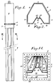
- Fig. 1 schematically represents part of the installation of the invention; this part will referred to as “density measurement device” (abbreviated as device).
- device density measurement device
- Several devices can be installed on the same self-supporting dredge.
- a sheath 1, made of steel and perfectly sealed, is installed, substantially vertically, in a well of a self-supporting dredge not shown in FIG. 1. It has a substantially U-shaped section (see Fig. 2) and extends over the greater part of the height of the device, determining between its two branches a sort of vertical corridor 2.
- the sheath 1 is closed at its lower part and opens by its upper part into a chamber 3 which has a square section and which is bordered, at its upper end, with a flange 4 provided with perforations for the passage of bolts.
- the installation of the invention makes it possible to continuously measure the density of dredging materials which accumulate during dredging in the corridor 2 comprised between the branches of the sheath 1 (see FIG. 11).
- the walls 7 to 10 of the sheath 1 are 12 mm thick, while the internal lateral walls 11 and the wall 12 which together form the passage 2 are only 6 mm thick.
- Two angle sections 13, facing one another inside the sheath 1, are integral with the wall 12 and extend longitudinally along the height of the sheath 1 (see also Fig. 14).
- Figs. 3 to 5 schematically illustrate different positions of the main elements of a device of the installation of the invention for the continuous measurement of densities.
- the sheath 1 of this device is not shown.
- the height of the device (about 15 m) is much greater than its width (about 60 cm), and that therefore the various elements are not all represented on the same scale.
- This probe 14 is mounted on a carriage 15 which, in operation, moves along a vertical path in the sheath 1 along rails 16 (only one of which is visible in FIGS. 3 to 5), between a position 15 a ( Fig. 3) where it actuates a lower limit switch 17 and a position 15 c (Fig. 5) where it actuates an upper limit switch 18.
- the carriage 15 remains, at rest, in position 15 c .
- the carriage 15 can move from position 15 a to position 15 c and vice versa, between the limit switches 17 and 18, covering approximately 14 m in 50 to 60 seconds.
- Fig. 4 shows an intermediate position 15 b of carriage 15.
- the probe 14 performs measurements during the movement of the carriage 15 from position 15 a to position 15c.
- the mobile elements are designated by their reference number followed by the letter a , b or c depending on the position in which they are represented.
- the movements of the carriage 15 are controlled by a double-acting hydraulic cylinder 19 via a metal cable (not shown in Figs. 3 to 5) which passes through pulleys (see Fig. 6) and is secured to the carriage 15.
- the jack 19 is supplied with hydraulic fluid by two pipes 20 and 21 which open respectively at its lower part and at its upper part.
- the piston rod 22 moves between a retraction position 22 a in the cylinder 19 (Fig. 3) and a position 22 c in which it is extended as far as possible (Fig. 5).
- carriage 15 moves in the opposite direction from the piston rod 22, and at a speed four times greater.
- the probe 14 carried by the carriage 15 is connected to the computer-assisted management assembly, which controls and controls the operation of the entire installation and is installed on board the self-supporting dredge (see Fig. 15). This connection is made using an electric cable not shown in Figs. 3 to 5.
- FIG. 6 schematically shows the arrangement of the metal cable 23 and the electric cable 24 on a series of pulleys.
- the piston rod 22 has been shown in solid lines, in a position 22 b similar to that of FIG. 4. It has also been shown in dotted lines in the extreme positions 22 a (see Fig. 3) and 22 c (see Fig. 5). Similarly, the carriage 15 which is shown in solid lines in its position 15 b (which corresponds to the position 22 b of the piston rod) is also shown in dotted lines in its extreme positions 15 a and 15 c .
- the piston rod 22 drives the carriage 15 by means of a metal cable 23 (shown in phantom) which is stowed there and which passes over a series of pulleys.
- a horizontal axis 25 on which four pulleys 26, 27, 28 and 29 are mounted is integral with the end of the piston rod 22.
- the pulleys 30 and 31 (at the top of the mechanism) as well as the pulleys 32 and 33 (at the lower part of the mechanism) are each mounted on a horizontal axis integral with the fixed part 34 of the device, shown diagrammatically in FIG. 6 per a rectangle.
- the two ends of the metal cable 23 are clamped respectively in two cable clamps 35 and 36 integral with the fixed part 34 of the device.
- the metal cable 23 passes successively over the pulleys 26, 30, 29 and 31, the carriage 15 (to which it is secured), and over the pulleys 32, 28, 33 and 27, to reach the clamp cable 36.
- the electric cable 24 is shown in FIG. 6 in broken lines. It is arranged in such a way that its end connected to the probe 14 can follow the movements of the latter. To this end, the electric cable 24 also passes over a series of pulleys.
- the pulleys 37 and 38 are mounted on a horizontal axis 39 secured to the end of the piston rod 22.
- the pulleys 40 and 41 (at the top of the mechanism) are mounted on a horizontal axis secured to the fixed part 34 of the device.
- the electric cable 24 passes successively over the pulleys 40, 37, 41 and 38 to then pass through a sleeve 42 through which it leaves the fixed part 34 of the device for arriving at the management assembly (not shown) which controls the general operation of the installation (see Fig. 15).
- FIG. 6 is a diagram in which the dimensions and reciprocal positions of the elements represented do not correspond to reality, this FIG. 6 whose sole purpose is to show the operating principle of the mechanical part of the device.
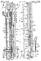
- Fig. 7 is a detailed view in elevation, with interruptions, of all the elements contained in the sheath 1, in the position shown diagrammatically in FIG. 3.
- Figs. 7A and 7B each show part of this device, the part shown in FIG. 7A surmounting the part shown in FIG. 7B.
- Figs. 8, 9 and 10 are sections respectively along lines VIII-VIII, IX-IX and X-X of this FIG. 7.
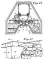
- Fig. 11 is a sectional view along line XI-XI of FIG. 7. Certain elements of the transmission mechanism have not been shown in this FIG. 11. By cons, there is shown the sheath 1 which was not shown in FIG. 7, so as to show the arrangement of the various elements of the device from the inside of this sheath 1.
- the metal section 44 which consists of two parallel plates of unequal widths joined by two other plates arranged perpendicularly, carries the two rails 16, each bolted to one of the edges of its widest plate.
- the metal profile 44 is introduced through its narrower plate, between the two angle profiles 13 (shown in Figs 2 and 12) which serve as a guide. This arrangement allows easy assembly of the device in the workshop, and rapid disassembly for maintenance and repair.
- the fixed elements of the device contained in the sheath 1 are connected, directly or indirectly, to this metal profile 44 which extends longitudinally over the height of the sheath 1. It should be noted that the total length of the profile 44 is more greater than the length of the square sections 13 and that the height of the sheath 12 and that the carriage 15 may, for maintenance reasons, continue its race upwards along the rails 16, beyond the interruption of upper limit switch 18.
- a C 45 piece is bolted on the one hand to the widest flat of the profile 44, and on the other hand to a metal structure 46 which serves as a support for the pulleys 32 and 33 and as a guide for the yoke 43 which carries the pulleys 26, 27, 28, 29, 37 and 38.
- This metallic structure 46 which occurs in its assembly as a long openwork cage of rectangular cross section, is surmounted by a plate 47, bolted itself to another plate 48, integral with the cylinder of the jack 19. As can be seen in FIG. 8, these plates 47 and 48 are crossed four times by the metal cable 23, one end of which is blocked in the cable clamp 35 secured to the plate 48.
- the jack 19 is fixed to the metal profile 44 by means of a set of metal parts 49, 50, 51 and 52.
- the part 52 also carries the axis of the pulley 31.
- the profile 44 carries the two rails 16, each bolted to one of the edges of its widest flat.
- the carriage 15 which carries the probe 14 can move along these rails 16, bolted to the profile 44 by virtue of the rollers 53 with which it is provided (see also FIG. 12).
- the position of the probe 14 in the sheath 1 can be determined at any time using an angular position encoder 54 shown in Figs. 7, 10 and 13.
- This coder 54 comprises an optically coded disc and an internal optical and electronic device.
- the disc is mechanically coupled to the pulley 31, the groove of which accommodates the metal cable 23 which drives the carriage 15.
- the optical and electronic device produces 1000 electrical pulses for each revolution of the pulley 31 and transmits these pulses to the assisted management assembly by computer (see Fig. 15).
- the tension of the metal cable 23 is adjusted by means of a tension regulating device 55 shown in FIG. 7.
- This tension regulating device 55 is mounted on the metallic structure 46 and carries the cable clamp 36.
- the tension exerted on the metallic cable 23 can also be adjusted by means of a threaded rod which carries the pulley 30.
- the tension of the electric cable 24 is adjusted by means of a voltage regulating device 56 mounted to the part upper of the cylinder of the jack 19 and carrying a cable clamp 57 (from which the electric cable 24 leaves the device passing through the sleeve 42).
- Fig. 7 also shows a small grooved wheel 58 mounted on a horizontal axis carried by a part 59 integral with the part 51.
- This small grooved wheel 58 guides the metal cable 23 and, from the pulley 31, brings it vertically its point of attachment to the carriage 15.
- the transmission radioactive probe 14 which is shown in Figs. 3 to 7 will be described in more detail with reference to Figs. 11 and 12.
- the probe 14 which is mounted on the carriage 15 and which therefore moves with the latter in the U-shaped sheath 1, comprises a radioactive source 60 and a nuclear detector designated under the general reference 61. As shown in FIG. 11, the source 60 is housed in one of the branches of the U, while the detector 61 is located opposite the latter, in the other branch of the U.
- the source 60 is included in a bolt 62 inserted in a source holder block 63 which consists of a steel box filled with lead and which is provided with a collimator hole 64 directed towards the detector 61.
- the latter is carried so analogous in a metal detector block 65, which is provided with a window 66 facing the source 60.
- the gamma rays emitted by the source 60 and passing through the collimator hole 64 cross the vertical corridor 2 and pass through the window 66 to reach the detector 61 following a horizontal trajectory.
- the internal lateral walls 11 of the sheath 1 are crossed by gamma rays, which therefore makes it possible to carry out radiation absorption measurements on a material external to the device, included in the vertical corridor 2, while preserving this device from direct contact with the environment studied.
- Part of the gamma radiation emitted by the source 60 is deflected or absorbed by the solid particles in suspension in the water-sediment mixture contained in the vertical corridor 2 and therefore does not or does not directly reach the nuclear detector 61 which therefore mainly records the part of the gamma radiation which is not deflected or absorbed by the medium traversed.
- the residual, non-absorbed gamma radiation emitted by the source 60 and captured by the detector 61 can then be converted by the computer-assisted management assembly to measure the density of the water-sediment mixture.
- the radioactive source 60 consists of a 137Cs ceramic bead with double encapsulation. This 5mC i source is capable of emitting radiation of 0.661 MeV. Since the half-life of 137Cs is 30 years, the drop in gamma ray emission is only around 2.4% per year, which means that the emission rates are practically constant for three or four months.
- radioactive sources can be used.
- devices for closing the collimator hole 64 when the probe 14 is not in service can be provided.
- the nuclear detector 61 consists of a scintillation counter. It is equipped with a NaI (Tl) crystal, a photomultiplier and an electronic power supply and amplification unit. These elements are brought together in a sealed cylindrical case 67 made of PVC mounted on the carriage 15.
- the photomultiplier and the electronic supply and amplification unit convert these photons into electrical pulses of a suitable form to be sent to an electronic adaptation unit forming part of the management assembly (see Fig. 15) .
- Fig. 13 is a view similar to FIG. 7 but the mechanical elements of the device are shown there in the position of FIG. 5, that is to say that the carriage 15 is here in its position 15 c , while the piston rod 22 of the jack 19 and the yoke 43 which it carries are in their low position 22 c and 32 c . It will be noted that the carriage 15 is in contact with the upper limit switch 18.
- Fig. 14 is a perspective view of the chamber 3, viewed obliquely from above. In this Fig. 14 (as in FIG. 2), the sheath 1 is shown empty of any other element of the device.
- Chamber 3 is delimited laterally by four walls 68, 69, 70 and 71 and its bottom consists of three horizontal walls 72, 73 and 74.
- the walls 10, 11 and 12 of the sheath 1 extend upwards inside the chamber 3, thus delimiting, with the horizontal wall 74, the vertical wall 68 and a part of each vertical walls 69 and 71, a calibration tank 75.
- the probe 14, brought into the chamber 3 can be calibrated with different media of known density, poured into the calibration tank 75.
- a leak detector device (not shown in FIGS. 1 to 14) installed in the sheath 1 is connected to the management assembly which, in the event of leak detection, controls the immediate raising of the carriage 15 into bedroom 3.
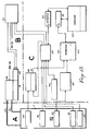
- FIG. 15 The general operation of the installation according to the invention will be better understood by referring to FIG. 15, in which a single measuring device is shown.
- This installation is distributed, on the self-supporting dredge, in three different sites.
- the sheath 1 of the measuring device is located in a dredge well self-supporting, symbolized in FIG. 15 with the letter A.
- a computer-assisted management system, designated by the letter C, is installed on the control gateway where it can be started and controlled by an operator.
- the sheath 1 contains the mechanism which produces the reciprocating movement from bottom to top of the probe 14 in this sheath 1. This movement is actuated by the hydraulic cylinder 19 (not shown in Fig. 15) which is connected to the hydraulic unit 76 via lines 20 and 21.
- the hydraulic unit 76 which is connected to the hydraulic cylinder 19, causes the probe 14 to rise and fall by means of electrically controlled hydraulic distributors 79 which, via relays 80, can be actuated automatically by the interface of control 81 of the management assembly C during normal operation, or manually by means of switches not shown in FIG. 15 which can be used during maintenance, repair or test operations.
- the electrically operated hydraulic distributors 79 also make it possible to adjust the speed of movement of the carriage 15.
- the computer-assisted management assembly C receives the signals transmitted to it by the five detectors installed in the sheath 1. It controls the ascent and descent of the probe 14 as a function, signals which it receives from the limit switches lower 17 and 18 and the leak detector 78.
- the management assembly C also processes all the signals it receives from the nuclear detector 61, the lower limit switches 17 and upper limit switches 18 and the angular position encoder 54, to deduce therefrom density and total weight of dredged material loaded into the boat's well and it displays the results of these measurements.
- control interface 81 the adaptation unit t d supply 82, the counting interface 83 and the position indicator 85 are multi-channel.
- the amplified electrical pulses coming from the nuclear detector 61 are received by the adaptation and supply unit 82 which has several functions. It is used first of all to supply the supply voltages required by the nuclear detector 61. It makes it possible to measure and adjust the supply voltages and electrical pulses received. Finally, it transforms the electrical input pulses received from the nuclear detector 61 into electrical output pulses adapted to be received and processed by the counting interface 83.
- This counting interface 83 is provided with a device for preselecting the counting time 84 during which the pulses coming from the detector are counted. These counting periods will, for example, be set for a duration of 0.4 s. While the probe 14 is rising in the sheath 1, the pulses received by the counting interface 83 will be counted at regular intervals (determined by the angular position encoder 54 and the preselected position indicator), each time for a duration of 0.4 s. The pulses counted by the counting interface 83 are transmitted to the computer 88 which transforms them into density and total weight measurements and displays these measurements by means of a visual display device and possible peripheral devices.
- the carriage 15 Before starting the installation, the carriage 15 is in the rest position 15 c , in which it is in contact with the upper limit switch 18. After a static check of the detector 16 by the Intermediate of the management assembly C and the computer, the carriage 15 is sent to position 15a where it actuates the lower limit switch 17. The counter of the position indicator 85 is then set to zero by the control interface 81. The start signal of the actual measurement process is given by actuating the start of loading switch 87. Therefore, the carriage 15 is sent upwards until it actuates the upper limit switch 18 and the carriage is returned downwards in a continuous process.
- the position indicator 85 During the movement of the carriage 15 upwards, the position indicator 85 totals the pulses electrics received from the angular position encoder 54 and continuously displays this total on its digital counter until the carriage 15, in position 15 c , again actuates the upper limit switch 18. It should be noted that during from the descent of the carriage 15, the position indicator 85 continuously counts the pulses received from the angular position encoder 54 of the total number of pulses which had been recorded when the carriage 15 was in position 15 c .
- the angular position encoder 54 emits 1000 pulses for each revolution of the pulley 31. In an example of installation according to the invention, the angular position encoder 54 emits approximately 24,000 pulses for a path of the carriage 15 of 14 meters between the moment where it is in contact with the lower limit switch 17 and when it actuates the upper limit switch 18.
- the position indicator 85 is provided with a position preselection device 86 which emits a signal at regular intervals, during the ascent of the carriage 15, each time a predetermined number of pulses is received from the encoder. angular position 54.
- the total path (14 m) of the probe 14 is thus divided into sections or "windows" of identical length.
- the output signals emitted by the position preselection device 86 are sent to the counting interface 83 which, after reception of each signal, receives and totals for 0.4 s the pulses coming from the adaptation unit and d 82.
- the counting interface 83 stores the counting rates recorded in all of the "Windows". At its output, the counting interface 83 therefore delivers the numbers of pulses counted during a period of 0.4 s in each of the "windows". These pulses are transmitted to the computer 88, via the input / output gate 90.
- the probe 14 As the probe 14 moves from bottom to top at a speed of about 22 to 25 cm / s, it travels about 8.8 to 10 cm in 0.4 s (counting period in each window). After each counting period, the probe 14 therefore has to travel a distance of 2.4 to 3.6 cm before the next counting period begins (in the following "window"). The time from 0.10 to 0.16 s that this 2.4 to 3.6 cm course lasts is free for the transmission of data from the nuclear detector 61 to the counting interface 83.
- the control interface 81 transfers to the computer 88 the information from the start and end of load switches 87, the lower 17 and upper 18 limit switches and the leak detector 78. Depending on the information thus received and of the program with which it is provided, the computer 88 sends instructions to the control interface 81 for the movement of the carriage 15 upwards or downwards. As a result of these instructions received, the control interface 81 actuates, in an appropriate manner, the relays 80 which control the operation of the hydraulic distributors 79 of the hydraulic group 76.
- the computer 88 controls, according to its program, the return of the carriage 15, downwards, each time the latter actuates the end of loading switch. stroke 18, and sending the carriage 15 upwards each time the latter actuates the lower limit switch 17. This reciprocating movement from top to bottom, and back, of the carriage 15 continues until when the end of charge switch 87 is set to the position stop.
- each pulse delivered by the angular position encoder 54 corresponds to a movement of the carriage 15 over a distance of only about 0.58 mm.
- the computer 88 is provided with various peripherals such as: color video screen, printer, memory disk drives and tape recorder. These last two elements constitute the external memory of computer 88.
- the loading status of the well of the dredger boat On the video screen are graphically displayed the loading status of the well of the dredger boat, as a function of time, and also other parameters such as the moment of start of loading, intermediate times, loading speed, weight total load, the start time of overflow, etc.
- Another embodiment of the movement mechanism can consist of an electric motor provided with an electromechanical brake, speed reducer, a cable drum and an angular position encoder.
- the combination of the electric motor and the speed reducer can be a gear motor.
- a combined cable ensuring mechanical traction and the transmission of electrical signals is mounted on the drum and is connected to the carriage 15.
- the transmission of the electrical signals from the carriage 15 to the management assembly C is carried out by means of a unit with slip rings incorporated in the drum.
- the electric motor controls the upward and downward movement of the carriage according to the program and the limit switches 17 and 18 provided at the upper and lower parts of the sheath 1.
- the cable is held taut by the weight of the carriage 15.
- a brake retainer keeps the carriage 15 in place when the system stops.
- the carriage 15 is fixed to the rails 16 by rollers 53 as in the case of the hydraulically controlled system.
- a mechanical locking device provided on the carriage 15 is activated in the event of a cable break, which prevents the carriage 15 from falling.
- the system can be provided with an electronic frequency control or with a four-quadrant thyristor control with an associated tachometer generator on the motor.
- the angular position encoder measures, as in the case of the hydraulic system, the position of the carriage 15 between the upper 15 c and lower 15 a positions .
Landscapes
- Physics & Mathematics (AREA)
- Health & Medical Sciences (AREA)
- Life Sciences & Earth Sciences (AREA)
- Chemical & Material Sciences (AREA)
- Analytical Chemistry (AREA)
- Biochemistry (AREA)
- General Health & Medical Sciences (AREA)
- General Physics & Mathematics (AREA)
- Immunology (AREA)
- Pathology (AREA)
- Measurement Of Radiation (AREA)
- Analysing Materials By The Use Of Radiation (AREA)
Claims (27)
- Vorrichtung zum kontinuierlichen Messen der Dichte und des Gesamtgewichts des in einem Schacht eines Schwimmbaggers enthaltenen Baggermaterials mit mindestens einer wasserdichten radioaktiven Sonde (14), die in einem wasserdichten Mantel (1) untergebracht ist, der etwa in der Vertikalen im Schacht angeordnet ist, wobei die Sonde (14) eine radioaktive Quelle (60) und einen Nukleardetektor (61) aufweist, wobei der Detektor (61) mit Mitteln zum Umwandeln der Kernstrahlung in analysierbare Daten ausgestattet ist, und wobei die Vorrichtung gekennzeichnet ist durch:(i) mindestens eine Einrichtung, von denen jede aufweist- den Mantel (1), der einen im wesentlichen U-förmigen Querschnitt aufweist, wobei die beiden Arme des U eine Art vertikalen halb-geöffneten Durchgang (2) bilden;- die radioaktive Sonde (14), die eine Strahlungssonde ist, wobei die radioaktive Quelle (60) in Richtung des Nukleardetektors (61) ausstrahlt, und wobei die radioaktive Quelle (60) und der Nukleardetektor (61) einander gegenüber jeweils in einem Arm des U angeordnet sind, und wobei der Nukleardetektor (61) mit Mitteln zum Umwandeln der Kernstrahlung in Photonen und danach in elektrische Impulse und zum anschließenden Verstärken dieser Impulse ausgestattet ist;- Führungseinrichtungen (16, 53), die es erlauben, die Sonde (14) entlang einer vertikalen Bahn in dem Mantel (1) zu führen;- Einrichtungen zum Verschieben der Sonde (14) nach oben und nach unten entlang der vertikalen Bahn in dem Mantel (1);- Mittel (54) zur Bestimmung der Position der Sonde (14) in dem Mantel (1);(ii) eine computergestützte Steuerungsanordnung (C), wobei diese Steuerungsanordnung (C) in der Lage ist, die Zeit zu messen und aufzuzeichnen, die von den Mitteln (54) zur Positionsbestimmung der Sonde(n) (14) in dem Mantel oder den Mänteln (1) gesammelten Daten zu empfangen und zu verarbeiten, die Daten, die von dem oder den Nukleardetektor(en) (61) in Form von elektrischen Impulsen gesammelt werden, welche im Verlauf von regelmäßigen festgelegten Intervallen gezählt und in der Dichte entsprechenden Messungen umgewandelt werden, zu empfangen und zu verarbeiten, aus diesen Messungen das Gesamtgewicht des in dem Schacht enthaltenen Baggermaterials zu berechnen, alle Daten in einem Hauptspeicher aufzubewahren, die Analyse und das Ergebnis dieser Messungen mit Hilfe einer visuellen Anzeigevorrichtung und/oder eines Druckers darzustellen, und in Abhängigkeit von einem vorgewählten Programm das allgemeine Funktionieren der Einrichtung zu regeln und zu steuern;(iii) Mittel zum Übertragen von elektrischen Impulsen an die Steuerungsanordung (C), wobei die Impulse von dem oder den Nukleardetektor(en) (61) und von den Mitteln (54) zur Bestimmung der Position der Sonde(n) (14) in dem Mantel oder den Mänteln (1) geliefert werden.
- Vorrichtung nach Anspruch 1 dadurch gekennzeichnet, daß der Mantel (1) aus Stahl hergestellt ist.
- Vorrichtung nach einem der vorhergehenden Ansprüche, dadurch gekennzeichnet, daß die radioaktive Quelle (60) eine Gammastrahlen-Quelle ist.
- Vorrichtung nach Anspruch 3, dadurch gekennzeichnet, daß die radioaktive Quelle (60) aus einer doppelten verkapselten Keramikperle mit ¹³⁷Cs besteht.
- Vorrichtung nach einem der vorhergehenden Ansprüche, dadurch gekennzeichnet, daß der Nukleardetektor (61) aus einem Szintillationszähler besteht.
- Vorrichtung nach Anspruch 5, dadurch gekennzeichnet, daß die Mittel zum Umwandeln der Kernstrahlung in Photonen aus einem NaI (Tl)-Kristall bestehen.
- Vorrichtung nach Anspruch 6, dadurch gekennzeichnet, daß die Mittel zum Umwandeln der Photonen in elektrische Impulse und die Mittel zum Verstärken der elektrischen Impulse aus einem Photovervielfacher bzw. aus einer elektronischen Versorgungs- und Verstärkungseinheit bestehen.
- Vorichtung nach einem der vorhergehenden Ansprüche, dadurch gekennzeichnet, daß die Sonde (14) auf einem Wagen (15) angeordnet ist.
- Vorrichtung nach Anspruch 8, dadurch gekennzeichnet, daß die Führungseinrichtungen der Sonde (14) aus senkrecht in dem Mantel (1) angeordneten metallischen Schienen (16) und aus an dem Wagen (15) montierten Rollen (53) bestehen.
- Vorrichtung nach Anspruch 9, dadurch gekennzeichnet, daß die Einrichtungen zum Verschieben der Sonde (14) entlang einer vertikalen Bahn in dem Mantel (1) einen Zylinder (19) mit einer vertikal in dem Mantel (1) beweglichen Kolbenstange (22) aufweisen.
- Vorrichtung nach Anspruch 10, dadurch gekennzeichnet, daß die Einrichtungen zum Verschieben der Sonde (14) entlang einer vertikalen Bahn in dem Mantel (1) eine Übertragungseinrichtung aufweisen, die geeignet ist, die Bewegung der Kolbenstange (22) auf den Wagen (15) zu übertragen, wobei der Umfang dieser Bewegung vervielfacht wird.
- Vorrichtung nach Anspruch 11, dadurch gekennzeichnet, daß die Übertragungseinrichtung Antriebsscheiben (26, 27, 28, 29), die auf einer mit dem Ende der Kolbenstange (22) verbundenen Achse (25) angeordnet sind, feste und mit dem Mantel verbundene Antriebsscheiben (30, 31, 32, 33) und ein metallisches Kabel (23) aufweisen, das am Wagen befestigt ist und über die Antriebsscheiben (26, 27, 28, 29, 30, 31, 32, 33) läuft.
- Vorrichtung nach einem der Ansprüche 11 und 12, dadurch gekennzeichnet, daß die Übertragungseinrichtung derart ausgebildet ist, daß jede Verschiebung der Kolbenstange (22) eine Verschiebung der Sonde (14) in umgekehrter Richtung mit sich bringt.
- Vorrichtung nach einem der Ansprüche 12 und 13, dadurch gekennzeichnet, daß die Mittel zum Bestimmen der Position der Sonde (14) in dem Mantel (1) eine Kodierscheibe (54) mit einer optisch kodierten Scheibe und einer eingebauten optischen und elektronischen Vorrichtung aufweisen, wobei die Scheibe mechanisch an eine der festen Antriebscheiben (31), über die das metallische Kabel (23) verläuft, gekoppelt ist.
- Vorrichtung nach Anspruch 9, dadurch gekennzeichnet, daß die Einrichtungen zum Verschieben der Sonde (14) entlang der vertikalen Bahn in dem Mantel (1) einen Elektromotor mit einer elektromechanischen Bremse, einen Drehzahlminderer und eine Seiltrommel für das Kabel aufweisen.
- Vorrichtung nach Anspruch 15, dadurch gekennzeichnet, daß sie Mittel zum Regeln der Verschiebegeschwindigkeit der Sonde (14) aufweist, wobei diese Mittel eine elektronische Frequenzsteuerung aufweisen.
- Vorrichtung nach Anspruch 15, dadurch gekennzeichnet, daß sie Mittel zum Regeln der Verschiebegeschwindigkeit der Sonde (14) aufweist, wobei diese Mittel einen Vierquadranten-Regler und einen auf dem Elektromotor angeordneten Tachosignalgeber aufweisen.
- Vorrichtung nach einem der Ansprüche 15, 16 und 17, dadurch gekennzeichnet, daß die Mittel zum Bestimmen der Position der Sonde (14) in dem Mantel (1) eine Kodierscheibe mit einer optisch kodierten Scheibe und einer eingebauten optischen und elektronischen Vorrichtung aufweisen, wobei die Scheibe mechanisch an ein drehbares Teil gekoppelt ist, dessen Bewegung mit der Verschiebung der Sonde (14) in Zusammenhang steht.
- Vorrichtung nach einem der vorhergehenden Ansprüche, dadurch gekennzeichnet, daß sie ferner an den Enden der von der Sonde (14) durchlaufenen vertikalen Bahn in dem Mantel (1) untere (17) und obere (18) Endstellungsschalter aufweist, die in der Lage sind, Daten an die computergestützte Steuerungsanordnung (C) zu übertragen.
- Vorrichtung nach Anspruch 19, dadurch gekennzeichnet, daß die Steuerungsanordnung (C) mit einem Programm versehen ist, das es insbesondere erlaubt, daß der die kontinuierlichen Messungen vornehmende Nukleardetektor (61) diese zur Steuerungsanordnung (C) überträgt, wenn die Sonde (14) entlang einer vertikalen Bahn in dem Mantel (1) vom unteren Endstellungsschalter (17) zum oberen Endstellungsschalter (18) verschoben wird und an ihre Ausgangsposition zurückkehrt, ohne Messungen durchzuführen.
- Vorrichtung nach einem der Ansprüche 19 und 20, dadurch gekennzeichnet, daß über dem Mantel (1) eine Kammer (3) angeordnet ist, die oberhalb des höchsten Füllniveaus des Schachtes angebracht ist.
- Vorrichtung nach Anspruch 21, dadurch gekennzeichnet, daß die Kammer (3) geeignet ist, den Wagen (15) und die Sonde (14) aufzunehmen und während der Zeit, in der die Vorrichtung nicht arbeitet, zur Lagerung der beiden dient.
- Vorrichtung nach Anspruch 22, dadurch gekennzeichnet, daß der obere Endstellungsschalter (18) oberhalb des Niveaus der Kammer (3) angeordnet ist.
- Vorrichtung nach einem der Ansprüche 21 bis 23, dadurch gekennzeichnet, daß die Kammer (3) einen Kalibrierbehälter (75) umfaßt, der sich in der Verlängerung des Durchganges (2) zwischen den U-förmigen Armen des Mantels (1) befindet, wobei dieser Kalibrierbehälter (75) geeignet ist, Medien mit bekannter Dichte zu enthalten, die der Kalibrierung der Sonde (14) dienen.
- Vorrichtung nach einem der Ansprüche 21 bis 24, dadurch gekennzeichnet, daß sie ferner einen Lecksucher (78) aufweist, der in der Lage ist, in dem Mantel (1) das Vorhandensein von infolge eines Lecks dort eingedrungener fester oder flüssiger Materie festzustellen und eine entsprechende Information an die Steuerungsanordnung (C) zu übermitteln.
- Vorrichtung nach Anspruch 25, dadurch gekennzeichnet, daß die Steuerungsanordnung (C) in der Lage ist, im Falle eines Lecks zu steuern, daß die Sonde (14) sofort in die Kammer (3) gesandt und die Funktion der Vorrichtung unterbrochen wird.
- Vorrichtung nach einem der vorhergehenden Ansprüche, dadurch gekennzeichnet, daß die Steuerungsanordnung (C) ferner einen externen Speicher enthält.
Applications Claiming Priority (2)
| Application Number | Priority Date | Filing Date | Title |
|---|---|---|---|
| BE9000499A BE1004310A3 (nl) | 1990-05-11 | 1990-05-11 | Installatie voor de continue meting van de dichtheid en het totale gewicht van materialen geladen in het laadruim van een hopperzuiger. |
| BE9000499 | 1990-05-11 |
Publications (2)
| Publication Number | Publication Date |
|---|---|
| EP0456629A1 EP0456629A1 (de) | 1991-11-13 |
| EP0456629B1 true EP0456629B1 (de) | 1996-03-13 |
Family
ID=3884789
Family Applications (1)
| Application Number | Title | Priority Date | Filing Date |
|---|---|---|---|
| EP91870075A Expired - Lifetime EP0456629B1 (de) | 1990-05-11 | 1991-05-08 | Einrichtung zur kontinuierlichen Messung der Dichte und des Gesamtgewichts des Inhaltes des Laderaums eines Laderaumbaggers |
Country Status (5)
| Country | Link |
|---|---|
| EP (1) | EP0456629B1 (de) |
| BE (1) | BE1004310A3 (de) |
| DE (2) | DE69117799T2 (de) |
| ES (1) | ES2027196T3 (de) |
| SG (1) | SG45307A1 (de) |
Families Citing this family (2)
| Publication number | Priority date | Publication date | Assignee | Title |
|---|---|---|---|---|
| NL2005373C2 (nl) * | 2010-09-20 | 2012-03-22 | Ihc Syst Bv | Werkwijze en inrichting voor het bepalen van een volume van een bezonken bed in een mengsel in een laadruimte. |
| WO2014014350A1 (en) | 2012-07-17 | 2014-01-23 | Ihc Systems B.V. | Method and device for determining a height of a settled bed in a mixture in a loading space |
Family Cites Families (5)
| Publication number | Priority date | Publication date | Assignee | Title |
|---|---|---|---|---|
| JPS5571964A (en) * | 1978-11-24 | 1980-05-30 | Toshiba Corp | Method of and device for measuring sludge boundary surface for radioactive substance storage tank |
| NL7900161A (nl) * | 1979-01-09 | 1980-07-11 | Ir Romke Van Der Veen | Werkwijze en inrichting voor het opnemen van een van de dichtheid van een mengsel afhankelijke meetwaarde. |
| FR2455275A1 (fr) * | 1979-04-27 | 1980-11-21 | Rech Geolog Miniere | Procede et appareil de mise en oeuvre pour la mesure de la densite apparente de carottes de forage et de la densite de colonnes de pulpes par absorption de rayons g |
| NL8001034A (nl) * | 1980-02-20 | 1981-09-16 | Ihc Holland Nv | Inrichting en werkwijze voor het vaststellen van de beunbelading van een hopperzuiger. |
| BE896481A (nl) * | 1983-04-15 | 1983-08-01 | Bastin A L | Meetstaaf op basis van detectie van gereflecteerde gammastralen voor het meten van de densiteit of het volumegewicht van de baggerspecie in het ruim van baggerschepen. |
-
1990
- 1990-05-11 BE BE9000499A patent/BE1004310A3/nl not_active IP Right Cessation
-
1991
- 1991-05-08 DE DE69117799T patent/DE69117799T2/de not_active Expired - Lifetime
- 1991-05-08 ES ES91870075T patent/ES2027196T3/es not_active Expired - Lifetime
- 1991-05-08 SG SG1996003212A patent/SG45307A1/en unknown
- 1991-05-08 DE DE199191870075T patent/DE456629T1/de active Pending
- 1991-05-08 EP EP91870075A patent/EP0456629B1/de not_active Expired - Lifetime
Also Published As
| Publication number | Publication date |
|---|---|
| EP0456629A1 (de) | 1991-11-13 |
| DE69117799T2 (de) | 1996-10-31 |
| BE1004310A3 (nl) | 1992-10-27 |
| DE69117799D1 (de) | 1996-04-18 |
| DE456629T1 (de) | 1992-05-21 |
| ES2027196T3 (es) | 1996-05-01 |
| ES2027196T1 (es) | 1992-06-01 |
| SG45307A1 (en) | 1998-01-16 |
Similar Documents
| Publication | Publication Date | Title |
|---|---|---|
| EP0080418B1 (de) | Verfahren und Einrichtung zur Prüfung eines Brennelementbündels eines Kernreaktors | |
| EP0307271B1 (de) | Vorrichtung zur Charakterisierung von spaltbarem Material, welche einen im Innern eines Gammastrahlungsdetektionsszintillators eingebetteten Neutronenstrahlungsdetektor enthält | |
| US5686674A (en) | System for characterizing surfaces of pipes, ducts or similar structures | |
| KR102720973B1 (ko) | 배관 용접부 검사장치 | |
| EP3701222A1 (de) | Verfahren und vorrichtung zur messung von abmessungen durch röntgenstrahlen auf in einer linie verlaufenden leeren glasbehältern | |
| WO2011151530A1 (fr) | Procede et dispositif de mesure de l'epaisseur d'une couche de revetement sur une bande en defilement | |
| EP0187093A1 (de) | Automatischer Regenmesser | |
| EP0766265B1 (de) | Verfahren und Vorrichtung zum Messen mindestens einer charakterisierenden Länge eines Brennstabs an der Peripherie eines Kernbrennstabbündels | |
| EP0456629B1 (de) | Einrichtung zur kontinuierlichen Messung der Dichte und des Gesamtgewichts des Inhaltes des Laderaums eines Laderaumbaggers | |
| WO2001082307A1 (fr) | Procede et dispositif de mesure du diametre d'un crayon peripherique d'un assemblage de combustible d'un reacteur nucleaire | |
| EP0424265B1 (de) | Vorrichtung zur Messung der Strahlungsverseuchung von grossen Objekten | |
| FR2688885A1 (fr) | Procede de diagraphie chimique d'un liquide et installation de diagraphie chimique pour la mise en óoeuvre de ce procede. | |
| FR2487878A1 (fr) | Machine de nettoyage de la couche de ballast d'une voie ferree comprenant des dispositifs de mesure, d'enregistrement et le cas echeant d'affichage | |
| CN215767283U (zh) | 一种水文地质用水位观测设备 | |
| FR2613116A1 (fr) | Appareil pour inspecter le profil d'une tige, notamment une tige de commande utilisee dans un reacteur nucleaire a eau pressurisee | |
| FR2754053A1 (fr) | Procede et dispositif de mesure de deformation de tube guide | |
| EP0121463B1 (de) | Verfahren und Vorrichtung zur Informationsermittlung über organische oder minerale Stoffe in geologischen Formationen | |
| WO1994001747A1 (fr) | Dispositif indicateur du debit d'une fuite d'un circuit primaire de reacteur nucleaire | |
| EP0207038B1 (de) | Nachgezogenes Dichtemessgerät | |
| FR2752639A1 (fr) | Dispositif de caracterisation individuelle d'assemblages de combustible nucleaire et installation de controle non destructif comprenant un tel dispositif | |
| FR2480723A1 (fr) | Installation pour la prise d'echantillons dans une masse de produit | |
| EP0010498B1 (de) | Verfahren und Vorrichtung zur Abschätzung der Fahrbahndeformation unter Last | |
| FR2460475A1 (fr) | Installation et dispositif pour la determination in situ de l'evapotranspiration d'un couvert vegetal par la methode du bilan d'energie et la densite de flux de masse de gaz carbonique | |
| GB2456302A (en) | Screening system and method for scanning a target for radioactive isotopes | |
| EP0562146A1 (de) | Verfahren und Vorrichtung für die Diagraphie einer Erdbohrung |
Legal Events
| Date | Code | Title | Description |
|---|---|---|---|
| PUAI | Public reference made under article 153(3) epc to a published international application that has entered the european phase |
Free format text: ORIGINAL CODE: 0009012 |
|
| AK | Designated contracting states |
Kind code of ref document: A1 Designated state(s): DE DK ES FR GB IT NL |
|
| ITCL | It: translation for ep claims filed |
Representative=s name: UFFICIO TECNICO ING. A. MANNUCCI |
|
| TCNL | Nl: translation of patent claims filed | ||
| GBC | Gb: translation of claims filed (gb section 78(7)/1977) | ||
| 17P | Request for examination filed |
Effective date: 19911213 |
|
| DET | De: translation of patent claims | ||
| 17Q | First examination report despatched |
Effective date: 19930831 |
|
| RIN1 | Information on inventor provided before grant (corrected) |
Inventor name: BRAMAH, JOHN CLIVE Inventor name: DUTHOO, JAN Inventor name: WHITLOCK, LYN SUSAN Inventor name: PARKER, WILLIAM REGINALD Inventor name: PASKE, REX EDGARD AUBREY Inventor name: MARKS, ALAN JACK |
|
| GRAA | (expected) grant |
Free format text: ORIGINAL CODE: 0009210 |
|
| AK | Designated contracting states |
Kind code of ref document: B1 Designated state(s): DE DK ES FR GB IT NL |
|
| PG25 | Lapsed in a contracting state [announced via postgrant information from national office to epo] |
Ref country code: DK Effective date: 19960313 |
|
| REF | Corresponds to: |
Ref document number: 69117799 Country of ref document: DE Date of ref document: 19960418 |
|
| GBT | Gb: translation of ep patent filed (gb section 77(6)(a)/1977) |
Effective date: 19960329 |
|
| REG | Reference to a national code |
Ref country code: ES Ref legal event code: FG2A Ref document number: 2027196 Country of ref document: ES Kind code of ref document: T3 |
|
| ITF | It: translation for a ep patent filed | ||
| PLBE | No opposition filed within time limit |
Free format text: ORIGINAL CODE: 0009261 |
|
| STAA | Information on the status of an ep patent application or granted ep patent |
Free format text: STATUS: NO OPPOSITION FILED WITHIN TIME LIMIT |
|
| 26N | No opposition filed | ||
| REG | Reference to a national code |
Ref country code: GB Ref legal event code: IF02 |
|
| PGFP | Annual fee paid to national office [announced via postgrant information from national office to epo] |
Ref country code: GB Payment date: 20100325 Year of fee payment: 20 |
|
| PGFP | Annual fee paid to national office [announced via postgrant information from national office to epo] |
Ref country code: FR Payment date: 20100416 Year of fee payment: 20 Ref country code: ES Payment date: 20100426 Year of fee payment: 20 |
|
| PGFP | Annual fee paid to national office [announced via postgrant information from national office to epo] |
Ref country code: NL Payment date: 20100416 Year of fee payment: 20 Ref country code: IT Payment date: 20100518 Year of fee payment: 20 Ref country code: DE Payment date: 20100512 Year of fee payment: 20 |
|
| REG | Reference to a national code |
Ref country code: DE Ref legal event code: R071 Ref document number: 69117799 Country of ref document: DE |
|
| REG | Reference to a national code |
Ref country code: NL Ref legal event code: V4 Effective date: 20110508 |
|
| REG | Reference to a national code |
Ref country code: GB Ref legal event code: PE20 Expiry date: 20110507 |
|
| PG25 | Lapsed in a contracting state [announced via postgrant information from national office to epo] |
Ref country code: GB Free format text: LAPSE BECAUSE OF EXPIRATION OF PROTECTION Effective date: 20110507 Ref country code: NL Free format text: LAPSE BECAUSE OF EXPIRATION OF PROTECTION Effective date: 20110508 |
|
| REG | Reference to a national code |
Ref country code: ES Ref legal event code: FD2A Effective date: 20120511 |
|
| PG25 | Lapsed in a contracting state [announced via postgrant information from national office to epo] |
Ref country code: ES Free format text: LAPSE BECAUSE OF EXPIRATION OF PROTECTION Effective date: 20110509 |
|
| PG25 | Lapsed in a contracting state [announced via postgrant information from national office to epo] |
Ref country code: DE Free format text: LAPSE BECAUSE OF EXPIRATION OF PROTECTION Effective date: 20110508 |