EP0456631A1 - Timbre à encrage automatique - Google Patents
Timbre à encrage automatique Download PDFInfo
- Publication number
- EP0456631A1 EP0456631A1 EP91890071A EP91890071A EP0456631A1 EP 0456631 A1 EP0456631 A1 EP 0456631A1 EP 91890071 A EP91890071 A EP 91890071A EP 91890071 A EP91890071 A EP 91890071A EP 0456631 A1 EP0456631 A1 EP 0456631A1
- Authority
- EP
- European Patent Office
- Prior art keywords
- stamp
- inking
- roller
- pivot
- inking roller
- Prior art date
- Legal status (The legal status is an assumption and is not a legal conclusion. Google has not performed a legal analysis and makes no representation as to the accuracy of the status listed.)
- Granted
Links
- 238000003780 insertion Methods 0.000 claims description 4
- 230000037431 insertion Effects 0.000 claims description 4
- 238000010276 construction Methods 0.000 abstract description 2
- 210000003128 head Anatomy 0.000 description 6
- 238000011109 contamination Methods 0.000 description 2
- 238000000034 method Methods 0.000 description 2
- 208000027418 Wounds and injury Diseases 0.000 description 1
- 238000005452 bending Methods 0.000 description 1
- 239000011248 coating agent Substances 0.000 description 1
- 238000000576 coating method Methods 0.000 description 1
- 238000004040 coloring Methods 0.000 description 1
- 230000006378 damage Effects 0.000 description 1
- 230000009760 functional impairment Effects 0.000 description 1
- 208000014674 injury Diseases 0.000 description 1
- 230000007257 malfunction Effects 0.000 description 1
- 210000001331 nose Anatomy 0.000 description 1
- 230000000149 penetrating effect Effects 0.000 description 1
Images
Classifications
-
- B—PERFORMING OPERATIONS; TRANSPORTING
- B41—PRINTING; LINING MACHINES; TYPEWRITERS; STAMPS
- B41K—STAMPS; STAMPING OR NUMBERING APPARATUS OR DEVICES
- B41K1/00—Portable hand-operated devices without means for supporting or locating the articles to be stamped, i.e. hand stamps; Inking devices or other accessories therefor
- B41K1/36—Details
- B41K1/38—Inking devices; Stamping surfaces
- B41K1/40—Inking devices operated by stamping movement
- B41K1/42—Inking devices operated by stamping movement with pads or rollers movable for inking
-
- B—PERFORMING OPERATIONS; TRANSPORTING
- B41—PRINTING; LINING MACHINES; TYPEWRITERS; STAMPS
- B41K—STAMPS; STAMPING OR NUMBERING APPARATUS OR DEVICES
- B41K3/00—Apparatus for stamping articles having integral means for supporting the articles to be stamped
- B41K3/54—Inking devices
- B41K3/60—Inking devices using rollers, e.g. rollers with integral ink-supply devices
Definitions
- the invention relates to a self-inking stamp having a preferably housing-shaped lower part which can be placed on the surface to be stamped, a linearly guided stamping insert which can be displaced in this direction against spring force and which carries a pressure plate or the like, and one of two swivel arms mounted in the lower part held, even the ink supply receiving ink roller, which rests in the rest position of the stamp insert under the action of a return spring assigned to the swivel arms on the edge of the stamp insert opposite the swivel bearing of the swivel arms, during its movement towards the contact surface by the swiveling of the swivel arms under forced delivery of ink the pressure plate or the like rolls and finally evades the stamp insert sideways.
- Such a self-inking stamp is already known (DE-AS 1 020 648).
- the inking roller is not only held at the free ends of the swivel arms, but with its extended axis is guided on both sides in slits of the two opposite walls of the lower part that are oblique to the direction of movement of the stamp insert, the swivel levers also having no bores for the inking roller, but rather with a fork two tines are formed.
- the inking roller therefore executes a longitudinal movement in the oblique slots of the lower part side walls on the one hand, and on the other hand between the fork-shaped prongs of the swivel levers.
- the swivel levers have a common swivel axis, but they are not rigidly connected to it, but merely screwed onto the axis, the swivel levers also being outside the lower part.
- the pivot bearing of the pivot lever is arranged in the projection onto the contact surface within the stamp insert or even the pressure plate attached to it.
- the two swivel arms Since the two swivel arms have no rigid connection with one another, they can to a certain extent carry out swivel movements independently of one another, which can give rise to jamming or tilting of the inking roller in their guides. Due to the arrangement of the swivel axis of the swivel arm above the stamp insert or the pressure plate, the swivel arms inevitably come into a position in the stamp movement in which they are aligned with the contact surface, i.e. are in a certain dead center position, which allows the swivel arms to move smoothly with the Ink roller inhibits.
- a self-inking stamp is already known (GB-PS 398 754, US-PS 2 012 472), in which the two swivel arms lie within the side walls of the lower part and their swivel bearings in the projection onto the contact surface next to the edge of the parallel to the inking roller Stamp insert are arranged. It serves the roller, however, only for applying the ink to the printing plate or the like and not as a carrier for the ink supply. Rather, when the stamp insert is pressed down, the inking roller must first roll over a porous plate or the like fed by a collector on the side of the stamp insert before it reaches the printing plate or the like.
- the stamp When the stamp is used after a long pause, there is hardly any inking of the printing plate or the like during the first printing process, because the thin ink coating has dried on the roller and the roller only when the stamp insert drops over the porous plate or the like Ink pickup rolls.
- Other disadvantages are the large height and the other relatively large dimensions, which result from the cumbersome and inadequate coloring process.
- the inking roller is not interchangeable and the two swivel arms can perform relative movements in an unfavorable manner, since they are only connected to one another by the roller and are each loaded by a spring.
- the invention is therefore based on the object to remedy these shortcomings and to provide a self-inking stamp of the type described, in which full functional reliability is guaranteed with regard to the pivoting lever movement, a simplified construction is achieved and the ink roller can be replaced easily and without risk of contamination for the operator is.
- the invention solves this problem first in that the two pivot arms lying in a conventional manner within the side walls of the lower part are connected by a transverse part forming their pivot shaft to a rigid bracket, the pivot bearing, as is also known per se, in the projection the contact area is arranged next to the edge of the stamp insert parallel to the inking roller.
- the simultaneous and uniform swiveling movement of both swivel arms is ensured, so that there can be no canting or jamming, especially since the inking roller is only supported on the swivel arms and no additional slot guide or the like in the lower part needs, which also entails a corresponding design simplification.
- the pivot bearing of the bracket is arranged in the projection onto the contact surface next to the edge of the stamp insert parallel to the ink roller, a dead center position is avoided during the entire pivoting movement of the bracket or the pivot arms, so that no malfunctions can occur.
- the swivel arms or brackets are or are arranged within the housing-shaped lower part, so that when the stamp is used, these otherwise disruptive moving parts are covered and invisible.
- the swivel bearing of the bracket is formed by at least one approximately half-shell-shaped extension of the housing wall of the lower part; the cross part of the bracket forming the swivel shaft therefore only needs to be inserted into this half-shell. Since the housing-shaped lower part will usually be made in two parts, it is then expedient to use the other Provide housing part noses or the like. To prevent the inserted swivel shaft from escaping from the half-shell-shaped attachment.
- one of the two pivot levers at its free end has a bore for receiving a journal of the inking roller, which has a widened head which can be elastically compressed by slitting, whereas the other pivoting lever is provided with a bearing hole corresponding to the ink roller size diameter.
- the housing-shaped lower part has insertion or ejection holes in its side walls in the region of the pivoting movement path of the inking roller.
- an inking roller can thus be inserted with its bearing pin ahead through the bearing hole, the bearing pin then penetrating into the bore of the opposite pivot lever on the other side, with its head being elastically compressed.
- the head widening again entails the necessary fixing of the inking roller in the axial direction.
- it is only necessary to press on the head of the journal through the ejection hole in the side wall of the lower part in order to be able to move or eject the inking roller in the opposite direction, that is to the bearing hole.
- the inking roller is provided with a slot on a pin Head rotatable disc in the bearing hole of the pivot lever concerned.
- every new ink roller at the end with the rotatable disc has a handle attachment with a predetermined breaking point.
- the inking roller is thus gripped on this handle attachment and inserted into the stamp or into the bracket, after which the handle attachment is then broken off.
- Several inking rollers with a handle attachment can be packed together as a supply. There is also no fear of getting dirty when ejecting the used ink rollers, since they only need to be pushed out of the stamp with a suitable tool.
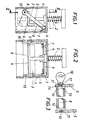
- the self-inking stamp has a housing-shaped lower part 1 which can be placed on the surface to be stamped, and a stamp insert 3 which is guided in a straight line and can be displaced toward the contact surface against the force of a spring 2 and which carries a pressure plate 4 or the like.
- a stamp insert 3 which is guided in a straight line and can be displaced toward the contact surface against the force of a spring 2 and which carries a pressure plate 4 or the like.
- two swivel arms 5 are arranged, which are connected to a rigid bracket by a transverse part 6 forming their swivel shaft.
- the pivot bearings of this bracket 5, 6 are formed by approximately half-shell-shaped lugs 7 of the housing wall of the lower part 1. In the vertical projection the contact surface, the pivot bearings or the half-shells 7 are arranged next to the stamp insert 3, as can be clearly seen in FIG. 1.
- the swivel arms 5 hold an inking roller 8 which, in the rest position of the stamp insert 3 drawn in solid lines in FIGS. 1 and 2, bears against the edge of the stamp insert 3 opposite the pivot bearing 7.
- the swivel arms 5 and the bracket 6 are or is under the action of a return spring 9, which tends to move the bracket upwards, i. H. to press the ink roller 8 against the pressure plate 4.
- the inking roller 8 rolls over the pressure plate 4 and finally evades the stamp insert 3 (dashed position according to FIGS. 1 and 2).
- the lower part 1 For mounting or ejecting the inking roller 8, the lower part 1 is provided in its side walls in the region of the pivoting movement path of the inking roller 8 with insertion or ejection holes 10.
- One of the two pivot levers 5 (the right one in FIGS. 2 and 3) has at its free end a bore 11 for receiving a bearing journal 12 of the inking roller 8, which has a widened head 13 that can be elastically compressed by slitting.
- the other (left) pivot lever 5 is provided with a bearing hole 14 corresponding to the ink roller size diameter, the ink roller 8 being mounted in the bearing hole 14 of the respective pivot lever 5 with a disk 16 which can also be rotated on a pin 15 with a slotted head.
- the inking roller 8 or the rotatable disk 16 is equipped with a handle attachment 18 connected to it via a predetermined breaking point 17.
Landscapes
- Inks, Pencil-Leads, Or Crayons (AREA)
- Inking, Control Or Cleaning Of Printing Machines (AREA)
Applications Claiming Priority (2)
| Application Number | Priority Date | Filing Date | Title |
|---|---|---|---|
| AT1022/90 | 1990-05-07 | ||
| AT102290A ATA102290A (de) | 1990-05-07 | 1990-05-07 | Selbstfaerbestempel |
Publications (2)
| Publication Number | Publication Date |
|---|---|
| EP0456631A1 true EP0456631A1 (fr) | 1991-11-13 |
| EP0456631B1 EP0456631B1 (fr) | 1994-03-09 |
Family
ID=3505038
Family Applications (1)
| Application Number | Title | Priority Date | Filing Date |
|---|---|---|---|
| EP19910890071 Expired - Lifetime EP0456631B1 (fr) | 1990-05-07 | 1991-04-09 | Timbre à encrage automatique |
Country Status (3)
| Country | Link |
|---|---|
| EP (1) | EP0456631B1 (fr) |
| AT (1) | ATA102290A (fr) |
| DE (1) | DE59101129D1 (fr) |
Cited By (1)
| Publication number | Priority date | Publication date | Assignee | Title |
|---|---|---|---|---|
| US5771799A (en) * | 1995-06-08 | 1998-06-30 | Makino; Kazunosuke | Ink roller device and numbering machine equipped with the ink roller device |
Citations (3)
| Publication number | Priority date | Publication date | Assignee | Title |
|---|---|---|---|---|
| GB322264A (en) * | 1928-09-18 | 1929-12-05 | Charles Sumner Du Belle | Inking means for hand stamp machines and other printing machines |
| GB398754A (en) * | 1933-03-29 | 1933-09-21 | Carl Otto Robert Ludewigs | Improvements in and relating to stamping devices |
| GB1029889A (en) * | 1962-03-12 | 1966-05-18 | Edmond Prosper Nestor Gerard | Improvements in or relating to printing stamps |
-
1990
- 1990-05-07 AT AT102290A patent/ATA102290A/de unknown
-
1991
- 1991-04-09 DE DE91890071T patent/DE59101129D1/de not_active Expired - Fee Related
- 1991-04-09 EP EP19910890071 patent/EP0456631B1/fr not_active Expired - Lifetime
Patent Citations (3)
| Publication number | Priority date | Publication date | Assignee | Title |
|---|---|---|---|---|
| GB322264A (en) * | 1928-09-18 | 1929-12-05 | Charles Sumner Du Belle | Inking means for hand stamp machines and other printing machines |
| GB398754A (en) * | 1933-03-29 | 1933-09-21 | Carl Otto Robert Ludewigs | Improvements in and relating to stamping devices |
| GB1029889A (en) * | 1962-03-12 | 1966-05-18 | Edmond Prosper Nestor Gerard | Improvements in or relating to printing stamps |
Cited By (1)
| Publication number | Priority date | Publication date | Assignee | Title |
|---|---|---|---|---|
| US5771799A (en) * | 1995-06-08 | 1998-06-30 | Makino; Kazunosuke | Ink roller device and numbering machine equipped with the ink roller device |
Also Published As
| Publication number | Publication date |
|---|---|
| EP0456631B1 (fr) | 1994-03-09 |
| DE59101129D1 (de) | 1994-04-14 |
| ATA102290A (de) | 1991-06-15 |
Similar Documents
| Publication | Publication Date | Title |
|---|---|---|
| DE69917184T2 (de) | Aufzeichnungsgerät | |
| DE2310573C3 (de) | Druckbleistift | |
| EP0567909B1 (fr) | Procédé pour appliquer un dispositif en creur à chambre fermée sur un rouleau encreur et dispositif pour sa mise en oeuvre | |
| DE60003780T2 (de) | Halter für den Kern einer Etikettenrolle | |
| DE4213660C2 (de) | Kurzfarbwerk für eine Rollenrotationsdruckmaschine | |
| DE3546322A1 (de) | Farbband-kassette und ladevorrichtung fuer diese farbband-kassette | |
| DE3131750C2 (de) | Zuführrollenvorrichtung für eine Schreibmaschine | |
| EP0567906B1 (fr) | Dispositif pour le réglage d'un porte-racle contre un cylindre donneur d'encre dans une machine d'impression rotative | |
| DE2220483C3 (de) | Mechanische Betätigungsvorrichtung für eine Innenbacken-Trommelbremse | |
| EP0456631B1 (fr) | Timbre à encrage automatique | |
| DE3413685C2 (fr) | ||
| DE2312268B2 (de) | Vorderbacken einer Auslöseskibindung | |
| DE10047455A1 (de) | Schraubvorrichtung für ein streifenförmiges Schraubenmagazin | |
| EP0035240B1 (fr) | Dispositif d'impression | |
| EP0287822A1 (fr) | Dispositif pour enlever des particules étrangères du cylindre porte-plaque d'une machine à imprimer offset | |
| DE3534664C2 (fr) | ||
| DE3220396C2 (de) | Tintenstrahldrucker | |
| DE2340980C2 (de) | Vorrichtung zum Befestigen von Druckplatten | |
| DE3202808C2 (de) | Skibremse | |
| DE3422794A1 (de) | Vorrichtung zum zufuehren von einzelblaettern zu einer bueromaschine | |
| DE9218053U1 (de) | Einrichtung zum Festklemmen und Anstellen eines Rakelbalkens an eine farbabgebende Walze einer Rollenrotationsdruckmaschine | |
| DE8915910U1 (de) | Papierhaltevorrichtung | |
| DE2824451C2 (de) | Handstanzgerät zum Ausklinken von Blechtafeln o.dgl. | |
| DE2604815C2 (de) | Punktdrucker für Mehrfachregistriergeräte nach dem Kompensationsverfahren | |
| AT392734B (de) | Skibremse |
Legal Events
| Date | Code | Title | Description |
|---|---|---|---|
| PUAI | Public reference made under article 153(3) epc to a published international application that has entered the european phase |
Free format text: ORIGINAL CODE: 0009012 |
|
| AK | Designated contracting states |
Kind code of ref document: A1 Designated state(s): DE GB IT NL |
|
| 17P | Request for examination filed |
Effective date: 19920504 |
|
| 17Q | First examination report despatched |
Effective date: 19930809 |
|
| GRAA | (expected) grant |
Free format text: ORIGINAL CODE: 0009210 |
|
| AK | Designated contracting states |
Kind code of ref document: B1 Designated state(s): DE GB IT NL |
|
| ITF | It: translation for a ep patent filed | ||
| REF | Corresponds to: |
Ref document number: 59101129 Country of ref document: DE Date of ref document: 19940414 |
|
| GBT | Gb: translation of ep patent filed (gb section 77(6)(a)/1977) |
Effective date: 19940325 |
|
| PLBE | No opposition filed within time limit |
Free format text: ORIGINAL CODE: 0009261 |
|
| STAA | Information on the status of an ep patent application or granted ep patent |
Free format text: STATUS: NO OPPOSITION FILED WITHIN TIME LIMIT |
|
| 26N | No opposition filed | ||
| PGFP | Annual fee paid to national office [announced via postgrant information from national office to epo] |
Ref country code: GB Payment date: 19960328 Year of fee payment: 6 |
|
| PGFP | Annual fee paid to national office [announced via postgrant information from national office to epo] |
Ref country code: DE Payment date: 19960426 Year of fee payment: 6 |
|
| PGFP | Annual fee paid to national office [announced via postgrant information from national office to epo] |
Ref country code: NL Payment date: 19960430 Year of fee payment: 6 |
|
| PG25 | Lapsed in a contracting state [announced via postgrant information from national office to epo] |
Ref country code: GB Effective date: 19970409 |
|
| PG25 | Lapsed in a contracting state [announced via postgrant information from national office to epo] |
Ref country code: NL Effective date: 19971101 |
|
| GBPC | Gb: european patent ceased through non-payment of renewal fee |
Effective date: 19970409 |
|
| PG25 | Lapsed in a contracting state [announced via postgrant information from national office to epo] |
Ref country code: DE Free format text: LAPSE BECAUSE OF NON-PAYMENT OF DUE FEES Effective date: 19980101 |
|
| NLV4 | Nl: lapsed or anulled due to non-payment of the annual fee |
Effective date: 19971101 |
|
| PG25 | Lapsed in a contracting state [announced via postgrant information from national office to epo] |
Ref country code: IT Free format text: LAPSE BECAUSE OF NON-PAYMENT OF DUE FEES;WARNING: LAPSES OF ITALIAN PATENTS WITH EFFECTIVE DATE BEFORE 2007 MAY HAVE OCCURRED AT ANY TIME BEFORE 2007. THE CORRECT EFFECTIVE DATE MAY BE DIFFERENT FROM THE ONE RECORDED. Effective date: 20050409 |