EP0456701B1 - Systeme et procede d'acces synchronise deterministe a un bus - Google Patents
Systeme et procede d'acces synchronise deterministe a un bus Download PDFInfo
- Publication number
- EP0456701B1 EP0456701B1 EP90902662A EP90902662A EP0456701B1 EP 0456701 B1 EP0456701 B1 EP 0456701B1 EP 90902662 A EP90902662 A EP 90902662A EP 90902662 A EP90902662 A EP 90902662A EP 0456701 B1 EP0456701 B1 EP 0456701B1
- Authority
- EP
- European Patent Office
- Prior art keywords
- node
- bus
- polling
- nodes
- reference signal
- Prior art date
- Legal status (The legal status is an assumption and is not a legal conclusion. Google has not performed a legal analysis and makes no representation as to the accuracy of the status listed.)
- Expired - Lifetime
Links
Images


Classifications
-
- H—ELECTRICITY
- H04—ELECTRIC COMMUNICATION TECHNIQUE
- H04L—TRANSMISSION OF DIGITAL INFORMATION, e.g. TELEGRAPHIC COMMUNICATION
- H04L12/00—Data switching networks
- H04L12/28—Data switching networks characterised by path configuration, e.g. LAN [Local Area Networks] or WAN [Wide Area Networks]
- H04L12/40—Bus networks
- H04L12/407—Bus networks with decentralised control
- H04L12/417—Bus networks with decentralised control with deterministic access, e.g. token passing
-
- H—ELECTRICITY
- H04—ELECTRIC COMMUNICATION TECHNIQUE
- H04L—TRANSMISSION OF DIGITAL INFORMATION, e.g. TELEGRAPHIC COMMUNICATION
- H04L12/00—Data switching networks
- H04L12/28—Data switching networks characterised by path configuration, e.g. LAN [Local Area Networks] or WAN [Wide Area Networks]
- H04L12/40—Bus networks
- H04L12/407—Bus networks with decentralised control
Definitions
- the present invention relates to an improved deterministic bus access method which is appropriate where a number of stations (or nodes) on a bus which wish to communicate, are located at a distance for example more than 5 metres apart from each other.
- the invention relates to the field of Local Area Networks (LANs).
- LANs Local Area Networks
- some centralised arbitration system can be used e.g. a central controller.
- the electrical signal propagation delay can limit the effectiveness (speed) of the access mechanism.
- constraints imposed on the speed of the access mechanism by the basic nature of a bus can be particularly severe (especially with short packet transmission times and physically long buses). These constraints are firstly that any signal transmitted on a bus is broadcast so that it is received by all stations connected to it and secondly, that the maximum time between a station sending a signal and another station receiving the signal is the end-to-end propagation time of the bus.
- CSMA/CD Collision Sense Multiple Access/Collision Detect
- the performance of another widely used method of access, token passing, is limited chiefly by the first consideration because here the token has to be directed to one node at a time by the addition of adequate address information (to the token).
- the time to transmit the token from one node to the next mode (in the logical ring) plus some allowance for internal node processing and node to node propagation times generally yields fairly lengthy node to node polling times (e.g. of approximately 50 uS in the case of a typical 5 Mbps carrier band implementation of the IEEE 802.4 token passing bus).
- the time for the token to circulate completely round the logical ring of such a network is therefore the node to node polling time multiplied by the number of network nodes: for a typical 30 node network this results in a token circulation time of about 1.5 ms (30 x 50 uS). This circulation time results in excessively long waiting time delays for short packets of data.
- MLMA Multi Level Multi Access
- the total time taken by the determinsitic methods is based on the fact that the duration of each bit of information in the access method must equal or exceed the end-to-end propagation time of the bus. (e.g. 5uS for a 1Km bus) so that all stations are aware of when each particular bit in the access protocol has been set.
- U.S. Patent No. 4,464,749 describes a bi-directional token flow system based on the use of virtual tokens for use on a bi-directional bus with a number of connected nodes - called BIUs (Bus Interface Units). Each packet contains a source address, a destination address, a cyclic redundancy check and frame delimiters in the normal way. The right of a BIU to transmit a data packet onto the bus is transferred from BIU to BIU by the passage of a virtual token. Ulug's invention uses a system of time delays to ensure that no two BIUs receive a token at the same time and thus only one BIU will have the right to place its information on the bus at any given instant, i.e. when it receives the virtual token.
- a second disadvantage is that the time delay used by each BIU is calculated from the physical address of the BIU.
- the physical addresses are unique 48 bit numbers allocated on a worldwide basis by the IEEE - rather than being present by switches on a local basis. It is therefore impractical to base a system of time delays on the physical addresses of the BIUs - because there is no ability to arrange for adjacent nodes to have sequential addresses - for instance if BIUs were replaced or added later to the network.
- U.S. Patent No. 4,701,911 describes another system for contention free access to a uni-directional bus with a number of connected BIUs.
- BIUs have one connection to a uni-directional receive bus and one connection to a uni-directional transmit bus.
- the downstream end of the transmit bus is coupled to (what Ulug defines as) the downstream end of the receive bus by an intelligent head end, in the normal way.
- the order of access of BIUs which wish to transmit a data packet onto the transmit bus is controlled by a system of "beep" signals, which are transmitted by each BIU after receipt of a start-up packet.
- the start-up packet is transmitted from the intelligent head end which also relays all signals from the transmit bus to the receive bus.
- the access system operates by each BIU counting the number of beeps received ahead of its principal beep. This is its order in the transmit queue, i.e. the station nearest the head end transmits first and so on.
- Ulug includes both a left sweep and a right sweep start-up packet.
- BIUs count the number of beeps they receive before their own principal beep to determine the transmission order and in the case of a left sweep they count the number of beeps after receipt of their principal beep.
- the BIU which receives no beeps after its principal beep transmits its data packet first.
- the object of this invention is to obviate or mitigate disadvantages associated with the basic broadcast nature of a bus as evidenced by the problems with the above existing methods.
- This is achieved by transmitting an access signal onto the bus and by locating a master polling node capable of generating a master timing reference signal or slot pulse at a suitable point on the bus, for instance at one end.
- the function of issuing the master timing signal can be carried out by a dedicated node with no other purpose or by a node which can also transmit messages. In each case the node carrying out these functions is henceforth referred to as the polling node.
- a method of providing timed deterministic access to a bus structure having a plurality of nodes coupled thereto comprising the steps of,
- the value of the time delays at each node are chosen so that transmission from a number of active nodes follows a set sequence.
- the polling node is disposed at the end of the bus. This arrangement provides the highest access performance.
- the time delay corresponds to the order of the physical location of each node on the bus structure from the master polling node.
- the time delay can be fixed at each node by modifying the time duration of the reference signal as it passes through each node.
- each node receives a reference signal it
- each node remains silent after it sets its first flag until it receives the next reference signal from the master polling node.
- each node remains silent on receipt of subsequent timing reference signals from the master polling node after it has transmitted its message and set its second flag.
- the method includes the step of detecting, at the master polling node, when transmission of a packet is complete before the next reference signal is issued.
- the master polling node detects when all nodes have set their second flags and are remaining silent and after a predetermined period issues a cycle start reference signal to reset the second flags of each node to permit all nodes to be able to start transmission on receipt of a subsequent timing reference signal.
- the operation of the nodes can be arranged such that second timing reference signal issued after a predetermined period of silence can reset the second flags of each node to permit all nodes to start transmission.
- the timer delay of each node is determined by the time between the start of the reference signal and the start of the packet transmission which is n.td where n is an integer representative of the node position from the master polling node and td is a small time delay.
- nodes are assigned time delays 2n.tp + td where n is an integral representation of the number of the node, tp is the maximum end-to-end propagation delay on the bus structure and td is a small time delay.
- the time delay can be varied for each node by varying the time duration of the reference signal received at the node wishing to transmit.
- the method includes associating each reference signal with a priority reservation field generated between the reference signal and the start of the packet being transmitted from a node, the priority reservation field being compared by each node with its own priority and a node being able to transmit onto the bus structure if its priority is greater or equal to a predetermined priority value, and the bus structure is silent.
- the master polling node when the master polling node is located at one end of the bus the master polling node generates a priority request signal followed by a priority invitation period to allow the nodes to set their priority fields, and these fields being circulated back to the master polling node which issues a further reference signal which allows the first upstream node having a priority greater than or equal to the priority and reservation field to transmit a packet during the current interval if the bus is silent.
- time delays of each node can be set manually or automatically.
- the master polling node sends a reference signal pattern to each node in turn, said reference signal pattern containing node address information for the particular node, and after a preset time the recipient node replies to the master polling node, whereupon the master polling node stores a value representative of the distance of the recipient node from the master polling node in its memory and allocates a unique value of time delay to each node using the network's communication facilities.
- the master polling node automatically reconfigures the priority of nodes coupled to the bus structure in response to the node request using the network's communication facilities.
- the method includes the step of equipping a number of nodes with polling facilities whereby on failure of upstream nodes the most operational upstream node automatically assumes the polling function.
- the system operates independent of the physical location of the polling node any other active node can assume the polling function.
- each node coupled to the bus structure is capable of issuing a reference signal after it has transmitted the end of its packet, wherein the master polling node passes the received signal back to its upstream output to allow several packets to co-exist on the uni-directional bus (assuming the electrical length of the bus is longer than the transmission time of a packet).
- a system for providing timed deterministic access to a bus structure having a plurality of nodes coupled thereto comprising,
- the master polling means is located at one end of the bus and the active node closest to the polling node transmits first.
- the polling node may be located anywhere on the bus structure and the increments between the time delays assigned to each node in this arrangement are conveniently made longer than twice the maximum propagation delay between the most remote ends on the bus structure.
- said time delay means is variable for each node to vary the time delay after which the node can transmit a packet.
- time delay means is fixed at each node, the time delay after which the node issues a packet being modified by lengthening the timing reference signal as it passes through each node.
- time delays of each node are manually or automatically resettable to a different value.
- system nodes are automatically reconfigurable to modify the value of the priority of nodes in response to node requests.
- the bus structure is selected from the group consisting of a bidirectional linear bus, a uni-directional linear bus, a star (hub) and a tree.
- the system includes means for generating a priority reservation field coupled to the master polling unit, and priority comparison means coupled to each node for comparing the priority of the reservation field with the priority of the node.
- the system may provide timed deterministic access to a uni-directional bus.
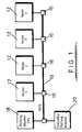
- Fig. 1 of the drawings depicts a bi-directional linear bus 10 coupled to nodes 12 via connectors 16 on the bus 10. It will be appreciated that a plurality of nodes are coupled to the bus but only four nodes 1 to 4 are shown in the interest of clarity.
- a monitor or master polling node 18 is located at one end of the linear bus 10. It will be appreciated that this master node 18 can also transmit data as well as controlling access to the bus 10 although only this function is described.
- One or more standby polling master nodes 20 are also located at the end of the bus 10 so that if master polling nodes 18 fails the standby node 20 can replace polling functions, as is well known in the art. It will be appreciated that these standby nodes may also be capable of data transmission.
- Each node 12 is coupled to a connector 16 via a bus transceiver (not shown in the interest of clarity).
- the system is arranged so that for polling functions uni-directional operation is achieved on a bi-directional linear bus by locating the polling node 18 at one end of the bus.
- a polling node located at an end issues a signal such as a pulse it propagates uni-directionally along the bus. Termination matched to the characteristic impedance of the bus will ensure a limited amplitude of reflection of signals from the remote end.
- a medium speed data rate i.e. (1 to 10 Mbps
- All nodes 12, coupled to the bus listen to the bus 10.
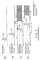
- the master polling node 18 monitors the bus and, when the bus is silent for a sufficient period, issues a timing reference signal or "slot" pulse 34 which is conveniently represented as a pulse of rectangular shape as seen in Fig. 2a.
- This signal (pulse) 34 propagates uni-directionally and is received by each node 12 after its release at a time corresponding to the product of the physical distance of the particular node from the master polling station 18 and the propagation rate of the medium.
- Each node 12 is equipped with a delay timer (not shown in the interest of clarity) which is set to a value n.td where n is the number of the node according to its physical position from node 18, and td a small delay, for example 0.5 uS per node.
- a time delay corresponding to the order of physical location of each node on the bus 10 from node 18 ensures that only one active node, namely that located closest to master polling node 18, can start transmission in any one slot pulse cycle. This is achieved by a mechanism shown in Fig. 2d.
- node n and node n+1 (eg node 2 and node 3) wish to transmit in a given slot pulse cycle, where a slot pulse cycle is the time between the issue of one slot pulse by the polling node and the next.
- node 2 is the upstream node (i.e. that nearer the polling node 18)
- it inspects the state of the bus at a time tp2 + 2.td. and finds that the bus is silent and starts to transmit.
- node 3 At time tp3 node 3 receives the slot pulse. It in turn examines the bus at a time 3.td after the slot pulse arrives at the node and finds it busy because of the packet being transmitted from node 2. It therefore waits until the next slot pulse is received before it can attempt to transmit.
- nodes which are physically close to node 18 and which discover later in the slot pulse cycle that they have traffic are prevented from transmitting once the current slot pulse of the current cycle has propagated past them.
- node 18 After transmission of a packet, node 18 detects that the bus 10 has gone silent and issues another slot pulse. Alternatively the downstream end of bus 10 can be connected back into the receiving circuits of master node 18.
- the polling master node 18 knows that within twice the end-to-end propagation delay of the bus plus M.td that no nodes wish to transmit (where M is the number of nodes connected to the bus excluding the polling nodes).
- the polling master node 18 When the polling master node 18 detects a silence extending beyond this period the node 18 realises that all active stations have been allowed access to the bus at least once. The polling node then transmits a pulse pattern called the "cycle start" pulse 40 as seen in Fig. 3.
- the cycle start pulse 40 ensures an orderly polling cycle for all the nodes. It causes all nodes 12 to reset their "transmit”flags and allows all nodes to start transmission on receipt of a slot pulse 34, subject to the above mentioned rules.
- the "cycle start” pulse 40 is followed by a series of slot pulses and this is repeated throughout the operation of the bus access method. It will be appreciated that the operation of the nodes can be modified such that a second slot pulse after a predetermined period of silence can perform the same function as the cycle start pulse. Such an arrangement has the advantage that a second signal pattern does not require to be generated or detected.
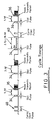
- FIG. 4 of the drawings depicts a tree 40 coupled to nodes 42. It will be appreciated that a plurality of nodes are coupled to the bus but only seven A to G are shown in the interest of clarity.
- a monitor or polling master node 44 is located at the "root" of the tree. The master node 44 can also transmit data as well as controlling access to the tree 40. Standby polling nodes can also be provisioned but are not shown in the interests of clarity.
- Figs. 5a-5c All nodes 42 coupled to the tree (bus) listen to the bus 40.
- the master polling node 44 monitors the bus and issues a "slot" pulse 46 conveniently of rectangular shape as shown in Fig. 5a when the bus is silent.
- This pulse 46 propagates along the tree 40 and is received by each node 42 at a time corresponding to the physical distance from the master polling node 44. It will be appreciated that at point R on the tree the slot pulse 46 will propagate simultaneously down the trunk 48 and down branch 50 of the tree to nodes C and D.
- L1 is the distance of point R from the master polling node
- L2 is the distance from point R to node D
- L3 is the distance from point R to node B.
- the propagation times corresponding to lengths L1, L2 and L3 are t1, t2 and t3 respectively.
- the slot pulses reach node D at a time t1 + t2 and node B in a time t1 + t3 as seen in Figs. 5b and 5c.
- a suitable value for the time delay for node B is t1 + 2t2 + t3 + (d+1).
- t d - (t1 + t3). 2t2 + (d+1) .t d and this is diagrammatically seen in Fig. 5c which is the time at which node n+1 (node B) would have started transmission.
- a cycle start pulse is also used to ensure an orderly polling cycle for all the nodes in the same way as achieved with the bidirectional bus and the cycle start pulse can be a pair of pulses as seen in Fig. 3 or other suitable signal pattern of pulses. Alternatively a second slot pulse after a predetermined period of silence can be used as heretofore described.
- FIG. 6 of the drawings is a schematic block diagram of a Hub (or star) bus configuration 58 having a polling system in accordance with further embodiment of the invention to provide deterministic access to the Hub bus.
- FIG. 6 of the drawings depicts a hub 60 coupled by star links 62 to five nodes 64 A to E.
- a monitor or polling master node 66 is connected to the hub 60 . It will be appreciated that this master node 66 can also transmit data as well as controlling access to the bus configuration although only this (polling) function is described.
- the master polling node 66 monitors the bus and issues a slot pulse of rectangular shape as described above when the bus is silent. This pulse simultaneously propagates along the star links to the nodes 64 A to E which are at a distance L1, L2, L3, L4 and L5 respectively from the Hub 60.
- the signal propagation times corresponding to L A to L E are t A to t E respectively.
- Each node will receive the slot pulse at times t h +t a , t h +t B , t h +t D etc. where t h is propagation time between the polling master 66 and the hub 60.
- the time for the slot pulse to reach Node A is t h +tA.
- the earliest time that node A can start transmission is t h +t A +t d where td is the timer delay at each node.
- td is the timer delay at each node.
- the B node timer delay must be greater than the difference between the arrival time of the slot pulse and a packet from node A.
- the value of the timer delay at node B is chosen as 2t A + 2t d .
- Fig. 7 is a schematic block diagram of a uni-directional bus 70 to which a series of four nodes 72 is connected via repeaters 74.
- a polling master node 76 is located with its transmitter at the most upstream end of the bus.
- a standby node can be provisioned but this is not shown in the interests of clarity. It will be understood that each node connected to the bus 70 can listen to the upstream state of the bus by a link 78A to 78D and transmit onto the bus over the same link or an adjacent link 78A to 78D.
- Links 80A to 80D allow the respective nodes 72A to 72D to listen to the downstream state of the bus to be able to receive messages transmitted on the upstream part of the bus by links 78 A to D.
- the arrangement shown in Fig. 7 can be used with different value timer delays for each node as described above to determine the transmission times for each node.
- an alternative arrangement of the uni-directional bus system is to incorporate fixed timer delays within the nodes 72A to 72D.
- the system uses a slot pulse and cycle start pulse pattern (or two adjacent slot pulses) in the same manner as described above.
- Fig. 8 is a schematic block diagram of part of a node 72A with a timer delay connected to the bus 70.
- the fixed delay is the same for all nodes.
- the node is coupled to the repeater 74 which includes an amplifier 82 in series with a delay element 84 and the bus 70 is also coupled by link 86 to a slot pulse detection circuit 88 in the node which is connected to a node transmission buffer 90.
- a changeover switch 92 is connected between bus 70 and the outputs of the delay circuit 84 and the node transmission buffer 90.
- the changeover switch 92 is also coupled to the logic circuit 88 by a control conductor 94 for controlling switch operation as will be described.
- all signals on the bus 70 pass through the repeater amplifier 82 which includes delay element 84 and change over switch 92. This allows the node's upstream packet detection logic 88 to determine whether a packet is arriving from an upstream node before a decision has to be made on whether to initiate a transmission from the transmission buffer 90 or whether the network is already transmitting an upstream packet. If the bus is silent and the node wishes to transmit the changeover switch 92 is connected to the transmission buffer 90.
- a control signal from logic circuit 88 on conductor 94 causes the changeover switch to connect the output of the delay element 94 to the downstream bus 70. If the medium is silent the control signal causes the output of the node transmission buffer 90 to be connected to the downstream bus.
- uni-directional bus system allows the same fixed timer delays to be incorporated at all of the nodes 72a to 72d.
- the system uses a slot pulse and cycle start pulse (or two adjacent slot pulses) in the same manner as described above.
- Fig. 9 depicts the operation of an alternative arrangement to that of Fig. 8 to determine node access in the bus structure shown in Fig. 7 where the nodes 72a to 72d each contain a circuit means to extending the length of the slot pulse by a fixed amount, say t w , as it passes through each node in turn.
- t w a fixed amount
- a node wishing to transmit a packet does so after a fixed time delay t f reckoned from the back edge 89 of the slot pulse i.e. timing reference signal 87.
- a downstream node wishing to transmit inspects the upstream state of the bus t f after the extended edge 89 of the slot pulse 87.
- node n and node n+1 (eg node B and node C wish to transmit in a given slot pulse cycle, where a slot pulse cycle is the time between the issue of one slot pulse and the next, then because node 2 is the upstream node it inspects the state of the bus at a time t s + 2.t w +t f after the start of the slot pulse and finds it silent and starts to transmit.
- Node 3 wishes to transmit and examines the state of the bus t s + 3.t w after the start of the slot pulse. It finds the bus busy at that time and sets its "next slot" flag and awaits receipt of the next slot pulse.
- nodes 72A to 72D can be equipped with a circuit for detecting that the slot pulse length has been increased from t s to t s + t w (not shown for the sake of clarity).
- the first upstream node with a packet to transmit determines that the width of the slot pulse is t w and lengthens it to t s + t w and transmits its packet.
- the cycle start pulse (or adjacent slot pulses) arrangement is operated in a manner similar to that described above.
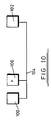
- Fig. 10 depicts nodes 100 and 102 connected to bus 104.
- Polling node 106 is also connected to bus 104 very close to node 100.
- Node 102 is located very close to the remote end of the bus. Since node 100 is very close to the polling node and node 102 is as remote from the polling node as is possible on the bus it would be natural to choose time delays which would allow node 100 to transmit before node 102. If we assign time delays to node 102 that allows it to transmit before node 100 then we have assigned time delays to the nodes which provide an order of transmission of the two nodes which is independent both of the physical position of either node on the bus and of the polling node.
- node 102 If node 102 is now moved closer to the polling node it will transmit earlier and thus provide a greater time safety margin in preventing node 100 transmitting. Also if node 100 is moved further from the polling node it will receive the slot pulse later (and given the same time delay) will transmit later (again increasing the safety margin).
- This logic can be expanded in a bus structure to cover a multiplicity of nodes. Additionally if the location of the polling node n is further from node 100 and closer to node 102 then node 102 will transmit earlier, and node 100 will transmit later. This shows that the physical location of the nodes are unimportant when these time delays are assigned to nodes 100, 102 and the polling node.
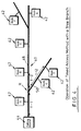
- Fig. 11 of the drawings depicts a tree topology network with the polling node disposed on the branch of the tree.
- this embodiment depicts nodes a to g connected to the tree structure 108.
- the longest end to end propagation time delay on the tree (tp) is from the end of the branch containing nodes c and d to the end of the branch containing node f. Because the branch containing nodes c and d is longer than the branch containing node a and the branch containing node f is longer than the branch containing node g.
- Polling master node 110 is connected to the branch containing node d very close to the end of the branch as shown in Fig. 11. Node f is located very close to the end of its branch. It will therefore be appreciated that the propagation delay between polling node p and node d is negligible and the propagation delay between nodes p and node f is tp.
- node d is very close to the polling node and node f is as remote from the polling node as is possible on the tree it would be natural to choose time delays which would allow node d to transmit before node f. If we assign time delays to node f that allows it to transmit before node d then we have assigned time delays to the nodes which are independent of the physical position of either node on the bus.
- Allocation of the following time delays allows node f to transmit before node d.
- node f If node f is now moved closer to the polling node it will transmit earlier and thus provide a greater safety margin in preventing node d transmitting. Also if node d is moved further from the polling node it will receive the slot pulse later (and given the same node timer delay) will transmit later (again increasing the safety margin).
- the master polling node 110 may be located anywhere on the tree structure and the time delays at individual nodes made independent of their physical location on the bus structure.
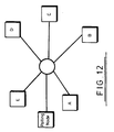
- a star or hub bus configuration is shown in Fig. 12.
- the master polling node may be located on any of the star links and the time delays at individual nodes made independent of their physical location on the hub bus.
- timer values assigned to successive nodes are incremented (from one node to another) by more than twice the maximum propagation delay (tp) on the longest star link of the hub bus.
- tp maximum propagation delay
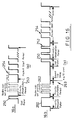
- FIG. 13 of the drawings depicts an Ethernet bus 200 coupled to a Real-Time (RT) node 202 and a Non Real Time (NRT) node 204 via TAPS 206 on the bus 200.
- RT Real-Time
- NRT Non Real Time
- a monitor or polling master node 208 is located at one end of the linear bus 200. Although node 208 may also transmit data only its polling function will be described here.
- One or more standby polling master nodes 210 are also located at the end of the bus 200 so that if master polling node 208 fails the standby node 210 can assume the polling functions. (Alternatively node time delays can be assigned so that physical location of the nodes including the polling node is unimportant).
- Each RT node 202 is coupled to a TAP unit 206 via a standard Ethernet transceiver 212.
- the RT node 202 includes a standard Ethernet controller 214 and control logic 216 for implementing the method of deterministic access.
- the NRT node 204 includes a standard Ethernet node 218, for example, a standard computer, such as a Digital Equipment Corporation VAX (trademark) which includes a standard Ethernet controller 220 and standard Ethernet hardware and software unit 222.
- the node 204 is coupled via an interface access unit (IAU) 226, located in the drop cable (or at an equivalent circuit point with Cheapernet) as disclosed in UK Patent No. 2187917B, and transceiver 212 to TAP 206.
- IAU interface access unit
- the network When the network is in NRT mode, if an RT node becomes active it injects a special signal pattern onto the Ethernet bus once it detects silence on the bus after the end of a packet.
- the special signal pattern can be on collision signal 227 extended beyond its maximum time limit (e.g. to 100uS.).
- maximum time limit e.g. 100uS.
- any other signal pattern (which can be recognised as non standard by the IAUs) can also be used.
- the IAUs (226) thus detect the presence of the non standard signal pattern and conveniently generates a carrier signal and transmit a short jam signal to their connected nodes 204 but alternatively can use other signalling methods to prevent transmission from the NRT nodes (204) connected to them the network effectively enters a real-time mode and the polling master 208 issues a slot pulse 229 along the bus as disclosed above.
- Operation of the basic timed access method for the RT nodes 202 is as previously described above for the bidirectional linear bus tree structure or hub structure with the exception that when no response is received from the slot pulse 231 immediately following a cycle start pulse 233 the network returns to NRT mode.This is best seen in the cycle timing diagram in Fig. 14.
- timed access protocol can be modified to include prioritised access by nodes and this is described in detail below with reference to Fig. 15 which is a schematic block diagram of a linear bus coupled to a polling system in accordance with a further embodiment of the invention to provide prioritised deterministic access to the bus, and Figs. 16a and 16b which are waveform diagrams depicting propagation of a slot pulse with an accompanying priority reservation period during which the priority reservation field can be set.
- Fig. 15 of the drawings depicts a bus 240 coupled to four nodes 242A to 242D. It will be appreciated that a plurality of nodes can be coupled but only the four nodes are shown in the interest of clarity.
- the transmitted output of the master or polling node 248 is located at one end of the bus 240 and the receiving circuits are located at the other end of the bus.
- the primary purpose of the master node is to control access to the bus rather than transmit data.
- Standby master nodes (not shown) can be provided as described above.
- Figs. 15 and 16a All nodes 242 coupled listen to the bus.
- the master polling node 248 monitors the bus and issues a timing reference signal which we shall conveniently represent diagramatically as being of "slot" pulse 250 rectangular shape as seen in Fig. 16a, (for a network data transmission rate of 1 to 10 Mbps) when the bus is silent.
- a priority reservation field 252 contained within priority reservation period 253 is included after the slot pulse 250 and before the Node Packet Start period (NPS) 254.
- NPS Node Packet Start period
- the nodes 242 compare their priority with the present state of the priority reservation field and if their priority is higher set their priority by transmitting 3 priority reservation bits 252 onto the bus 240 to allow eight distinct levels of priority. It will be appreciated that the bus 240 may already be transmitting a packet from a lower priority upstream node.
- the slot pulse 250 is followed by the priority reservation field which after passing node D contains the priority of the highest priority node wishing access to the bus 240, propagates back to the receiving circuits Rx on the master polling node 248.
- the master polling node 248 then issues the next slot pulse with the priority field 252 set to the highest priority encountered on the previous slot pulse cycle.
- each node compares the state of the priority reservation field with its own priority and if it has an equal or higher priority and the bus is silent at the time it wishes to start packet transmission then it can do so.
- Various algorithms can be employed to reduce the value of the priority reservation field when their is no response to a slot pulse at a particular priority level. In the first algorithm the priority level on release of the next slot pulse is reduced by one. In the second it is divided by two (ie right shifted one place). In the third it is set to zero.
- Fig. 16b depicts an arrangement to avoid these waiting time delays by introducing a priority request pulse 260.
- nodes 242A to 242D set their priority fields 262 which circulate back to the master polling station 248. This station then issues a normal slot pulse 250 which allows the first upstream node with priority equal or greater than the priority reservation field 252 to transmit a packet 254 during the current slot pulse cycle.
- this sequence of bits may consist of a whole or a part of a standard (or non-standard) Ethernet packet and may conform or not to the standard Ethernet signal levels and timings and in decoding the sequence of bits the receivers may group the received sequence of bits into bytes (or other suitable groupings).
- one sequence of bits, which can be uniquely interpreted by the receiving nodes, may be used as the slot pulse and another unique pattern may be used as the cycle start pulse and as priority request (invitation) or set pulses(s).
- the value of the timers in the various nodes can be set manually on the basis of the order of the node from the polling node or automatically.
- the polling node sends a unique "timer set" signal pattern to each of the receiving nodes in turn possibly using another medium access protocol to establish connections such as CSMA/CD.
- the unique pattern contains address information so that it can be addressed to an individual node.
- the recipient node replies after a fixed time interval.
- the polling node notes the delays involved between the transmission of the "timer set" pattern and receipt of the reply and stores value in the memory of the polling master station. This value is a unique measure of the distance of the particular node from the polling master station.
- the master polling node then allocates a unique value of timer delay to each node using the network's communication facilities.
- each node With uni-directional buses which can support several packets within the end-to-end propagation time of the bus, each node is equipped with the capability of issuing slot pulses after it has transmitted the end of its packet. In this arrangement the master polling node passes received slot pulses back to its upstream output. This arrangement allows several packet to co-exist on the bus and gives advantages analogous to multiple token operation.
- the polling master contains facilities which provide for recovery from lost slot and/or cycle start pulses. Also more than eight levels of priority can be provided depending on requirements of the system by increasing the number of priority reservation bits.
- Advantages of the invention are; there is provided a method of providing deterministic prioritised access to a bus which can have connected to it a plurality of nodes with different priorities and which is relatively inexpensive and straightforward to implement. It provides deterministic timed access without the need to maintain a logical ring (map) in all nodes and allows nodes to leave and rejoin the network without the need for software reconfiguration.
- the method provides simplified access to all nodes and offers substantially reduced access time per node when compared with existing methods particularly when priorised features are employed.
- the improved bus access method of this invention offers considerable advantages in performance over the widely used shared bus access methods such as CSMA/CD, central polling and token passing.
Landscapes
- Engineering & Computer Science (AREA)
- Computer Networks & Wireless Communication (AREA)
- Signal Processing (AREA)
- Small-Scale Networks (AREA)
- Bus Control (AREA)
- Medicines Containing Antibodies Or Antigens For Use As Internal Diagnostic Agents (AREA)
Claims (30)
- Procédé permettant d'assurer un accès déterministe cadencé à une structure de bus comportant une pluralité de noeuds qui lui sont couplés, ledit procédé comprenant les étapes de:a) disposition d'au moins un noeud d'interrogation qui joue le rôle de noeud d'interrogation maître permettant de générer un signal d'interrogation en un point approprié sur la structure de bus;b) génération d'un signal de référence de cadencement qui est indépendant de l'activité de transmission de données depuis ledit noeud d'interrogation maître afin d'inviter la totalité de l'activité du réseau sur la structure de bus après une période de silence, la période de silence variant en fonction de l'activité précédente sur la structure de bus;c) allocation à chaque noeud couplé à la structure de bus d'un retard temporel prédéterminé calculé indépendamment de l'adresse des données du noeud et fixé avant le début d'un fonctionnement normal du réseau, lequel détermine l'ordre de transmission si le noeud est actif;d) détection du signal de référence de cadencement généré au niveau de chaque noeud en tant que signal qui se déplace le long de la structure de bus, ledit signal de référence de cadencement étant utilisé par chacun des noeuds afin de commander son activité de transmission sur la structure de bus; ete) génération d'une transmission sur la structure de bus depuis un noeud actif qui présente la valeur la plus faible de la somme du retard temporel prédéterminé et du temps auquel le signal de référence de cadencement atteint le noeud si le bus est silencieux à cet instant.
- Procédé selon la revendication 1, dans lequel ledit au moins un noeud d'interrogation est disposé au niveau de l'extrémité du bus.
- Procédé selon la revendication 2, dans lequel, lorsque le noeud d'interrogation est au niveau de l'extrémité du bus, le retard temporel au niveau de chaque noeud correspond a l'ordre de l'emplacement physique de chaque noeud sur la structure de bus en partant du noeud d'interrogation maître.
- Procédé selon la revendication 2, dans lequel le retard temporel est fixé au niveau de chaque noeud en modifiant la durée temporelle du signal de référence lorsqu'il traverse chaque noeud.
- Procédé selon l'une quelconque des revendications précédentes, dans lequel, lorsque chaque noeud reçoit un signal de référence, il:a) établit un premier indicateur s'il n'a pas de message à transmettre; ou ilb) établit un second indicateur s'il a un message à transmettre et si l'état du bus lui permet de transmettre une information sur la structure de bus après son retard prédéterminé.
- Procédé selon la revendication 5, dans lequel chaque noeud reste silencieux après qu'il établit son premier indicateur jusqu'à ce qu'il reçoive le signal de référence suivant depuis le noeud d'interrogation maître.
- Procédé selon la revendication 5 ou 6, dans lequel chaque noeud reste silencieux lors de la réception de signaux de référence de cadencement ultérieurs en provenance du noeud d'interrogation maître après qu'il a transmis son message et qu'il a établi son second indicateur.
- Procédé selon l'une quelconque des revendications précédentes, dans lequel le procédé inclut l'étape de détection, au niveau du noeud d'interrogation maître, de l'instant où la transmission d'un paquet est terminée avant que le signal de référence suivant ne soit délivré.
- Procédé selon l'une quelconque des revendications 5 à 8, dans lequel le noeud d'interrogation maître détecte l'instant où tous les noeuds ont établi leurs seconds indicateurs et où ils restent silencieux et après une période prédéterminée, délivre un signal de référence de début de cycle afin de remettre à l'état initial les seconds indicateurs de chaque noeud afin de permettre à tous les noeuds de pouvoir démarrer une transmission lors de la réception d'un signal de référence de cadencement ultérieur.
- Procédé selon l'une quelconque des revendications 5 à 8, dans lequel le fonctionnement des noeuds peut être agencé de telle sorte qu'une seconde impulsion de fenêtre temporelle ou qu'un second signal de référence de cadencement délivré après une période de silence prédéterminée permette de remettre à l'état initial les seconds indicateurs de chaque noeud afin de permettre à tous les noeuds de démarrer une transmission.
- Procédé selon l'une quelconque des revendications 2 à 10, dans lequel, lorsqu'une interrogation s'effectue au niveau d'une extrémité du bus, le retard de minuterie de chaque noeud est déterminé par le temps entre le début du signal de référence et le début de la transmission de paquet qui vaut n.td où n est un entier représentatif de la position du noeud par rapport au noeud d'interrogation maître et td est un retard temporel faible.
- Procédé selon l'une quelconque des revendications 2 à 10, dans lequel, lorsque le système est configuré de telle sorte que l'emplacement du noeud d'interrogation et des autres noeuds n'a pas d'importance. alors des noeuds se voient assigner des retards temporels de 2n.tp + td où n est une représentation entière du numéro du noeud, tp est le retard de propagation de bout-en-bout maximum sur la structure de bus et td est un retard temporel faible.
- Procédé selon l'une quelconque des revendications 2 à 4, dans lequel, lorsque le noeud d'interrogation est situé au niveau d'une extrémité de la structure de bus, le procédé inclut l'association à chaque signal de référence d'une zone de réservation de priorité générée entre le signal de référence et le début du paquet qui est transmis depuis un noeud, la zone de réservation de priorité étant comparée par chaque noeud à sa propre priorité et un noeud pouvant transmettre sur la structure de bus si sa priorité est supérieure ou égale à une valeur de priorité prédéterminée, et la structure de bus est silencieuse.
- Procédé selon la revendication 13, dans lequel, lorsque le noeud d'interrogation maître est situé au niveau d'une extrémité du bus, le noeud d'interrogation maître génère un signal de requête de priorité qui est suivi par une période d'invitation de priorité pour permettre aux noeuds d'établir leurs zones de priorité et ces zones sont mises en circulation en retour jusqu'au noeud d'interrogation maître qui délivre un signal de référence supplémentaire qui permet au premier noeud amont présentant une priorité supérieure ou égale a la priorité et une zone de réservation de transmettre un paquet pendant l'intervalle courant si le bus est silencieux.
- Procédé selon l'une quelconque des revendications précédentes, dans lequel également les retards temporels de chaque noeud peuvent être établis manuellement ou automatiquement.
- Procédé selon la revendication 15, dans lequel, lors de l'établissement automatique, le noeud d'interrogation maître envoie un motif de signal de référence à chaque noeud tour-à-tour, ledit motif de signal de référence contenant une information d'adresse de noeud pour le noeud particulier, et après un temps pré-établi, le noeud destinataire répond au noeud d'interrogation maître, suite à quoi le noeud d'interrogation maître stocke une valeur représentative de la distance séparant le noeud destinataire et le noeud d'interrogation martre dans sa mémoire et alloue une unique valeur de retard temporel à chaque noeud en utilisant les équipements de communication du réseau.
- Procédé selon l'une quelconque des revendications précédentes, dans lequel le noeud d'interrogation maître reconfigure automatiquement la priorité des noeuds couplés à la structure de bus en réponse à la requête de noeud en utilisant les équipements de communication du réseau.
- Procédé selon l'une quelconque des revendications précédentes, dans lequel le procédé inclut l'étape consistant à munir un certain nombre de noeuds d'équipements d'interrogation et ainsi, lors d'une défaillance de noeuds amont, le noeud amont le plus opérationnel assure automatiquement la fonction d'interrogation.
- Procédé selon l'une quelconque des revendications 1 à 17, dans lequel, dans l'agencement dans lequel le système fonctionne indépendamment de l'emplacement physique du noeud d'interrogation, un quelconque autre noeud actif peut assurer la fonction d'interrogation.
- Procédé selon l'une quelconque des revendications précédentes, dans lequel, lorsque la structure de bus est un bus unidirectionnel, chaque noeud couplé à la structure de bus peut délivrer un signal de référence après qu'il a transmis la fin de son paquet, dans lequel le noeud d'interrogation maître passe un signal reçu en retour sur sa sortie amont pour permettre à plusieurs paquets de coexister sur le bus unidirectionnel si l'on suppose que la longueur électrique du bus est supérieure au temps de transmission d'un paquet.
- Système permettant d'assurer un accès déterministe cadencé à une structure de bus comportant une pluralité de noeuds qui lui sont couplés,
ledit système comprenant:a) au moins un moyen d'interrogation maître (18; 44; 66; 76) couplé à la structure de bus (10; 40; 62; 70) en un emplacement approprié pour générer un signal de référence de cadencement (34; 46; 84) qui est indépendant de l'activité de transmission de données sur ladite structure de bus afin d'initier la totalité de l'activité du réseau sur la structure de bus après une période de silence, la période de silence variant conformément à une activité précédente du réseau sur la structure de bus;b) un moyen de détection de signal de référence de cadencement (88) couplé à chaque noeud (12; 42; 64; 72) pour détecter ledit signal de référence (34; 46; 84) lorsqu'il passe ledit noeud, chaque noeud couplé à la structure de bus comportant un moyen de stockage (84) permettant de stocker un retard temporel prédéterminé calculé de façon indépendante de l'adresse de données et fixé avant le début d'un fonctionnement normal du réseau. ledit signal de référence de cadencement (34; 46; 84) étant utilisé par chacun des noeuds afin de commander son activité de transmission sur la structure de bus; etc) un moyen de surveillance d'activité de bus (88) associé à chaque noeud pour surveiller l'activité de la structure de bus, l'agencement étant tel qu'une transmission est générée sur la structure de bus depuis un noeud actif dont le retard temporel lui garantit l'opportunité de transmettre en premier un paquet sur ladite structure de bus un temps prédéterminé après que le signal de référence a été reçu par ledit moyen de détection de signal de référence de cadencement si le bus est silencieux à cet instant. - Système selon la revendication 21, dans lequel le moyen d'interrogation maître (18; 44; 76) est situé au niveau d'une extrémité du bus et le noeud actif le plus proche du noeud d'interrogation transmet en premier.
- Système selon la revendication 21, dans lequel le noeud d'interrogation (106; 110) est situé n'importe où sur la structure de bus et les incréments entre les retards temporels assignés à chaque noeud dans cet agencement sont rendus commodément plus longs que deux fois le retard de propagation maximum entre les extrémités les plus à distance sur la structure de bus.
- Système selon l'une quelconque des revendications 21 à 23, dans lequel également ledit moyen de retard temporel (84) est variable pour chaque noeud afin de faire varier le retard temporel après lequel le noeud peut transmettre un paquet.
- Système selon l'une quelconque des revendications 21 à 23, dans lequel ledit moyen de retard temporel (84) est fixé au niveau de chaque noeud (72), le retard temporel après lequel le noeud (72) délivre un paquet étant modifié en rallongeant le signal de référence de cadencement (87) lorsqu'il traverse chaque noeud (72).
- Système selon l'une quelconque des revendications 21 à 25, dans lequel la structure de bus est choisie parmi le groupe comprenant un bus linéaire bidirectionnel, un bus linéaire unidirectionnel, une étoile (connexion) et un arbre.
- Système selon l'une quelconque des revendications 21 à 26, dans lequel également le système inclut un moyen permettant de générer une zone de réservation de priorité couplée à l'unité d'interrogation maître, et un moyen de comparaison de priorité couplé à chaque noeud pour comparer la priorité de la zone de réservation a la priorité du noeud.
- Système selon l'une quelconque des revendications 21 à 27, dans lequel les retards temporels de chaque noeud peuvent être établis manuellement ou automatiquement à une valeur différente.
- Système selon la revendication 28, dans lequel les noeuds du système peuvent être reconfigurés automatiquement afin de modifier la valeur de la priorité des noeuds en réponse à des requêtes de noeud.
- Système selon l'une quelconque des revendications 21, 22 ou 25, dans lequel la structure de bus est un bus unidirectionnel (70).
Applications Claiming Priority (3)
| Application Number | Priority Date | Filing Date | Title |
|---|---|---|---|
| GB898902276A GB8902276D0 (en) | 1989-02-02 | 1989-02-02 | Improved deterministic timed bus access method |
| GB8902276 | 1989-02-02 | ||
| PCT/GB1990/000147 WO1990009068A1 (fr) | 1989-02-02 | 1990-02-01 | Procede ameliore d'acces synchronise deterministe a un bus |
Publications (2)
| Publication Number | Publication Date |
|---|---|
| EP0456701A1 EP0456701A1 (fr) | 1991-11-21 |
| EP0456701B1 true EP0456701B1 (fr) | 1995-04-26 |
Family
ID=10650997
Family Applications (1)
| Application Number | Title | Priority Date | Filing Date |
|---|---|---|---|
| EP90902662A Expired - Lifetime EP0456701B1 (fr) | 1989-02-02 | 1990-02-01 | Systeme et procede d'acces synchronise deterministe a un bus |
Country Status (5)
| Country | Link |
|---|---|
| EP (1) | EP0456701B1 (fr) |
| AT (1) | ATE121890T1 (fr) |
| DE (1) | DE69018971T2 (fr) |
| GB (1) | GB8902276D0 (fr) |
| WO (1) | WO1990009068A1 (fr) |
Families Citing this family (4)
| Publication number | Priority date | Publication date | Assignee | Title |
|---|---|---|---|---|
| JP2636534B2 (ja) * | 1991-03-22 | 1997-07-30 | 三菱電機株式会社 | 通信システム |
| GB9425860D0 (en) * | 1994-12-21 | 1995-02-22 | Galaxy Lans Ltd | Timed packet transmission method |
| CN102843266A (zh) * | 2011-06-22 | 2012-12-26 | 比亚迪股份有限公司 | 一种can网络数据发送方法 |
| EP4142222B1 (fr) * | 2020-04-30 | 2025-10-29 | KONE Corporation | Détermination d'une séquence de noeuds de bus dans un bus de communication multipoints |
Family Cites Families (2)
| Publication number | Priority date | Publication date | Assignee | Title |
|---|---|---|---|---|
| US4464749A (en) * | 1982-02-24 | 1984-08-07 | General Electric Company | Bi-directional token flow system |
| US4701911A (en) * | 1986-09-15 | 1987-10-20 | General Electric Company | Media accessing apparatus and method for communication system |
-
1989
- 1989-02-02 GB GB898902276A patent/GB8902276D0/en active Pending
-
1990
- 1990-02-01 DE DE69018971T patent/DE69018971T2/de not_active Expired - Fee Related
- 1990-02-01 AT AT90902662T patent/ATE121890T1/de not_active IP Right Cessation
- 1990-02-01 WO PCT/GB1990/000147 patent/WO1990009068A1/fr not_active Ceased
- 1990-02-01 EP EP90902662A patent/EP0456701B1/fr not_active Expired - Lifetime
Also Published As
| Publication number | Publication date |
|---|---|
| EP0456701A1 (fr) | 1991-11-21 |
| DE69018971D1 (de) | 1995-06-01 |
| GB8902276D0 (en) | 1989-03-22 |
| WO1990009068A1 (fr) | 1990-08-09 |
| ATE121890T1 (de) | 1995-05-15 |
| DE69018971T2 (de) | 1995-12-21 |
Similar Documents
| Publication | Publication Date | Title |
|---|---|---|
| US5434861A (en) | Deterministic timed bus access method | |
| EP0124381B1 (fr) | Système de transmission de données du type "accès par compétition" | |
| EP0029502B1 (fr) | Procédé de transmission de données entre les portes d'un système de communication comprenant un réseau de noeuds interconnectés et un système de communication comprenant un réseau de noeuds interconnectés et une unité de noeud pour l'utilisation dans un procédé ou système comme mentionné ci-dessus | |
| US6292493B1 (en) | Method and apparatus for detecting collisions on and controlling access to a transmission channel | |
| EP0179550B1 (fr) | Réseau étoile commandé | |
| EP0122765B1 (fr) | Protocole de réseau pour intégrer le trafic synchrone et asynchrone sur un bus de série commun | |
| US4495617A (en) | Signal generation and synchronizing circuit for a decentralized ring network | |
| US5802061A (en) | Method and apparatus for network access control with implicit ranging and dynamically assigned time slots | |
| JPH0831870B2 (ja) | Csma/cdを使用する光学的な受動スターローカルエリアネットワークのための衝突検出方法及び装置 | |
| US5018139A (en) | Communication network between user equipment | |
| US4631718A (en) | Method and device for synchronization of system timing | |
| GB2117939A (en) | Data communication network and method of communication | |
| CA1223370A (fr) | Methode et dispositif de detection de paquets de donnees | |
| US4813012A (en) | Terminal access protocol circuit for optical fiber star network | |
| US4547879A (en) | Digital data transmission process and installation | |
| JPH04213251A (ja) | 通信システム | |
| Wheels | Process control communications: Token bus, CSMA/CD, or token ring? | |
| EP0374683A2 (fr) | Méthode de concurrence pour réseaux de communication | |
| US4710918A (en) | Composite data transmission system | |
| EP0456701B1 (fr) | Systeme et procede d'acces synchronise deterministe a un bus | |
| US4538261A (en) | Channel access system | |
| Ulug et al. | Bidirectional token flow system | |
| US4815070A (en) | Node apparatus for communication network having multi-conjunction architecture | |
| US4843605A (en) | Node apparatus for communication network having multi-conjunction architecture | |
| GB2218599A (en) | Local access network signel regenerator |
Legal Events
| Date | Code | Title | Description |
|---|---|---|---|
| PUAI | Public reference made under article 153(3) epc to a published international application that has entered the european phase |
Free format text: ORIGINAL CODE: 0009012 |
|
| 17P | Request for examination filed |
Effective date: 19910724 |
|
| AK | Designated contracting states |
Kind code of ref document: A1 Designated state(s): AT BE CH DE DK ES FR GB IT LI LU NL SE |
|
| 17Q | First examination report despatched |
Effective date: 19930920 |
|
| GRAA | (expected) grant |
Free format text: ORIGINAL CODE: 0009210 |
|
| AK | Designated contracting states |
Kind code of ref document: B1 Designated state(s): AT BE CH DE DK ES FR GB IT LI LU NL SE |
|
| PG25 | Lapsed in a contracting state [announced via postgrant information from national office to epo] |
Ref country code: IT Free format text: LAPSE BECAUSE OF FAILURE TO SUBMIT A TRANSLATION OF THE DESCRIPTION OR TO PAY THE FEE WITHIN THE PRE;WARNING: LAPSES OF ITALIAN PATENTS WITH EFFECTIVE DATE BEFORE 2007 MAY HAVE OCCURRED AT ANY TIME BEFORE 2007. THE CORRECT EFFECTIVE DATE MAY BE DIFFERENT FROM THE ONE RECORDED.SCRIBED TIME-LIMIT Effective date: 19950426 Ref country code: AT Effective date: 19950426 Ref country code: LI Effective date: 19950426 Ref country code: ES Free format text: THE PATENT HAS BEEN ANNULLED BY A DECISION OF A NATIONAL AUTHORITY Effective date: 19950426 Ref country code: CH Effective date: 19950426 Ref country code: FR Effective date: 19950426 Ref country code: BE Effective date: 19950426 Ref country code: DK Effective date: 19950426 Ref country code: NL Free format text: LAPSE BECAUSE OF FAILURE TO SUBMIT A TRANSLATION OF THE DESCRIPTION OR TO PAY THE FEE WITHIN THE PRESCRIBED TIME-LIMIT Effective date: 19950426 |
|
| REF | Corresponds to: |
Ref document number: 121890 Country of ref document: AT Date of ref document: 19950515 Kind code of ref document: T |
|
| REF | Corresponds to: |
Ref document number: 69018971 Country of ref document: DE Date of ref document: 19950601 |
|
| PG25 | Lapsed in a contracting state [announced via postgrant information from national office to epo] |
Ref country code: SE Effective date: 19950726 |
|
| REG | Reference to a national code |
Ref country code: CH Ref legal event code: PL |
|
| EN | Fr: translation not filed | ||
| NLV1 | Nl: lapsed or annulled due to failure to fulfill the requirements of art. 29p and 29m of the patents act | ||
| PGFP | Annual fee paid to national office [announced via postgrant information from national office to epo] |
Ref country code: GB Payment date: 19960123 Year of fee payment: 7 |
|
| PGFP | Annual fee paid to national office [announced via postgrant information from national office to epo] |
Ref country code: DE Payment date: 19960215 Year of fee payment: 7 |
|
| PG25 | Lapsed in a contracting state [announced via postgrant information from national office to epo] |
Ref country code: LU Free format text: LAPSE BECAUSE OF NON-PAYMENT OF DUE FEES Effective date: 19960229 |
|
| PLBE | No opposition filed within time limit |
Free format text: ORIGINAL CODE: 0009261 |
|
| STAA | Information on the status of an ep patent application or granted ep patent |
Free format text: STATUS: NO OPPOSITION FILED WITHIN TIME LIMIT |
|
| 26N | No opposition filed | ||
| PG25 | Lapsed in a contracting state [announced via postgrant information from national office to epo] |
Ref country code: GB Effective date: 19970201 |
|
| GBPC | Gb: european patent ceased through non-payment of renewal fee |
Effective date: 19970201 |
|
| PG25 | Lapsed in a contracting state [announced via postgrant information from national office to epo] |
Ref country code: DE Effective date: 19971101 |