EP0456708B1 - Vorrichtung, um die optische dichte in situ zu messen - Google Patents
Vorrichtung, um die optische dichte in situ zu messen Download PDFInfo
- Publication number
- EP0456708B1 EP0456708B1 EP90902793A EP90902793A EP0456708B1 EP 0456708 B1 EP0456708 B1 EP 0456708B1 EP 90902793 A EP90902793 A EP 90902793A EP 90902793 A EP90902793 A EP 90902793A EP 0456708 B1 EP0456708 B1 EP 0456708B1
- Authority
- EP
- European Patent Office
- Prior art keywords
- movable part
- cavity
- optical
- housing
- main part
- Prior art date
- Legal status (The legal status is an assumption and is not a legal conclusion. Google has not performed a legal analysis and makes no representation as to the accuracy of the status listed.)
- Expired - Lifetime
Links
- 230000003287 optical effect Effects 0.000 title claims abstract description 31
- 238000011065 in-situ storage Methods 0.000 title claims abstract description 7
- 238000005259 measurement Methods 0.000 claims abstract description 23
- 239000000835 fiber Substances 0.000 claims description 19
- 230000004907 flux Effects 0.000 claims description 15
- 238000004140 cleaning Methods 0.000 claims description 9
- 230000005540 biological transmission Effects 0.000 claims description 6
- 238000004659 sterilization and disinfection Methods 0.000 claims description 4
- 239000012429 reaction media Substances 0.000 description 13
- 239000013307 optical fiber Substances 0.000 description 11
- 239000007788 liquid Substances 0.000 description 6
- 230000008878 coupling Effects 0.000 description 4
- 238000010168 coupling process Methods 0.000 description 4
- 238000005859 coupling reaction Methods 0.000 description 4
- 238000000855 fermentation Methods 0.000 description 4
- 230000004151 fermentation Effects 0.000 description 4
- 238000000424 optical density measurement Methods 0.000 description 4
- 230000001954 sterilising effect Effects 0.000 description 4
- 239000002028 Biomass Substances 0.000 description 3
- 238000004519 manufacturing process Methods 0.000 description 3
- 239000010453 quartz Substances 0.000 description 3
- VYPSYNLAJGMNEJ-UHFFFAOYSA-N silicon dioxide Inorganic materials O=[Si]=O VYPSYNLAJGMNEJ-UHFFFAOYSA-N 0.000 description 3
- 239000011521 glass Substances 0.000 description 2
- 239000002184 metal Substances 0.000 description 2
- 239000004065 semiconductor Substances 0.000 description 2
- 101100008050 Caenorhabditis elegans cut-6 gene Proteins 0.000 description 1
- PEDCQBHIVMGVHV-UHFFFAOYSA-N Glycerine Chemical compound OCC(O)CO PEDCQBHIVMGVHV-UHFFFAOYSA-N 0.000 description 1
- 230000004308 accommodation Effects 0.000 description 1
- 230000001580 bacterial effect Effects 0.000 description 1
- 238000006243 chemical reaction Methods 0.000 description 1
- 238000001816 cooling Methods 0.000 description 1
- 230000002596 correlated effect Effects 0.000 description 1
- 238000005520 cutting process Methods 0.000 description 1
- 238000001739 density measurement Methods 0.000 description 1
- 238000006073 displacement reaction Methods 0.000 description 1
- 230000008030 elimination Effects 0.000 description 1
- 238000003379 elimination reaction Methods 0.000 description 1
- 239000012530 fluid Substances 0.000 description 1
- 239000000463 material Substances 0.000 description 1
- 238000012544 monitoring process Methods 0.000 description 1
- 239000002245 particle Substances 0.000 description 1
- 238000011165 process development Methods 0.000 description 1
- 238000005070 sampling Methods 0.000 description 1
- 238000007790 scraping Methods 0.000 description 1
- 238000007789 sealing Methods 0.000 description 1
- 238000003756 stirring Methods 0.000 description 1
Images

Classifications
-
- G—PHYSICS
- G01—MEASURING; TESTING
- G01N—INVESTIGATING OR ANALYSING MATERIALS BY DETERMINING THEIR CHEMICAL OR PHYSICAL PROPERTIES
- G01N21/00—Investigating or analysing materials by the use of optical means, i.e. using sub-millimetre waves, infrared, visible or ultraviolet light
- G01N21/84—Systems specially adapted for particular applications
- G01N21/85—Investigating moving fluids or granular solids
- G01N21/8507—Probe photometers, i.e. with optical measuring part dipped into fluid sample
-
- C—CHEMISTRY; METALLURGY
- C12—BIOCHEMISTRY; BEER; SPIRITS; WINE; VINEGAR; MICROBIOLOGY; ENZYMOLOGY; MUTATION OR GENETIC ENGINEERING
- C12M—APPARATUS FOR ENZYMOLOGY OR MICROBIOLOGY; APPARATUS FOR CULTURING MICROORGANISMS FOR PRODUCING BIOMASS, FOR GROWING CELLS OR FOR OBTAINING FERMENTATION OR METABOLIC PRODUCTS, i.e. BIOREACTORS OR FERMENTERS
- C12M41/00—Means for regulation, monitoring, measurement or control, e.g. flow regulation
- C12M41/30—Means for regulation, monitoring, measurement or control, e.g. flow regulation of concentration
- C12M41/36—Means for regulation, monitoring, measurement or control, e.g. flow regulation of concentration of biomass, e.g. colony counters or by turbidity measurements
-
- G—PHYSICS
- G01—MEASURING; TESTING
- G01N—INVESTIGATING OR ANALYSING MATERIALS BY DETERMINING THEIR CHEMICAL OR PHYSICAL PROPERTIES
- G01N21/00—Investigating or analysing materials by the use of optical means, i.e. using sub-millimetre waves, infrared, visible or ultraviolet light
- G01N21/01—Arrangements or apparatus for facilitating the optical investigation
- G01N21/15—Preventing contamination of the components of the optical system or obstruction of the light path
- G01N2021/152—Scraping; Brushing; Moving band
-
- G—PHYSICS
- G01—MEASURING; TESTING
- G01N—INVESTIGATING OR ANALYSING MATERIALS BY DETERMINING THEIR CHEMICAL OR PHYSICAL PROPERTIES
- G01N2201/00—Features of devices classified in G01N21/00
- G01N2201/08—Optical fibres; light guides
-
- G—PHYSICS
- G01—MEASURING; TESTING
- G01N—INVESTIGATING OR ANALYSING MATERIALS BY DETERMINING THEIR CHEMICAL OR PHYSICAL PROPERTIES
- G01N2201/00—Features of devices classified in G01N21/00
- G01N2201/12—Circuits of general importance; Signal processing
- G01N2201/128—Alternating sample and standard or reference part in one path
- G01N2201/1285—Standard cuvette
Definitions
- the present invention relates to an apparatus for measuring the optical density in situ of a reaction medium, in particular in a fermenter.
- the measurement of biomass is very important for the monitoring and control of bioreactors, both in process development laboratories and in production workshops.
- this measurement is carried out either by taking a sample of the reaction medium and then counting in the laboratory, under a microscope, the number of cells, which is very long, namely more than 12 hours, or even by calculating the optical density which is the logarithm of the ratio between the "incoming" intensity of a luminous flux when it is emitted and the "outgoing" intensity of this same flux after it has traversed over a certain length a sample of the reaction medium contained in the fermenter.
- the optical density in transmission is a quantity well correlated with the quantity of biomass of the reaction medium and its measurement makes it possible to indirectly assess the bacterial concentration of said medium.
- the measurement is carried out in a cell located outside the fermenter.
- This measuring device is connected to the fermenter by a thin pipe of several tens of centimeters in length, through which is drawn the sample of the reaction medium on which the measurement is carried out, said pipe remaining permanently open on the fermenter.
- the operating principle of the cell is quite similar to that of a syringe, the measuring cell being similar to the reservoir of the syringe: first of all a part of the liquid contained in the fermenter is drawn up to the cell, and , to prevent the bubbles contained in this liquid distort the optical density measurement, the liquid is allowed to stand for a few tens of seconds, while the bubbles migrate to the upper part of the cell. The measurement is then carried out by comparing the intensity of the luminous flux at the input of the cell with the intensity of this flux at the output of the cell, then, once the measurement has been made, the liquid is reinjected into the fermenter.
- the optical density through the liquid sample and the light intensity emitted by the source are measured at the same time. We can thus calibrate the result.
- a system of small brushes allows, on this device, to clean by scraping the optical surfaces between two measurements.
- a first drawback of this device is its size; a second drawback is that there is a risk of sterilization failure and, because of the pipe open to the medium, of pollution of the fermentation. Routine use of this device can cause problems in production.
- the apparatus In the lower part of the apparatus is provided as a cell a space open to the reaction medium so that it circulates freely there.
- the biomass measurement is also carried out here by comparing the intensity of a light flux emitted and the intensity of this same flux received after crossing over a known thickness of the reaction medium to be studied.
- the light source of this device is a semiconductor laser diode providing constant intensity, so calibration is not necessary, and the receiver is a photodiode semiconductor.
- a cooling circuit limits the temperature of the device so that the device can remain in place during the sterilization phases. To prevent bubbles from disturbing the measurement, a grid is placed at the entrance to the cell.
- This grid should not be too fine in order not to prevent large particles contained in the reaction medium from entering the cell: the measurement carried out would then not be representative of the real state of said medium, especially at the end of fermentation. Small bubbles, with a diameter less than the grid pitch may therefore disturb the measurement: if for example the stirring rate of the medium is changed, the number and size of the bubbles vary and the measurement may be different. Another problem is that this grid gets dirty fairly quickly and that no means are provided for cleaning it.
- optical density measurement device while retaining the advantages of the prior art overcomes some of their drawbacks.
- the principle used consists in enclosing a sample of the reaction medium in a measurement cell in situ, waiting after closing the cell for the bubbles to gather in the upper part of the cell, then performing the optical density measurement, by transmission. , at the bottom of it.
- the device according to the invention consists for this purpose of a main part forming the body of the device in which is housed a housing, of a movable part which can be housed in the housing of the main room and in which is formed a cavity open to the outside of the moving part by at least two opposite orifices which can be joined, the optical means included in the main part, on either side of the housing, to conduct a luminous flux from a source to an analyzer of light, means for moving the moving part from an open position for which the medium to study flows freely in the cavity of the moving part in a closed position for which the moving part is enclosed in the housing of the main part so that the cavity and its contents, constituting the sample of the medium to be analyzed on which the measurement take place, are isolated from the medium to be studied, the optical means being adapted as a function of the position of the orifices of the moving part so that the light flux passes through the contents of the cavity when the moving part is in the closed position.
- the calibration means consist of at least one reference optical bar, made of glass or quartz for example, of known characteristics - in particular the transmission coefficient - and which will be, momentarily at least, placed on the optical path of the luminous flux.
- these will preferably be of different transmission coefficients, which allows a calibration on several points and a scanning of a greater dynamic range than with a single bar, without disassembly.
- the calibration bars will preferably be placed in the thickness of the moving part.
- the cleaning means may consist of brush scrapers, for example, placed on the moving part to clean the optical surfaces of the main part and scrapers or brushes located on the main part to clean the optical surfaces of the moving part.
- the cleaning means in particular unhook small bubbles which could remain attached to the optical surfaces.
- the elements of the device according to the invention are resistant to temperatures of several hundred degrees so that sterilization by leaving the device in place is possible.
- the sample is taken by rotation of the moving part around an axis of rotation controlled by the motor.
- the optical means may consist of a single bundle of bifurcated optical fibers connecting the housing on the one hand, to the source and to the analyzer on the other hand, and of a reflector situated on the surface of the housing, in screw -with respect to the end of the bundle of optical fibers opening onto the housing, the end of the bundle of fibers and the reflector being placed so as to each face an orifice in the cavity of the moving part when the latter is in the closed position, the two orifices being opposite.
- the bundle of fibers consists of simple fibers all having their ends opening onto the housing of the main part, half of them, the fibers "going", connecting the housing to the source, the other half , the "return” fibers connecting the housing to the light analyzer, the "return” fibers and the “return” fibers being randomly distributed in the bundle.
- the moving part is a disk of parallel bases, inscribed in a circle whose thickness is equal to the width of a notch made at the end of the main part, perpendicular to the axis of the main part. and constituting the accommodation.
- the cavity can have a symmetry of revolution of axis perpendicular to the two bases of the disc constituting the moving part and is open to the outside by two orifices of circular section: the cavity can be, among other things, a cylinder, a cone or a double cylinder of T-shaped cross section
- the cavity formed in the moving part can also be a sector open to the outside by the upper base, the lower base and the lateral face of the moving part, the two orifices of the cavity of the part.
- mobile being contiguous, and the bases of the mobile part taking the form of a V or a U.
- the device is very small, of the order of 80 mm in length and 25 mm in diameter. It can be placed either in one of the bosses normally arranged at the base of the fermenters and which are intended to receive one or more measuring devices, or like the device described in US Patent 4,725,148, inside a system mechanically enclosed in the wall of the fermenter.
- the device which can, for example, be mounted on a tight cover which is screwed to the boss or on the mechanical system, can thus easily be removed, for cleaning among others. Once in place, the device soaks in the reaction medium contained in the fermenter, especially its lower base where the moving part is located.
- the device according to the invention therefore makes it possible to monitor in situ and in real time, in particular the fermentation, while eliminating the problems of pollution of the measurement due to the presence of micro-bubbles and fermentation residues, interference from ambient light which creates in open systems a measurement noise which is forced to eliminate by modulation, an operation which is not necessary here, or of variation in light intensity. Thanks to its small size and the ease of cleaning and sterilizing it, this device is not a problem in production.
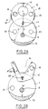
- a device according to the invention is shown in longitudinal section in FIG. 1 and in cross section in FIG. 2A.
- the device comprises a main part 1 in particular made of stainless metal, which is a cylinder of approximately 80 mm in length, the circular section of which has a diameter of 25 mm for example.
- This part 1 is held at a boss 2 on the wall of the fermenter tank by a cover 3 of which the part 1 is integral and which is screwed to the boss 2.
- On any diameter of the cross section of the main part - diameter defining the cutting plane of Figure 1- two holes of the same length 4 and 5 are drilled in the main part, on either side of the center of the diameter, at any distance.
- the holes in the same direction as the axis of the part 1, cross the main part over almost its entire length, the non-perforated part, opposite the end attached to the cover 3 being defined as the lower part of the part.
- a deep cut 6 along a plane perpendicular to the axis of the main part is made.
- This notch has for axis of symmetry an axis parallel to the diameter passing through the holes 4 and 5, and has a width between 5 and 15 mm. It constitutes the housing of the main room where the moving part will be housed.
- the notch is limited by two parallel flanks, the upper flank 7 and the lower flank 16.
- the notch separates the upper part of the main part, closest to the wall of the tank, from its lower part 26.
- the surfaces two two sides 7 and 16 are in principle equal, however the surface of the sidewall 16 may be reduced due to the elimination of the non-useful volume of the lower part 26, this in order to save material, as shown in FIGS. 1, 3A and 3B.
- the bottom of the notch is machined in an arc, the center of which is located on the lower end of the axis of rotation 29, at its attachment to the moving part, and whose radius is greater than that of the section. right of the main room.
- This radius is such that the thickness of the bottom 13 is such that this bottom offers sufficient resistance depending, among other things, on the force exerted on the lower part of the main part.
- the bottom 13 connecting the upper part of the main part to its lower part and whose bottom of the cut constitutes one face has a section in the shape of a crescent moon, as shown in FIGS. 2A and 2B.
- Each of the holes 4 and 5 opens onto the upper flank 7 of the notch.
- the fibers are grouped together glued and polished, their surface exactly coinciding with the side of the notch.
- half of the fibers are connected, through the cover 3, to a light source 9, the second half of the fibers being connected, through the cover 3, to a photometer 10, the fibers connected at the source or the analyzer being distributed randomly in the bundle 8.
- the bundle of simple fibers can be replaced by a bundle of bifurcated fibers having three branches connected at a coupling point.
- One is taken by the light flow back and forth and is located in the hole 5, the second connects the coupling point to the light source 9, the third connects the coupling point to the photometer 10.
- the coupling branches are made at level cover 3 or outside the boss. The source and photometer are outside the tank.
- the fibers can be made of quartz, resistant to temperatures of several hundred degrees.
- an axis of rotation 29 connected through the fixing cover 3 to a control motor 11 external to the tank, and at its other end to an off-center point of a cylindrical moving part 12, in particular in stainless metal, in abutment against the upper flank 7 of the notch.
- This moving part is a disc whose thickness is equal to the width of the notch 6.
- the diameter of the moving part is greater than the distance D which exists between the axis of rotation and the optical beam, and is less than the diameter of the main part.
- the distance d between the axis of rotation 29 and the point furthest from the disc 12 will be equal to or less than the radius of the circle along which the bottom of the notch is machined, so that the moving part can rotate 180 ° around the axis of rotation.
- the dimensions of the parts are calculated so that the lateral face of the moving part and the bottom of the notch are contiguous for a position of the disc, called “closed”, obtained after rotation of 180 ° relative to the position, called “open” shown in Figures 2A or 2B.
- the movable part is pierced over its entire thickness with a cylindrical hole 14 of diameter greater than that of the bundle of optical fibers, so as to define a cavity open on the outside of the movable part by two circular orifices 30 and 31 of the same surface, each located on one side of the disc and opposite.
- the fluid in which the lower part of the apparatus, including the moving part, soaks can circulate freely in the cavity, for certain positions of the disc, called open positions.
- the distance between the center of this cavity and the axis of rotation is equal to the distance D which exists between the axis of rotation and the bundle of optical fibers so that there is a particular position, during the rotation of the disc around the axis of rotation, called the closed position, for which the cylinder 14 is exactly in line with the bundle of optical fibers.
- a convex reflecting mirror with a flat external surface 15 is embedded in the lower flank of the notch, exactly in line with the fiber bundle 8.
- the reflector, the cylindrical cavity and its orifices and the end of the beam are aligned, and the light flux, brought by the fibers "go" of the beam 8, is reflected on this mirror 15 after passing through the cavity 14 formed in the moving part containing a sample of the medium to be studied, and is returned on the end of the beam to be taken back by the fibers "back” to the light analyzer 10, here a photometer.
- O-rings 17 placed around the axis of rotation 29 and of the bundle 8 near the upper flank 7 of the notch.
- D be the distance between the axis of rotation and the center of the hole containing the bundle of optical fibers.
- two cylindrical glass bars 18 and 19 of length equal to the thickness of the moving part, and of diameter substantially equal to the diameter of the bundle of optical fibers, are included in the part mobile, along axes perpendicular to the bases of the part.
- the bars and the end of the optical beam are located on the same circle of radius D and of center of the axis of rotation, so that during the rotation of the moving part around the axis of rotation, each of the bars is at one point in the extension of the optical fiber bundle, between the end of the bundle and the mirror 15.
- the bars are made of quartz, treated so that their transmission coefficients are different, to sweep a greater dynamic range than with a bar unique, without disassembly.
- the axis of rotation and of radius D are placed on each side of the notch of the main part two small bristle brushes 20 and 21, 32 and 33.
- the brushes are intended to clean the surfaces light bars during the rotation of the moving part.
- Small brushes 22, 23, 24, 25 intended for cleaning the surfaces of the bundle of optical fibers and surface of the mirror are fixed on the side wall of the moving part in pairs and back to back so that the bristles slightly protrude from the bases upper and lower of the moving part
- the brushes are placed on the periphery of the moving part so that they pass over the optical surfaces - end of the optical beam and surface of the reflector - during the rotation of the moving part.
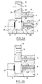
- FIGS. 2B, 3A and 3B show other possible embodiments of the moving part animated by a rotational movement, in particular different shapes which the cavity which will contain the liquid sample on which the measurement will be made can take. .
- the moving part has roughly the shape of a U with thick branches, the volume is opened onto the reaction medium by the upper and lower bases of the part and also by the side. Only one calibration bar is provided here.
- the device will advantageously be inclined or oriented so that these bubbles gather in a so-called upper angle of the sector, the density measurement being carried out at the lower part thereof.
- the volume 14 is a divergent cone with an axis of symmetry similarly direction as the axis of the main room.
- the volume has a T-shaped section.
- the convex mirror of FIG. 1 can advantageously be replaced by a plane mirror 27, and a collimating lens 28 resistant to high temperatures of the order of 750 ° F is inserted between the end of the fiber bundle.
Landscapes
- Chemical & Material Sciences (AREA)
- Health & Medical Sciences (AREA)
- Life Sciences & Earth Sciences (AREA)
- Zoology (AREA)
- Analytical Chemistry (AREA)
- Engineering & Computer Science (AREA)
- Bioinformatics & Cheminformatics (AREA)
- Organic Chemistry (AREA)
- General Health & Medical Sciences (AREA)
- Biochemistry (AREA)
- Wood Science & Technology (AREA)
- Biomedical Technology (AREA)
- Sustainable Development (AREA)
- General Engineering & Computer Science (AREA)
- Microbiology (AREA)
- Genetics & Genomics (AREA)
- Biotechnology (AREA)
- Physics & Mathematics (AREA)
- General Physics & Mathematics (AREA)
- Immunology (AREA)
- Pathology (AREA)
- Investigating Or Analysing Materials By Optical Means (AREA)
- Apparatus Associated With Microorganisms And Enzymes (AREA)
- Optical Measuring Cells (AREA)
Claims (12)
- Vorrichtung zur In-Situ-Messung der optischen Dichte eines Mediums, gekennzeichnet durch- ein den Körper der Vorrichtung bildendes Hauptglied (1), in dem eine Aufnahme (6) ausgespart ist,- einem beweglichen Glied (12), das in der Aufnahme aufgenommen werden kann und in dem ein Hohlraum (14) ausgespart ist, der zur Außenseite des beweglichen Gliedes über wenigstens zwei gegenüberliegende Öffnungen (30, 31) offen ist, die aneinanderstoßen können,- optischen Einrichtungen (8, 15), (8, 28, 27), die in dem Hauptglied auf beiden Seiten der Aufnahme enthalten sind, um einen Lichtstrom von einer Quelle zu einem Lichtanalysator zu leiten, und- Einrichtungen zur Verschiebung des beweglichen Gliedes aus einer offenen Stellung, in der das zu untersuchende Medium frei in dem Hohlraum des beweglichen Gliedes zirkuliert, in eine geschlossene Stellung, in der das bewegliche Glied in der Aufnahme des Hauptgliedes so eingeschlossen ist, daß der Hohlraum und sein Inhalt, der aus der Probe des zu analysierenden Mediums besteht, mit dem die Messung durchgefährt wird, von dem zu untersuchenden Medium isoliert sind, wobei die optischen Einrichtungen entsprechend der Lage der Öffnungen des beweglichen Gliedes angepaßt sind, damit der Lichtstrom den Inhalt des Hohlraums durchquert, wenn das bewegliche Teil sich in der geschlossenen Stellung befindet.
- Vorrichtung nach Anspruch 1, dadurch gekennzeichnet, daß sie Einrichtungen (18, 19) zur Eichung der Intensität des Lichtstroms und Einrichtungen (20, 21, 22, 23, 24, 25, 32, 33) zur Reinigung der optischen Flächen aufweist.
- Vorrichtung nach Anspruch 2, dadurch gekennzeichnet, daß die Einrichtungen zur Eichung von wenigstens einem optischen Gitter mit bekannten Eigenschaften gebildet werden, das vorübergehend wenigstens auf dem optischen Weg des Lichtstroms angeordnet ist.
- Vorrichtung nach Anspruch 3, dadurch gekennzeichnet, daß die Einrichtungen zur Eichung von mehreren Eichgittern gebildet werden, die unterschiedliche Durchlässigkeitsfaktoren aufweisen.
- Vorrichtung nach Anspruch 3 oder 4, dadurch gekennzeichnet, daß die Eichgitter in der Dicke des beweglichen Gliedes angeordnet sind.
- Vorrichtung nach Anspruch 2, dadurch gekennzeichnet, daß die Reinigungseinrichtungen von Abstreifern oder Bürsten, die auf dem beweglichen Glied zur Reinigung der optischen Flächen des Hauptgliedes angeordnet sind, und von Abstreifern oder Bürsten gebildet werden, die auf dem Hauptglied zur Reinigung der optischen Flächen des beweglichen Gliedes angeordnet sind.
- Vorrichtung nach Anspruch 1 oder 2, dadurch gekennzeichnet, daß sie von Elementen gebildet wird, die gegen die Sterilisationstemperatur beständig sind.
- Vorrichtung nach Anspruch 1 oder 2, dadurch gekennzeichnet, daß die Einrichtungen zur Verschiebung des beweglichen Gliedes eine mit dem beweglichen Glied verbundene Drehachse (29) und einen Motor (11) umfassen, der die Drehung der Achse sicherstellt.
- Vorrichtung nach Anspruch 1 oder 2, dadurch gekennzeichnet, daß die optischen Einrichtungen von einem sich gabelnden Faserbündel (8), das die Aufnahme (6) einerseits mit der Quelle (9) und andererseits mit dem Lichtanalysator (10) verbindet, und von einem Reflektor (15, 27) gebildet werden, der an der Flache der Aufnahme angeordnet ist, die dem Ende des Faserbändels gegenüberliegt.
- Vorrichtung nach Anspruch 1, dadurch gekennzeichnet, daß das bewegliche Glied eine Scheibe ist, deren Grundflächen in einen Kreis eingeschrieben sind, und deren Dicke gleich der Breite eines Schlitzes ist, der in der Nähe eines Endes des Hauptgliedes senkrecht zur Längsachse des Hauptgliedes vorgesehen ist und die Aufnahme bildet.
- Vorrichtung nach Anspruch 10, dadurch gekennzeichnet, daß der Hohlraum des beweglichen Gliedes eine Symmetrieachse hat, die zu den Grundflächen der Scheibe senkrecht ist, wobei der Hohlraum zur Außenseite über zwei Öffnungen offen ist, die einen kreisförmigen Querschnitt haben.
- Vorrichtung nach Anspruch 10, dadurch gekennzeichnet, daß der in dem beweglichen Glied ausgesparte Hohlraum ein Sektor des Gliedes ist.
Applications Claiming Priority (2)
| Application Number | Priority Date | Filing Date | Title |
|---|---|---|---|
| FR8901165A FR2642522B1 (fr) | 1989-01-31 | 1989-01-31 | Appareil de mesure de densite optique in situ pour fermenteur |
| FR8901165 | 1989-01-31 |
Publications (2)
| Publication Number | Publication Date |
|---|---|
| EP0456708A1 EP0456708A1 (de) | 1991-11-21 |
| EP0456708B1 true EP0456708B1 (de) | 1993-04-21 |
Family
ID=9378284
Family Applications (1)
| Application Number | Title | Priority Date | Filing Date |
|---|---|---|---|
| EP90902793A Expired - Lifetime EP0456708B1 (de) | 1989-01-31 | 1990-01-30 | Vorrichtung, um die optische dichte in situ zu messen |
Country Status (6)
| Country | Link |
|---|---|
| US (1) | US5243409A (de) |
| EP (1) | EP0456708B1 (de) |
| JP (1) | JPH04503005A (de) |
| DE (1) | DE69001431T2 (de) |
| FR (1) | FR2642522B1 (de) |
| WO (1) | WO1990008818A1 (de) |
Families Citing this family (19)
| Publication number | Priority date | Publication date | Assignee | Title |
|---|---|---|---|---|
| US5278412A (en) * | 1992-08-18 | 1994-01-11 | Nirsystems Incorporated | System for measuring the moisture content of powder and fiber optic probe therefor |
| US5587788A (en) * | 1993-07-28 | 1996-12-24 | Texas Instruments Incorporated | Sampling apparatus for inline spectrographic analysis of viscous materials |
| JPH07103897A (ja) * | 1993-09-30 | 1995-04-21 | Shimadzu Corp | 発光分光分析装置 |
| US5601997A (en) | 1995-02-03 | 1997-02-11 | Tchao; Ruy | Chemotaxis assay procedure |
| US6040904A (en) * | 1998-12-23 | 2000-03-21 | Eastman Kodak Company | Diffuse optical transmission density measurement system |
| DE10016838B4 (de) * | 2000-04-05 | 2006-10-19 | Jan-Gerd Dipl.-Ing. Frerichs | In-situ Mikroskopvorrichtung für Reaktoren |
| ES2185496B1 (es) * | 2001-07-17 | 2005-06-01 | Universidad Politecnica De Valencia | Equipo y metodo en linea para la deteccion, determinacion de la evolucion y cuantificacion de biomasa microbiana y otras sustancias que absorben a lo largo del espectro de luz durante el desarrollo de procesos biotecnologicos. |
| US7061616B2 (en) * | 2002-03-28 | 2006-06-13 | Samsung Electronics Co., Ltd. | Optical transceiver and method for image density measurement |
| FR2867279B1 (fr) * | 2004-03-05 | 2006-05-19 | Nanotec Solution | Procede et dispositif pour mesurer et caracteriser une biomasse, application a une mesure en ligne de donnees de biomasse dans un processus de fermentation, et procede de pilotage associe |
| FR2867278B1 (fr) * | 2004-03-05 | 2006-05-19 | Univ Montpellier Ii | Procede et dispositif pour mesurer et caracteriser en ligne une biomasse dans un processus de fermentation de bacteries lactiques, et procede de pilotage associe |
| EP2023123B1 (de) * | 2007-07-26 | 2017-06-21 | Shimadzu Corporation | Optisches Messgerät |
| EP2594334A1 (de) | 2011-11-21 | 2013-05-22 | Drive O2 | Probenfläschchen zur digitalen holographischen Analyse einer flüssigen Zellprobe |
| CA2842377C (en) | 2011-07-19 | 2019-08-27 | Ovizio Imaging Systems N.V. | A method and system for detecting and/or classifying cancerous cells in a cell sample |
| EP2626686A1 (de) | 2012-02-13 | 2013-08-14 | Ovizio Imaging Systems NV/SA | Durchflusszytometer mit digitalem holografischen Mikroskop |
| EP2898310B1 (de) | 2012-09-20 | 2019-05-01 | Ovizio Imaging Systems NV/SA | Digitales holografisches mikroskop mit fluidsysteme |
| US9675974B2 (en) * | 2013-07-31 | 2017-06-13 | Ovizio Imaging Systems NV/SA | Cap for monitoring objects in suspension |
| CN105593665A (zh) * | 2013-10-04 | 2016-05-18 | 梅西大学 | 原位光密度传感器 |
| JP2017032413A (ja) * | 2015-07-31 | 2017-02-09 | ソニー株式会社 | 検出用デバイス、光学的検出用装置及び光学的検出方法 |
| EP3196631A1 (de) | 2016-01-19 | 2017-07-26 | Ovizio Imaging Systems NV/SA | Digitales holografisches mikroskop mit elektrofluidischem system, besagtes elektrofluidisches system und verfahren zur verwendung |
Family Cites Families (19)
| Publication number | Priority date | Publication date | Assignee | Title |
|---|---|---|---|---|
| US2866379A (en) * | 1957-02-18 | 1958-12-30 | Askania Werke Ag | Turbidimeter |
| US3164663A (en) * | 1960-10-27 | 1965-01-05 | Beckman Instruments Inc | Probe for colorimetric measurement |
| US3876307A (en) * | 1969-08-05 | 1975-04-08 | Environmental Technology | Optical fluid contamination and change monitor |
| DE1959612A1 (de) * | 1969-11-27 | 1971-06-03 | Eppendorf Geraetebau Netheler | Vorrichtung zur fotometrischen Messung |
| US3814930A (en) * | 1970-11-05 | 1974-06-04 | A Lindberg | Determining and following a sedimentation level by optical measurement |
| GB1409196A (en) * | 1973-04-06 | 1975-10-08 | Shandon Southern Instr Ltd | Colourimeters and colourimetric analysis |
| CH584290A5 (de) * | 1974-03-18 | 1977-01-31 | Mueller Hans Maennedorf | |
| SE7410610L (sv) * | 1974-08-21 | 1976-02-23 | Lkb Produkter Ab | Optiskt system i en odlingstank. |
| JPS602614B2 (ja) * | 1976-08-06 | 1985-01-23 | コニカ株式会社 | 液体濃度検出装置 |
| JPS5338388A (en) * | 1976-09-20 | 1978-04-08 | Sanyo Electric Co Ltd | Gas concentration analyzer |
| US4085618A (en) * | 1976-10-27 | 1978-04-25 | Collins Products Company | Composite sampling system and rotatable sampling valve therefor |
| FR2390725A1 (fr) * | 1977-05-13 | 1978-12-08 | Commissariat Energie Atomique | Dispositif de photometrie a miroirs concaves et a optique de champ |
| US4451152A (en) * | 1981-04-16 | 1984-05-29 | Monitek, Inc. | Method for measuring the radiation transmitting properties of a fluid |
| JPS6044851A (ja) * | 1983-08-22 | 1985-03-11 | Shimadzu Corp | 分光光度計 |
| JPS60259935A (ja) * | 1984-06-07 | 1985-12-23 | Komatsugawa Kakoki Kk | 濁度計 |
| JPS6165123A (ja) * | 1984-09-06 | 1986-04-03 | Kansai Panpu Kagaku Bosui Kk | 光フアイバ−による着色溶液の連続測色方法 |
| JPH0711485B2 (ja) * | 1985-02-18 | 1995-02-08 | オリンパス光学工業株式会社 | 液体濃度測定装置 |
| JPH0718802B2 (ja) * | 1986-09-05 | 1995-03-06 | 花王株式会社 | 分相滴定用終点検出装置 |
| US5046854A (en) * | 1990-02-01 | 1991-09-10 | The Dow Chemical Company | Photometric cell and probe having windows fusion sealed to a metallic body |
-
1989
- 1989-01-31 FR FR8901165A patent/FR2642522B1/fr not_active Expired - Fee Related
-
1990
- 1990-01-30 JP JP2502979A patent/JPH04503005A/ja active Pending
- 1990-01-30 US US07/730,944 patent/US5243409A/en not_active Expired - Fee Related
- 1990-01-30 EP EP90902793A patent/EP0456708B1/de not_active Expired - Lifetime
- 1990-01-30 WO PCT/FR1990/000072 patent/WO1990008818A1/fr not_active Ceased
- 1990-01-30 DE DE90902793T patent/DE69001431T2/de not_active Expired - Fee Related
Non-Patent Citations (1)
| Title |
|---|
| Patent Abstracts of Japan volume 9, no. 167 (P-372 (1980), 12 juillet 1985 * |
Also Published As
| Publication number | Publication date |
|---|---|
| WO1990008818A1 (fr) | 1990-08-09 |
| JPH04503005A (ja) | 1992-06-04 |
| FR2642522B1 (fr) | 1991-05-10 |
| EP0456708A1 (de) | 1991-11-21 |
| FR2642522A1 (fr) | 1990-08-03 |
| DE69001431T2 (de) | 1993-10-07 |
| DE69001431D1 (de) | 1993-05-27 |
| US5243409A (en) | 1993-09-07 |
Similar Documents
| Publication | Publication Date | Title |
|---|---|---|
| EP0456708B1 (de) | Vorrichtung, um die optische dichte in situ zu messen | |
| FR2549224A1 (fr) | Mesure par des moyens optiques de parametres d'un fluide | |
| EP0015170B1 (de) | Spektrofotometrische Vorrichtung mit Fernmessung | |
| EP0025586A1 (de) | Vorrichtung für optische Kupplung | |
| FR2587119A1 (fr) | Appareil optique servant a effectuer des analyses | |
| EP2364438A1 (de) | Verfahren und system zur analyse von feststoffteilchen in einem medium | |
| EP0033253A2 (de) | Photometrische Messeinrichtung für komplexe Lösungen mit verändertem Hintergrundgeräusch | |
| EP3210938B1 (de) | Vorrichtung zur charakterisierug von in einem flüssigen medium dispergierten teilchen | |
| EP0654661B1 (de) | Streulichtintensitätsdetektor für von Filmen in kolloidalen Medien gestreutes Licht | |
| EP1410000B1 (de) | Einrichtung zur laserinduzierten fluoreszenzanalyse und trennvorrichtung damit | |
| FR2693796A1 (fr) | Réfractomètre. | |
| EP2649431B1 (de) | System und verfahren für multitechnische bildgebung zur chemischen, biologischen oder biochemischen analyse einer probe | |
| Song et al. | Application of liquid waveguide to Raman spectroscopy in aqueous solution | |
| EP1563293B1 (de) | Verfahren zur bestimmung der verflüchtigungstemperatur von erdölproduktkristallen und einrichtung dafür | |
| EP0237415A1 (de) | Vorrichtung zur spektralphotometrischen Ellipsometrie mit Verwendung optischer Fasern | |
| EP3452807B1 (de) | Analysesystem umfassend eine begrenzungsvorrichtung mit einer teilweise durch eine flexible membran begrenzten messkammer variabler grösse | |
| WO1986007454A1 (fr) | Procede et dispositif pour determiner la couleur et le degre de turbidite d'un fluide | |
| FR2766922A1 (fr) | Instrument de mesure de l'indice de refraction d'un fluide | |
| FR3036801B1 (fr) | Sonde immergeable a site de mesure de taille variable | |
| EP0263743B1 (de) | Verfahren und Vorrichtung zur Messung nichtlinearer optischer Eigenschaften dritter Ordnung in einer isotropen Phase | |
| EP0064110B1 (de) | Streuungsphotometer | |
| FR2831182A1 (fr) | Bio-reacteur pour le controle et/ou la culture en milieu liquide d'organismes vivants | |
| EP2446245B1 (de) | Verbesserter partikelgrössenanalysator | |
| FR2774887A1 (fr) | Capteur optique sur substrat de silicium et application a la mesure in situ d'un marqueur fluorescent dans les petites bronches | |
| FR2915827A1 (fr) | Procede et systeme de lecture d'informations optiques a haute densite. |
Legal Events
| Date | Code | Title | Description |
|---|---|---|---|
| PUAI | Public reference made under article 153(3) epc to a published international application that has entered the european phase |
Free format text: ORIGINAL CODE: 0009012 |
|
| 17P | Request for examination filed |
Effective date: 19910724 |
|
| AK | Designated contracting states |
Kind code of ref document: A1 Designated state(s): CH DE FR GB LI |
|
| 17Q | First examination report despatched |
Effective date: 19920630 |
|
| GRAA | (expected) grant |
Free format text: ORIGINAL CODE: 0009210 |
|
| AK | Designated contracting states |
Kind code of ref document: B1 Designated state(s): CH DE FR GB LI |
|
| REF | Corresponds to: |
Ref document number: 69001431 Country of ref document: DE Date of ref document: 19930527 |
|
| RAP2 | Party data changed (patent owner data changed or rights of a patent transferred) |
Owner name: SOCIETE NATIONALE ELF AQUITAINE |
|
| GBT | Gb: translation of ep patent filed (gb section 77(6)(a)/1977) |
Effective date: 19930527 |
|
| PLBE | No opposition filed within time limit |
Free format text: ORIGINAL CODE: 0009261 |
|
| STAA | Information on the status of an ep patent application or granted ep patent |
Free format text: STATUS: NO OPPOSITION FILED WITHIN TIME LIMIT |
|
| 26N | No opposition filed | ||
| PGFP | Annual fee paid to national office [announced via postgrant information from national office to epo] |
Ref country code: CH Payment date: 19951221 Year of fee payment: 7 |
|
| PGFP | Annual fee paid to national office [announced via postgrant information from national office to epo] |
Ref country code: FR Payment date: 19960131 Year of fee payment: 7 |
|
| PGFP | Annual fee paid to national office [announced via postgrant information from national office to epo] |
Ref country code: GB Payment date: 19961219 Year of fee payment: 8 |
|
| PGFP | Annual fee paid to national office [announced via postgrant information from national office to epo] |
Ref country code: DE Payment date: 19961228 Year of fee payment: 8 |
|
| PG25 | Lapsed in a contracting state [announced via postgrant information from national office to epo] |
Ref country code: LI Effective date: 19970131 Ref country code: CH Effective date: 19970131 |
|
| REG | Reference to a national code |
Ref country code: CH Ref legal event code: PL |
|
| PG25 | Lapsed in a contracting state [announced via postgrant information from national office to epo] |
Ref country code: FR Effective date: 19970930 |
|
| REG | Reference to a national code |
Ref country code: FR Ref legal event code: ST |
|
| PG25 | Lapsed in a contracting state [announced via postgrant information from national office to epo] |
Ref country code: GB Free format text: LAPSE BECAUSE OF NON-PAYMENT OF DUE FEES Effective date: 19980130 |
|
| GBPC | Gb: european patent ceased through non-payment of renewal fee |
Effective date: 19980130 |
|
| PG25 | Lapsed in a contracting state [announced via postgrant information from national office to epo] |
Ref country code: DE Free format text: LAPSE BECAUSE OF NON-PAYMENT OF DUE FEES Effective date: 19981001 |