EP0456728B1 - Systeme d'alimentation electrique - Google Patents
Systeme d'alimentation electrique Download PDFInfo
- Publication number
- EP0456728B1 EP0456728B1 EP90902981A EP90902981A EP0456728B1 EP 0456728 B1 EP0456728 B1 EP 0456728B1 EP 90902981 A EP90902981 A EP 90902981A EP 90902981 A EP90902981 A EP 90902981A EP 0456728 B1 EP0456728 B1 EP 0456728B1
- Authority
- EP
- European Patent Office
- Prior art keywords
- load
- power
- request
- bus
- supply
- Prior art date
- Legal status (The legal status is an assumption and is not a legal conclusion. Google has not performed a legal analysis and makes no representation as to the accuracy of the status listed.)
- Expired - Lifetime
Links
Images

Classifications
-
- H—ELECTRICITY
- H02—GENERATION; CONVERSION OR DISTRIBUTION OF ELECTRIC POWER
- H02J—ELECTRIC POWER NETWORKS; CIRCUIT ARRANGEMENTS OR SYSTEMS FOR SUPPLYING OR DISTRIBUTING ELECTRIC POWER; SYSTEMS FOR STORING ELECTRIC ENERGY
- H02J1/00—Circuit arrangements for DC mains or DC distribution networks
- H02J1/08—Three-wire DC power distribution systems; Systems having more than three wires
-
- H—ELECTRICITY
- H02—GENERATION; CONVERSION OR DISTRIBUTION OF ELECTRIC POWER
- H02J—ELECTRIC POWER NETWORKS; CIRCUIT ARRANGEMENTS OR SYSTEMS FOR SUPPLYING OR DISTRIBUTING ELECTRIC POWER; SYSTEMS FOR STORING ELECTRIC ENERGY
- H02J1/00—Circuit arrangements for DC mains or DC distribution networks
- H02J1/14—Balancing load and power generation in DC networks
-
- H—ELECTRICITY
- H02—GENERATION; CONVERSION OR DISTRIBUTION OF ELECTRIC POWER
- H02J—ELECTRIC POWER NETWORKS; CIRCUIT ARRANGEMENTS OR SYSTEMS FOR SUPPLYING OR DISTRIBUTING ELECTRIC POWER; SYSTEMS FOR STORING ELECTRIC ENERGY
- H02J3/00—Circuit arrangements for AC mains or AC distribution networks
- H02J3/12—Arrangements for adjusting voltage in AC networks by changing a characteristic of the network load
- H02J3/14—Arrangements for adjusting voltage in AC networks by changing a characteristic of the network load by switching loads on to, or off from, the networks, e.g. progressively balanced loading
-
- H—ELECTRICITY
- H03—ELECTRONIC CIRCUITRY
- H03K—PULSE TECHNIQUE
- H03K17/00—Electronic switching or gating, i.e. not by contact-making and –breaking
- H03K17/08—Modifications for protecting switching circuit against overcurrent or overvoltage
- H03K17/081—Modifications for protecting switching circuit against overcurrent or overvoltage without feedback from the output circuit to the control circuit
- H03K17/0814—Modifications for protecting switching circuit against overcurrent or overvoltage without feedback from the output circuit to the control circuit by measures taken in the output circuit
- H03K17/08146—Modifications for protecting switching circuit against overcurrent or overvoltage without feedback from the output circuit to the control circuit by measures taken in the output circuit in bipolar transistor switches
-
- H—ELECTRICITY
- H02—GENERATION; CONVERSION OR DISTRIBUTION OF ELECTRIC POWER
- H02J—ELECTRIC POWER NETWORKS; CIRCUIT ARRANGEMENTS OR SYSTEMS FOR SUPPLYING OR DISTRIBUTING ELECTRIC POWER; SYSTEMS FOR STORING ELECTRIC ENERGY
- H02J13/00—Circuit arrangements for providing remote monitoring or remote control of equipment in a power distribution network
- H02J13/13—Circuit arrangements for providing remote monitoring or remote control of equipment in a power distribution network characterised by the transmission of data to equipment in the power network
- H02J13/1321—Circuit arrangements for providing remote monitoring or remote control of equipment in a power distribution network characterised by the transmission of data to equipment in the power network using a wired telecommunication network or a data transmission bus
-
- H—ELECTRICITY
- H02—GENERATION; CONVERSION OR DISTRIBUTION OF ELECTRIC POWER
- H02J—ELECTRIC POWER NETWORKS; CIRCUIT ARRANGEMENTS OR SYSTEMS FOR SUPPLYING OR DISTRIBUTING ELECTRIC POWER; SYSTEMS FOR STORING ELECTRIC ENERGY
- H02J2105/00—Networks for supplying or distributing electric power characterised by their spatial reach or by the load
- H02J2105/10—Local stationary networks having a local or delimited stationary reach
- H02J2105/12—Local stationary networks having a local or delimited stationary reach supplying households or buildings
-
- H—ELECTRICITY
- H02—GENERATION; CONVERSION OR DISTRIBUTION OF ELECTRIC POWER
- H02J—ELECTRIC POWER NETWORKS; CIRCUIT ARRANGEMENTS OR SYSTEMS FOR SUPPLYING OR DISTRIBUTING ELECTRIC POWER; SYSTEMS FOR STORING ELECTRIC ENERGY
- H02J2105/00—Networks for supplying or distributing electric power characterised by their spatial reach or by the load
- H02J2105/50—Networks for supplying or distributing electric power characterised by their spatial reach or by the load for selectively controlling the operation of the loads
- H02J2105/59—Networks for supplying or distributing electric power characterised by their spatial reach or by the load for selectively controlling the operation of the loads one of the loads acting as leader and the other or others acting as followers
-
- H—ELECTRICITY
- H02—GENERATION; CONVERSION OR DISTRIBUTION OF ELECTRIC POWER
- H02J—ELECTRIC POWER NETWORKS; CIRCUIT ARRANGEMENTS OR SYSTEMS FOR SUPPLYING OR DISTRIBUTING ELECTRIC POWER; SYSTEMS FOR STORING ELECTRIC ENERGY
- H02J4/00—Circuit arrangements for mains or distribution networks not specified as AC or DC; Circuit arrangements for mains or distribution networks combining AC and DC sections or sub-networks
- H02J4/20—Networks integrating separated AC and DC power sections
- H02J4/25—Networks integrating separated AC and DC power sections for transfer of electric power between AC and DC networks, e.g. for supplying the DC section within a load from an AC mains system
Definitions
- This invention relates to a power supply system for use in conjunction with a plurality of electrical loads, and has particular but not exclusive application in the control of lift machines.
- DC machines In modern lift installations, it is common to use DC machines as the prime-mover for lift cars and their associated counterweights; these machines being connected to the ropes suspending the lift cars and counterweights via a gearbox, or alternatively through direct connection to the sheave wheel. Since lift cars must travel in both the upward and downward directions, DC machines are required to be controllable direction-wise and have precise speed control.
- Pulse width modulated (PWM) convertors are often used in conjunction with DC machines to provide either two or four quadrant control over the machine.
- a four quadrant control allows for the regeneration of power into the supply network during deceleration of the lift car.
- PWM convertors usually operate from a multi-phase AC supply, which supply is then rectified and controlled to give the appropriate output voltage and polarity to achieve the desired speed and direction of rotation of the DC machine.
- AC-AC convertors are most often used whereby the multi-phase supply is rectified to a DC bus, then inverted to provide the required output frequency in voltage, in turn to cause the AC machine to operate the desired speed with the requisite torque.
- cycloconvertors can provide direct frequency conversion synthesizing lower frequency outputs from the mains supply.
- lift drives be of low cost, have low radiated acoustic noise and radio frequency interference, and can provide at least partial service under all supply conditions.
- the discussed known systems have the drawback of being particularly costly and complex.
- Circuit breakers are not cost effective in protecting DC drives from localised faults such as output short circuits, and can often cause significant damage to both the motor and the convertor.
- constant field (synchronous) machines offer advantages over the cheaper induction (non-synchronous) motors. They can provide inherent braking capability on power loss where a stator load is provided and especially if permanent magnetic fields are used, the air gap is large enough to allow reasonably lightweight design providing for deflection as a result of lateral rotor loads, and afford greater efficiency at low speed or stall conditions.
- GB-A-2071438 One prior system is known in GB-A-2071438.
- the specification of this patent application discloses a power supply system which limits the power drawn from an output supply to no greater than a pre-determined maximum.
- the system comprises a power supply which is adapted to generate output supply. It also discloses a plurality of loads which can each make a demand for power from the power supply. It also discloses a plurality of load controllers each interposed between the output supply and the load and are controllable to connect or disconnect the load to or from the output supply.
- a supply controller is provided which can communicate with the load controllers and receives requests for power from each load controller which indicate the demand of power by the respective loads.
- the supply controller does not authorise a request for the power demand of a particular load if it would result in the total demand for power from all loads being greater than the power that is available from the power supply. Such disclosure does not determine if the request for power from a particular load is greater than a predetermined limit for that load and in that event not authorising the request or disconnecting the load.
- the present invention as defined in independent claims 1 and 2 includes the feature of determining if a request by a load for power is greater than a predetermined limit for that load and in that event it does not authorise that request.
- This offers many advantages in particular examples of the present invention because if the individual load is requesting power greater than a predetermined limit, it is assumed that there is a fault on that load. Thus, by not authorising the request it will provide them to extinguish any arc which may be occurring. Thus, the system permits better control in such situations.
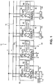
- Figure 1 shows a multi-load system 10 as could be implemented in a building having a number of lifts forming electrical loads. Some of the lifts may be installed in the one motor room whilst others may be located in a separate motor room at another level in the building.
- the capability of a distributed lifting system having a single point of supply and control is a particular advantage of the embodiment.
- the three phase AC supply 12 providing power to the whole of the system 10 is shown input to the AC-DC convertor 14.
- the convertor 14 rectifies the mains supply 12 to provide a DC voltage, which forms the driving point for DC bus 16, comprising positive and negative rails as shown.
- the convertor 14 is responsible for the generation of all power for loads attached to the system 10.
- the DC output from the convertor 14 is shown at terminals 18 and 20, including the relative polarity. Terminals 18 and 20 are then connected to the DC bus 16 through the controlling switchgear of master controller 22.
- This switch gear comprises a control contactor 24 in each of the power lines together with fuse elements 26 and current sensing devices 28. Both the contactors 24 and current sensing devices 28 are under the control of master control processor 30.
- the master control processor 30 also provides and receives data signals to and from the data bus 32 via line 34, as well as sending or receiving data signals from the convertor 14 along line 36.
- the system 10 further comprises two loads 38 and 40, which are lift drives, together with a secondary supply bus 42 and accompanying data link 44 which are reticulated to other locations within the building.
- the secondary supply bus 42 is suitable for connection to a number of other loads in a remote location or locations within the building.
- the secondary supply bus 42 is connected to the DC bus 16 by a similar controller as that for the convertor 14, designated as slave controller 46.
- slave controller 46 the connection to data link 44 is via the slave controller 46, in turn being connected to data bus 32 by line 45.
- the system 10 shows two loads 38 and 40, each drawing power from DC bus 16 to which they are connected via respective slave controllers 46.
- slave control processors 48 are uniquely identified, since they serve a slightly different function to master control processor 30.
- Load 38 communicates data with slave control processor 48 on line 50, the processor 48 in turn communicating data with data bus 32 on line 52.
- the same situation occurs for load 40 with respective lines 54 and 56.
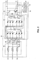
- FIG 2 shows the AC-DC convertor 14 of Figure 1 in more detail. Items common with Figure 1 are shown like-numbered.
- the three phase AC supply 12 is supplied from a phase splitting transformer (not shown) and is then rectified by the convertor 14 to produce the DC supply for DC bus 16. Connection to the DC bus 16 is via terminals 18 and 20.
- the supply 12 is firstly provided to an input filter section 58 which comprises inductance, resistance and capacitance elements, including the resistance and inductance of the AC supply 12 itself. Once the AC supply 12 has been filtered, it is then provided to rectifier section 60.
- the rectifier section 60 comprises dual six-pulse rectifiers. The dual system allows the rectifier section 60 to continue to function on a reduced power basis as a six-pulse system on failure of either bridge.
- each half bridge forms one rail of the DC output.
- the output of each half bridge is smoothed by mutually coupled inductors 62.
- a protection section 64 is also providing for protection of the DC output.
- Figure 2 also shows the master control processor 30 together with its interconnection to convertor 14 through line 36, and to data bus 32 through line 34.
- the master control processor 30 receives signals from current sensing devices in the protection section 64, and also from input current and voltage sensing section 66. All these signals are utilised in the control and protection logic appropriate for the convertor 14 as well as the overall system 10.
- FIG. 3 there is shown an example of a load within the system 10, which could be either load 38 or load 40.
- load 38 which comprises an AC motor 68, an accompanying brake mechanism 70, field controller 71, and drive invertor 72.
- Slave control processor 46 is shown interposed between the DC bus 16 and the drive invertor 72.
- the contactors 24, fuse elements 26 and current sensing devices 28 are shown within the slave controller 46 in accordance with the example of Figure 1.
- the drive invertor 72 comprises a six pulse bipolar junction transistor (BJT) bridge, which is under control of the digital signal processing (DSP) control element 74.
- the DSP control element 74 provides the necessary drive signals to the bases of the BJT's 76, and to the output contactors 78.
- the DSP control element 74 is under instruction from the slave control processor 48 via line 50, the slave control processor 48 in turn being under control of the master control processor 30 via the data bus 32 and line 52.
- the slave control processor 48 monitors the condition of the motor 68, the brake 70, the field controller 71, the drive invertor 72, and provides controlling instructions to the DSP control element 74 in order to operate the lift which has the motor 68 as the prime mover of the attached lift car and counterweight.
- each slave control processor 48 In normal operation, each slave control processor 48 must continuously request authorisation from the master control processor 40 for any demanded power. This request must be granted before allowing the DSP control element 74 to effect the demand of the motor. A power demand will usually be in respect of current.
- the interaction between the master control processor 30 and slave control processors 48 can best be described as a request and grant procedure.
- a special function provided is the detection of faults on any load connected to the DC bus 16. Any potential fault is signalled to the master control processor 30 by way of a usual power demand request. If the power demand request is for an amount of power greater than a predetermined value, the master control processor 30 assumes there is a fault then signals the load to disconnect from the DC bus 16 by operation of contactor 24 in the slave controller 46, or to load shed in an orderly manner, else to continue with normal operation depending on the type of fault experienced. A further action could be to require the DC bus 16 to power down through operation of contactors 24 in the master controller 22. There may also be the possibility of regeneration into the three phase AC supply 12.
- the DC bus 16 is compulsorily powered down as rapidly as possible by means of the contactors 24 in the master controller 22.
- the DC bus 16 may then be powered up after a deionisation period adequate to extinguish arcs in relays or fuses within any slave controller.
- the master control processor 30 will not authorise the particular slave control processor 48 to draw that demanded current, rather, the load must wait until the convertor 14 can provide the power at some later time. The result is that a lift car may be caused to pause at a floor until a demand request can be granted.
Landscapes
- Engineering & Computer Science (AREA)
- Power Engineering (AREA)
- Inverter Devices (AREA)
- Catching Or Destruction (AREA)
- Vehicle Body Suspensions (AREA)
- Input Circuits Of Receivers And Coupling Of Receivers And Audio Equipment (AREA)
- Supply And Distribution Of Alternating Current (AREA)
- Control Of Electrical Variables (AREA)
- Control Of Multiple Motors (AREA)
- Direct Current Feeding And Distribution (AREA)
Claims (3)
- Procédé de commande d'un système d'alimentation électrique (10) comprenant un convertisseur de courant alternatif en courant continu (14) connecté à une source d'alimentation d'entrée (12) et fournissant une alimentation de sortie (16), une pluralité de charges consommatrices (38, 40, 42) connectées à l'alimentation de sortie (16) par des unités de commande de charge respectives (46), et une unité de commande d'alimentation (22) en communication avec les unités de commande de charge (46) pour commander la dite alimentation de sortie (16), le procédé comprenant la détermination, par l'unité de commande d'alimentation (22), de ce qu'une demande présentée par une unité de commande de charge pour fournir une puissance à sa charge respective a pour effet que la demande totale de puissance de toutes les charges (38, 40, 42) dépasse une valeur maximale et, dans ce cas, la non acceptation de cette demande et la déconnexion de cette charge,
caractérisé par :(a) la détermination, par l'unité de commande d'alimentation (22), de ce qu'une demande présentée par une unité de commande de charge (46) pour la fourniture de puissance à sa charge respective (38, 40, 42) par la dite alimentation (16) est plus grande qu'une limite prédéterminée pour cette charge (38, 40, 42) et, dans ce cas, la non acceptation de cette demande et la déconnexion de cette charge ;(b) mais, dans le cas contraire, l'acceptation de la demande. - Système d'alimentation (10) comprenant un convertisseur de courant alternatif en courant continu (14) pour connexion à une source d'alimentation d'entrée (12) et pouvant fournir une alimentation de sortie (16), une pluralité de charges consommatrices (38, 40, 42) connectées à la dite alimentation de sortie (16) par des unités de commande de charge respectives (46), et une unité de commande d'alimentation (22) en communication avec les unités de commande de charge (46) pour commander la dite alimentation de sortie (16), la dite unité de commande d'alimentation (22) étant agencée de manière à répondre à une demande,présentée par une charge respective (38, 40, 42) pour une fourniture de puissance par la dite alimentation (16), afin de déterminer si la demande totale de puissance de toutes les charges (38, 40, 42) dépasse une valeur maximale et, dans ce cas, ne pas accepter la demande et déconnecter la charge,
caractérisé en ce que :l'unité de commande d'alimentation (22) est agencée pour répondre à une demande présentée par une charge respective (38, 40, 42) pour la fourniture de puissance par la dite alimentation (16), de manière à déterminer si la demande est plus grande qu'une limite prédéterminée pour cette charge (38, 40, 42) et, dans ce cas, ne pas accepter la demande et déconnecter la charge ;mais de manière à accepter la demande dans le cas contraire. - Système d'alimentation (10) suivant la revendication 2, caractérisé en outre en ce que la dite unité de commande de charge (46) reçoit une instruction de déconnexion de l'alimentation d'une charge si la demande de puissance par cette charge (38, 40, 42) persiste à être plus grande que la dite limite prédéterminée, après quoi, si la demande de puissance par cette charge (38, 40, 43) est encore trop grande, l'unité de commande d'alimentation (22) actionne des moyens (24) pour déconnecter momentanément toutes les charges (38, 40, 42).
Priority Applications (1)
| Application Number | Priority Date | Filing Date | Title |
|---|---|---|---|
| EP95103389A EP0664598A3 (fr) | 1989-02-06 | 1990-02-06 | Système d'alimentation électrique |
Applications Claiming Priority (5)
| Application Number | Priority Date | Filing Date | Title |
|---|---|---|---|
| AU2582/89 | 1989-02-06 | ||
| AUPJ258289 | 1989-02-06 | ||
| AU3751/89 | 1989-04-18 | ||
| AUPJ375189 | 1989-04-18 | ||
| PCT/AU1990/000041 WO1990009050A1 (fr) | 1989-02-06 | 1990-02-06 | Systeme d'alimentation electrique |
Related Child Applications (2)
| Application Number | Title | Priority Date | Filing Date |
|---|---|---|---|
| EP95103389A Division EP0664598A3 (fr) | 1989-02-06 | 1990-02-06 | Système d'alimentation électrique |
| EP95103389.3 Division-Into | 1995-03-09 |
Publications (3)
| Publication Number | Publication Date |
|---|---|
| EP0456728A1 EP0456728A1 (fr) | 1991-11-21 |
| EP0456728A4 EP0456728A4 (en) | 1992-10-21 |
| EP0456728B1 true EP0456728B1 (fr) | 1997-10-15 |
Family
ID=25643622
Family Applications (2)
| Application Number | Title | Priority Date | Filing Date |
|---|---|---|---|
| EP90902981A Expired - Lifetime EP0456728B1 (fr) | 1989-02-06 | 1990-02-06 | Systeme d'alimentation electrique |
| EP95103389A Withdrawn EP0664598A3 (fr) | 1989-02-06 | 1990-02-06 | Système d'alimentation électrique |
Family Applications After (1)
| Application Number | Title | Priority Date | Filing Date |
|---|---|---|---|
| EP95103389A Withdrawn EP0664598A3 (fr) | 1989-02-06 | 1990-02-06 | Système d'alimentation électrique |
Country Status (9)
| Country | Link |
|---|---|
| US (1) | US5191520A (fr) |
| EP (2) | EP0456728B1 (fr) |
| JP (1) | JPH04506744A (fr) |
| AT (1) | ATE159386T1 (fr) |
| AU (1) | AU619660B2 (fr) |
| DE (1) | DE69031590T2 (fr) |
| DK (1) | DK0456728T3 (fr) |
| ES (1) | ES2110964T3 (fr) |
| WO (1) | WO1990009050A1 (fr) |
Families Citing this family (75)
| Publication number | Priority date | Publication date | Assignee | Title |
|---|---|---|---|---|
| FR2684250B1 (fr) * | 1991-11-27 | 1994-04-01 | Merlin Gerin | Systeme de distribution d'energie electrique de haute qualite. |
| JP3237926B2 (ja) * | 1991-12-04 | 2001-12-10 | シャープ株式会社 | デジタル電子機器用電力制御装置、該電力制御装置を備えた処理装置、及び該処理装置を備えたデジタル電子機器用電力管理システム |
| US5293632A (en) * | 1992-03-18 | 1994-03-08 | Aeg Transportation Systems, Inc. | Method and apparatus for load shedding using a trainline monitor system |
| US5442335A (en) * | 1992-11-13 | 1995-08-15 | I.D. Tek Inc. | Controller for controlling operation of at least one electrical load operating on an AC supply, and a method thereof |
| US5483656A (en) * | 1993-01-14 | 1996-01-09 | Apple Computer, Inc. | System for managing power consumption of devices coupled to a common bus |
| DE4334488C2 (de) * | 1993-10-09 | 1996-06-20 | Priesemuth W | Verfahren und Vorrichtung zur Reduzierung der Spitzenbelastung elektrischer Energienetze und Energieerzeuger |
| GB9406625D0 (en) * | 1994-04-05 | 1994-05-25 | Smiths Industries Plc | Electrical systems and connectors |
| DE4444024A1 (de) * | 1994-12-10 | 1996-06-13 | Festo Kg | Steuereinrichtung, insbesondere zur Ansteuerung von Ventilen |
| US5760492A (en) * | 1995-01-17 | 1998-06-02 | Hitachi, Ltd. | Control system for power transmission and distribution system |
| US6018203A (en) * | 1995-05-22 | 2000-01-25 | Target Hi-Tech Electronics Ltd. | Apparatus for and method of evenly distributing an electrical load across an n-phase power distribution network |
| US5604385A (en) * | 1995-05-22 | 1997-02-18 | Target Hi-Tech Electronics Ltd. | Apparatus for and method of evenly distributing an electrical load across a three phase power distribution network |
| US5666042A (en) * | 1995-08-21 | 1997-09-09 | Delco Electronics Corp. | Switching current spike limiter for three phase coupled inductor conductive battery charger |
| AUPN547695A0 (en) * | 1995-09-15 | 1995-10-12 | H.P.M. Industries Pty Limited | Electrical control system |
| US5831345A (en) * | 1995-10-18 | 1998-11-03 | Erie Manufacturing Company | Priority relay circuit with timer |
| US5754445A (en) * | 1995-12-20 | 1998-05-19 | Primex Technologies, Inc. | Load distribution and management system |
| US5647562A (en) * | 1996-03-26 | 1997-07-15 | New York Air Brake Corporation | Electro-pneumatic brake power management system |
| US5784238A (en) * | 1996-08-01 | 1998-07-21 | Applied Materials, Inc. | Coordinated cluster tool energy delivery system |
| JP3402953B2 (ja) * | 1996-09-13 | 2003-05-06 | 株式会社東芝 | 通信方法、通信システムおよび通信装置 |
| US5757634A (en) * | 1996-12-24 | 1998-05-26 | Siemans Electric Limited | Multiparalleling system of voltage source power converters |
| EP0983627B1 (fr) * | 1997-04-08 | 2003-03-05 | Reipur Technology A/S | Appareil d'alimentation et de commande de plusieurs dispositifs exterieurs |
| DE19724570A1 (de) * | 1997-06-11 | 1998-12-17 | Bayerische Motoren Werke Ag | Vorrichtung zur Stromversorgung elektrischer Hochleistungs-Verbraucher in Kraftfahrzeugen |
| US6487096B1 (en) | 1997-09-08 | 2002-11-26 | Capstone Turbine Corporation | Power controller |
| US5903116A (en) | 1997-09-08 | 1999-05-11 | Capstone Turbine Corporation | Turbogenerator/motor controller |
| US6784565B2 (en) | 1997-09-08 | 2004-08-31 | Capstone Turbine Corporation | Turbogenerator with electrical brake |
| US6870279B2 (en) * | 1998-01-05 | 2005-03-22 | Capstone Turbine Corporation | Method and system for control of turbogenerator power and temperature |
| ATE311027T1 (de) * | 1998-04-02 | 2005-12-15 | Capstone Turbine Corp | Energiesteuerung |
| US20020166324A1 (en) | 1998-04-02 | 2002-11-14 | Capstone Turbine Corporation | Integrated turbine power generation system having low pressure supplemental catalytic reactor |
| US20040135436A1 (en) * | 1998-04-02 | 2004-07-15 | Gilbreth Mark G | Power controller system and method |
| US20040119291A1 (en) * | 1998-04-02 | 2004-06-24 | Capstone Turbine Corporation | Method and apparatus for indirect catalytic combustor preheating |
| US6715071B2 (en) * | 1998-06-26 | 2004-03-30 | Canon Kabushiki Kaisha | System having devices connected via communication lines |
| EP0978920A1 (fr) * | 1998-08-04 | 2000-02-09 | Lucent Technologies Inc. | Système d'alimentation |
| US6612112B2 (en) | 1998-12-08 | 2003-09-02 | Capstone Turbine Corporation | Transient turbine exhaust temperature control for a turbogenerator |
| DE19928984A1 (de) * | 1999-06-24 | 2000-12-28 | Leuze Electronic Gmbh & Co | Bussystem mit abgesicherten Ausgängen |
| US6493243B1 (en) * | 1999-12-01 | 2002-12-10 | Acme Electric Corporation | Redundant power system and power supply therefor |
| DE10060429A1 (de) | 1999-12-16 | 2001-07-12 | Caterpillar Inc | Verfahren und Vorrichtung zur Leistungsübertragung |
| DE10060646A1 (de) * | 1999-12-16 | 2001-07-12 | Caterpillar Inc | Verfahren und Vorrichtung zur Datenübertragung |
| US6504266B1 (en) * | 2000-01-18 | 2003-01-07 | Sun Microsystems, Inc. | Method and apparatus for powering up an electronic system after AC power has been removed |
| FR2812474B1 (fr) * | 2000-07-31 | 2004-06-18 | Valeo Climatisation | Dispositif de protection d'une source electrique propre a alimenter un organe electrique |
| US6787933B2 (en) * | 2001-01-10 | 2004-09-07 | Capstone Turbine Corporation | Power generation system having transient ride-through/load-leveling capabilities |
| US6812586B2 (en) * | 2001-01-30 | 2004-11-02 | Capstone Turbine Corporation | Distributed power system |
| US6800957B2 (en) * | 2001-02-06 | 2004-10-05 | General Electric Company | Electronic distribution system for 36V automobiles |
| ITPD20010124A1 (it) * | 2001-05-29 | 2002-11-29 | Multitecno Srl | Dispositivo perfezionato per la derattizzazione acustica |
| US20040148942A1 (en) * | 2003-01-31 | 2004-08-05 | Capstone Turbine Corporation | Method for catalytic combustion in a gas- turbine engine, and applications thereof |
| JP4471076B2 (ja) * | 2003-09-19 | 2010-06-02 | 株式会社安川電機 | Pwmサイクロコンバータ |
| US20050094343A1 (en) * | 2003-10-31 | 2005-05-05 | Mintz Richard C.Jr. | Decentralized control of motors |
| US7502240B2 (en) * | 2004-07-27 | 2009-03-10 | Silicon Laboratories Inc. | Distributed power supply system with separate SYNC control for controlling remote digital DC/DC converters |
| US7142140B2 (en) | 2004-07-27 | 2006-11-28 | Silicon Laboratories Inc. | Auto scanning ADC for DPWM |
| US7446491B2 (en) * | 2005-02-24 | 2008-11-04 | Abb Ltd. | Intelligent power management for actuators |
| US7436687B2 (en) * | 2005-03-23 | 2008-10-14 | International Business Machines Corporation | Intelligent direct current power supplies |
| US7518894B2 (en) * | 2005-03-31 | 2009-04-14 | Silicon Laboratories Inc. | Distributed power supply system having reassignable master |
| US8615332B2 (en) * | 2005-06-09 | 2013-12-24 | Whirlpool Corporation | Smart current attenuator for energy conservation in appliances |
| US7522436B2 (en) | 2005-09-30 | 2009-04-21 | Volterra Semiconductor Corporation | Master-slave with adaptation control including slave current checking |
| US7688607B2 (en) | 2005-09-30 | 2010-03-30 | Volterra Semiconductor Corporation | Voltage regulator with inductor banks |
| US7514909B2 (en) * | 2005-09-30 | 2009-04-07 | Voiterra Semiconductor Corporation | Voltage regulator with communication ring scheme |
| US20070151272A1 (en) * | 2006-01-03 | 2007-07-05 | York International Corporation | Electronic control transformer using DC link voltage |
| DE102006012307A1 (de) * | 2006-03-15 | 2007-09-20 | Sew-Eurodrive Gmbh & Co. Kg | System |
| AT504120B1 (de) * | 2006-09-28 | 2008-03-15 | Fronius Int Gmbh | Wechselrichtersystem, wechselrichter und verfahren zum betreiben von wechselrichtern eines wechselrichtersystems |
| FR2907760B1 (fr) * | 2006-10-25 | 2009-06-12 | Airbus France Sas | Systeme et procede d'alimentation en puissance a bord d'un aeronef. |
| US7944721B2 (en) * | 2008-03-24 | 2011-05-17 | System General Corp. | Switching control circuit for multi-channels and multi-phases power converter operated at continuous current mode |
| CN102835001B (zh) | 2010-01-05 | 2016-05-25 | Abb技术有限公司 | 用于变电站中电力管理的方法和系统 |
| JP5702859B2 (ja) | 2010-06-30 | 2015-04-15 | エルゴトロン,インコーポレイティド | 電気負荷管理システム及び方法 |
| EP2442425B1 (fr) * | 2010-10-15 | 2016-03-30 | Airbus Defence and Space SA | Système de commande de la puissance électrique pour un véhicule |
| US8447434B1 (en) * | 2011-01-26 | 2013-05-21 | Williams-Pyro, Inc. | System and method of dynamic and distributed control with topology discovery in an isolated power grid |
| US8606372B1 (en) * | 2011-01-26 | 2013-12-10 | Williams Pyro, Inc. | System and method of discovering and prioritizing loads in an isolated power grid with dynamic distributed control |
| CA2856433C (fr) | 2012-06-01 | 2016-08-16 | Bipco-Soft R3 Inc. | Regulateur de puissance |
| PL2693280T3 (pl) * | 2012-08-01 | 2018-06-29 | Joseph Vögele AG | Maszyna do budowy dróg z systemem pomiarowym i sposób pomiaru |
| US10411468B2 (en) | 2014-09-18 | 2019-09-10 | Ergotron, Inc. | Electrical load management system and method |
| US10033196B2 (en) | 2015-08-10 | 2018-07-24 | Google Llc | Converting alternating current power to direct current power |
| WO2018148835A1 (fr) | 2017-02-15 | 2018-08-23 | Simon Jasmin | Dispositif de commande de puissance |
| EP3422142B1 (fr) * | 2017-06-30 | 2021-07-14 | duagon AG | Procédé pour fournir de l'énergie électrique à une carte d'interface et contrôleur d'état de sécurité |
| DE102019103234A1 (de) * | 2019-02-11 | 2020-08-13 | Technische Hochschule Köln | Vorrichtung und Verfahren zum Steuern von Komponenten in einem Netzzweig |
| CN110797922B (zh) * | 2019-11-05 | 2021-05-25 | 清华大学 | 交直流混联系统中电力电子变压器能量平衡控制方法 |
| US11550285B1 (en) * | 2021-06-30 | 2023-01-10 | Schweitzer Engineering Laboratories, Inc. | Systems and methods for enabling a maintenance mode of protection devices in digital secondary systems |
| US11831529B2 (en) | 2022-02-04 | 2023-11-28 | Schweitzer Engineering Laboratories, Inc. | Redundant generic object oriented substation event (GOOSE) messages |
| US12506360B2 (en) | 2022-02-04 | 2025-12-23 | Schweitzer Engineering Laboratories, Inc. | Redundant generic object oriented substation event (GOOSE) messages with live and test power system data |
Citations (1)
| Publication number | Priority date | Publication date | Assignee | Title |
|---|---|---|---|---|
| GB2071438A (en) * | 1980-03-11 | 1981-09-16 | Fiat Ricerche | Electric power distribution system |
Family Cites Families (18)
| Publication number | Priority date | Publication date | Assignee | Title |
|---|---|---|---|---|
| US3769520A (en) * | 1972-11-13 | 1973-10-30 | D Carrington | Demand limit control system |
| US3937978A (en) * | 1975-05-30 | 1976-02-10 | Owenby Jr Carl L | Remote control systems for electrically operated loads |
| US4125782A (en) * | 1977-02-15 | 1978-11-14 | Allen-Bradley Company | Demand/schedule controller |
| US4090088A (en) * | 1977-02-17 | 1978-05-16 | Encon Systems, Inc. | Power management system |
| EP0003010A1 (fr) * | 1977-12-27 | 1979-07-11 | United Technologies Corporation | Procédé et appareil pour limiter la consommation d'énergie en chauffage, ventilation et conditionnement d'air |
| US4211933A (en) * | 1978-05-26 | 1980-07-08 | Cyborex Laboratories, Inc. | Electrical load restoration method |
| US4324987A (en) * | 1978-05-26 | 1982-04-13 | Cyborex Laboratories, Inc. | System and method for optimizing shed/restore operations for electrical loads |
| US4336462A (en) * | 1978-05-26 | 1982-06-22 | Cyborex Laboratories, Inc. | Electrical load restoration system |
| GB2043371B (en) * | 1979-02-21 | 1983-05-25 | South Eastern Elec Board | Load shedding |
| EP0023254A3 (fr) * | 1979-07-02 | 1981-04-01 | Sangamo Weston, Inc. | Procédé et appareil pour la commande de distribution de puissance d'une entreprise de distribution d'électricité |
| GB2083301B (en) * | 1980-09-01 | 1984-09-26 | South Eastern Elec Board | Method of and apparatus for controlling loads on an electrical power supply |
| NL8103812A (nl) * | 1981-08-14 | 1983-03-01 | Berg Hendrik Van Den | Werkwijze voor het afstemmen van de vraag naar elektrische energie op het aanbod van elektrische energieleveranciers alsmede daarvoor toegepaste schakeling. |
| US4489386A (en) * | 1982-02-03 | 1984-12-18 | At&T Bell Laboratories | Device control system |
| US4583182A (en) * | 1983-10-07 | 1986-04-15 | At&T Information Systems Inc. | Controllable risk parameter for device control system |
| US4620283A (en) * | 1983-11-29 | 1986-10-28 | Lehigh University | Programmable load controller |
| US4694192A (en) * | 1984-11-23 | 1987-09-15 | Honeywell Inc. | Simplified demand limit control |
| US4819180A (en) * | 1987-02-13 | 1989-04-04 | Dencor Energy Cost Controls, Inc. | Variable-limit demand controller for metering electrical energy |
| DE3715590A1 (de) * | 1987-05-09 | 1988-12-01 | Gewerk Eisenhuette Westfalia | Stromversorgungseinrichtung fuer elektrohydraulische ausbausteuerungen oder sonstige steuerungssysteme im berg- und tiefbau |
-
1990
- 1990-02-06 US US07/730,898 patent/US5191520A/en not_active Expired - Fee Related
- 1990-02-06 AU AU50952/90A patent/AU619660B2/en not_active Ceased
- 1990-02-06 WO PCT/AU1990/000041 patent/WO1990009050A1/fr not_active Ceased
- 1990-02-06 EP EP90902981A patent/EP0456728B1/fr not_active Expired - Lifetime
- 1990-02-06 DE DE69031590T patent/DE69031590T2/de not_active Expired - Fee Related
- 1990-02-06 DK DK90902981T patent/DK0456728T3/da not_active Application Discontinuation
- 1990-02-06 EP EP95103389A patent/EP0664598A3/fr not_active Withdrawn
- 1990-02-06 JP JP2503145A patent/JPH04506744A/ja active Pending
- 1990-02-06 AT AT90902981T patent/ATE159386T1/de not_active IP Right Cessation
- 1990-02-06 ES ES90902981T patent/ES2110964T3/es not_active Expired - Lifetime
Patent Citations (1)
| Publication number | Priority date | Publication date | Assignee | Title |
|---|---|---|---|---|
| GB2071438A (en) * | 1980-03-11 | 1981-09-16 | Fiat Ricerche | Electric power distribution system |
Also Published As
| Publication number | Publication date |
|---|---|
| ATE159386T1 (de) | 1997-11-15 |
| JPH04506744A (ja) | 1992-11-19 |
| DE69031590T2 (de) | 1998-04-16 |
| EP0456728A4 (en) | 1992-10-21 |
| EP0664598A3 (fr) | 1995-09-20 |
| US5191520A (en) | 1993-03-02 |
| AU619660B2 (en) | 1992-01-30 |
| WO1990009050A1 (fr) | 1990-08-09 |
| EP0664598A2 (fr) | 1995-07-26 |
| DK0456728T3 (da) | 1998-02-02 |
| DE69031590D1 (de) | 1997-11-20 |
| ES2110964T3 (es) | 1998-03-01 |
| AU5095290A (en) | 1990-08-24 |
| EP0456728A1 (fr) | 1991-11-21 |
Similar Documents
| Publication | Publication Date | Title |
|---|---|---|
| US5191520A (en) | Power supply system | |
| US7176653B2 (en) | Electric motor drive | |
| EP2067229B1 (fr) | Conversion de lignes ca en lignes ccht | |
| US5121315A (en) | D.C.-A.C. power converter with multiple conversions | |
| EP2250726B1 (fr) | Agencement d'alimentation électrique | |
| EP2872359B1 (fr) | Système de gestion d'énergie pour véhicules ferroviaires | |
| US20100265740A1 (en) | Improved self powered supply for power converter switch driver | |
| CN109347099B (zh) | 一种电气化铁路同相供电系统 | |
| JP2009050063A (ja) | セット並列の電力変換装置 | |
| EP2142459B1 (fr) | Appareil d'alimentation d'un système de transport | |
| WO2014113146A1 (fr) | Connexion pour l'équilibrage amélioré de courant entre des circuits en pont parallèles | |
| US5449993A (en) | Regenerative ac to dc converter | |
| EP0446905B1 (fr) | Procédé et appareil pour freiner un moteur à cage d'écureuil pour élévateur alimenté par un convertisseur de fréquence, en cas d'erreur | |
| JPH07222456A (ja) | インバータ・システム | |
| CZ290973B6 (cs) | Způsob napájení elektrického spotřebiče elektrickou energií a zapojení k provádění tohoto způsobu | |
| JP3937236B2 (ja) | 直列多重3相pwmサイクロコンバータ装置および直列多重3相pwmサイクロコンバータ装置の運転方法および直列多重3相pwm電力変換装置 | |
| US12176824B2 (en) | Power conversion device including current responsive control | |
| CN109823933A (zh) | 集成应急电源的四象限电梯变频装置及拓扑结构 | |
| EP3842276B1 (fr) | Train et son système de conversion de puissance multi-courant | |
| JP2723372B2 (ja) | 交流電気車の制御装置 | |
| JP2588950B2 (ja) | 直流電車き電システム | |
| EP1814766B1 (fr) | Commutateur sans contact triphase sur | |
| JPS62247758A (ja) | 直流−直流変換器の直列運転回路 | |
| Kusko et al. | Application of 12-pulse converters to reduce electrical interference and audible noise from DC motor drives | |
| SU1081765A1 (ru) | Двадцатичетырехфазный преобразователь |
Legal Events
| Date | Code | Title | Description |
|---|---|---|---|
| PUAI | Public reference made under article 153(3) epc to a published international application that has entered the european phase |
Free format text: ORIGINAL CODE: 0009012 |
|
| 17P | Request for examination filed |
Effective date: 19910823 |
|
| AK | Designated contracting states |
Kind code of ref document: A1 Designated state(s): AT BE CH DE DK ES FR GB IT LI LU NL SE |
|
| A4 | Supplementary search report drawn up and despatched |
Effective date: 19920828 |
|
| AK | Designated contracting states |
Kind code of ref document: A4 Designated state(s): AT BE CH DE DK ES FR GB IT LI LU NL SE |
|
| 17Q | First examination report despatched |
Effective date: 19940328 |
|
| GRAG | Despatch of communication of intention to grant |
Free format text: ORIGINAL CODE: EPIDOS AGRA |
|
| GRAH | Despatch of communication of intention to grant a patent |
Free format text: ORIGINAL CODE: EPIDOS IGRA |
|
| GRAH | Despatch of communication of intention to grant a patent |
Free format text: ORIGINAL CODE: EPIDOS IGRA |
|
| GRAA | (expected) grant |
Free format text: ORIGINAL CODE: 0009210 |
|
| AK | Designated contracting states |
Kind code of ref document: B1 Designated state(s): AT BE CH DE DK ES FR GB IT LI LU NL SE |
|
| REF | Corresponds to: |
Ref document number: 159386 Country of ref document: AT Date of ref document: 19971115 Kind code of ref document: T |
|
| REG | Reference to a national code |
Ref country code: CH Ref legal event code: EP |
|
| XX | Miscellaneous (additional remarks) |
Free format text: TEILANMELDUNG 95103389.3 EINGEREICHT AM 06/02/90. |
|
| ITF | It: translation for a ep patent filed | ||
| REF | Corresponds to: |
Ref document number: 69031590 Country of ref document: DE Date of ref document: 19971120 |
|
| REG | Reference to a national code |
Ref country code: CH Ref legal event code: PFA Free format text: BORAL JOHNS PERRY INDUSTRIES PTY. LTD. TRANSFER- OTIS BUILDING TECHNOLOGIES PTY Ref country code: CH Ref legal event code: NV Representative=s name: KELLER & PARTNER PATENTANWAELTE AG |
|
| ET | Fr: translation filed | ||
| REG | Reference to a national code |
Ref country code: DK Ref legal event code: T3 |
|
| REG | Reference to a national code |
Ref country code: ES Ref legal event code: FG2A Ref document number: 2110964 Country of ref document: ES Kind code of ref document: T3 |
|
| PGFP | Annual fee paid to national office [announced via postgrant information from national office to epo] |
Ref country code: FR Payment date: 19980312 Year of fee payment: 9 |
|
| PGFP | Annual fee paid to national office [announced via postgrant information from national office to epo] |
Ref country code: DK Payment date: 19980316 Year of fee payment: 9 Ref country code: AT Payment date: 19980316 Year of fee payment: 9 |
|
| PGFP | Annual fee paid to national office [announced via postgrant information from national office to epo] |
Ref country code: SE Payment date: 19980319 Year of fee payment: 9 |
|
| PGFP | Annual fee paid to national office [announced via postgrant information from national office to epo] |
Ref country code: GB Payment date: 19980320 Year of fee payment: 9 |
|
| PGFP | Annual fee paid to national office [announced via postgrant information from national office to epo] |
Ref country code: NL Payment date: 19980324 Year of fee payment: 9 |
|
| PGFP | Annual fee paid to national office [announced via postgrant information from national office to epo] |
Ref country code: DE Payment date: 19980325 Year of fee payment: 9 |
|
| PGFP | Annual fee paid to national office [announced via postgrant information from national office to epo] |
Ref country code: ES Payment date: 19980330 Year of fee payment: 9 |
|
| PGFP | Annual fee paid to national office [announced via postgrant information from national office to epo] |
Ref country code: CH Payment date: 19980403 Year of fee payment: 9 |
|
| PGFP | Annual fee paid to national office [announced via postgrant information from national office to epo] |
Ref country code: BE Payment date: 19980408 Year of fee payment: 9 |
|
| PLBE | No opposition filed within time limit |
Free format text: ORIGINAL CODE: 0009261 |
|
| STAA | Information on the status of an ep patent application or granted ep patent |
Free format text: STATUS: NO OPPOSITION FILED WITHIN TIME LIMIT |
|
| 26N | No opposition filed | ||
| BECN | Be: change of holder's name |
Effective date: 19980311 |
|
| PG25 | Lapsed in a contracting state [announced via postgrant information from national office to epo] |
Ref country code: LU Free format text: LAPSE BECAUSE OF NON-PAYMENT OF DUE FEES Effective date: 19990206 Ref country code: GB Free format text: LAPSE BECAUSE OF NON-PAYMENT OF DUE FEES Effective date: 19990206 Ref country code: AT Free format text: LAPSE BECAUSE OF NON-PAYMENT OF DUE FEES Effective date: 19990206 |
|
| PG25 | Lapsed in a contracting state [announced via postgrant information from national office to epo] |
Ref country code: SE Free format text: LAPSE BECAUSE OF NON-PAYMENT OF DUE FEES Effective date: 19990207 |
|
| PG25 | Lapsed in a contracting state [announced via postgrant information from national office to epo] |
Ref country code: ES Free format text: LAPSE BECAUSE OF EXPIRATION OF PROTECTION Effective date: 19990208 |
|
| PG25 | Lapsed in a contracting state [announced via postgrant information from national office to epo] |
Ref country code: LI Free format text: LAPSE BECAUSE OF NON-PAYMENT OF DUE FEES Effective date: 19990228 Ref country code: CH Free format text: LAPSE BECAUSE OF NON-PAYMENT OF DUE FEES Effective date: 19990228 Ref country code: BE Free format text: LAPSE BECAUSE OF NON-PAYMENT OF DUE FEES Effective date: 19990228 |
|
| PG25 | Lapsed in a contracting state [announced via postgrant information from national office to epo] |
Ref country code: DK Free format text: LAPSE BECAUSE OF NON-PAYMENT OF DUE FEES Effective date: 19990301 |
|
| BERE | Be: lapsed |
Owner name: OTIS BUILDING TECHNOLOGIES PTY Effective date: 19990228 |
|
| PG25 | Lapsed in a contracting state [announced via postgrant information from national office to epo] |
Ref country code: NL Free format text: LAPSE BECAUSE OF NON-PAYMENT OF DUE FEES Effective date: 19990901 |
|
| GBPC | Gb: european patent ceased through non-payment of renewal fee |
Effective date: 19990206 |
|
| REG | Reference to a national code |
Ref country code: CH Ref legal event code: PL |
|
| PG25 | Lapsed in a contracting state [announced via postgrant information from national office to epo] |
Ref country code: FR Free format text: LAPSE BECAUSE OF NON-PAYMENT OF DUE FEES Effective date: 19991029 |
|
| EUG | Se: european patent has lapsed |
Ref document number: 90902981.1 |
|
| PG25 | Lapsed in a contracting state [announced via postgrant information from national office to epo] |
Ref country code: DE Free format text: LAPSE BECAUSE OF NON-PAYMENT OF DUE FEES Effective date: 19991201 |
|
| REG | Reference to a national code |
Ref country code: FR Ref legal event code: ST |
|
| REG | Reference to a national code |
Ref country code: DK Ref legal event code: EBP |
|
| REG | Reference to a national code |
Ref country code: ES Ref legal event code: FD2A Effective date: 20010601 |
|
| PG25 | Lapsed in a contracting state [announced via postgrant information from national office to epo] |
Ref country code: IT Free format text: LAPSE BECAUSE OF NON-PAYMENT OF DUE FEES Effective date: 20050206 |