EP0456770B1 - Servo-frein a depression pour systemes de freinage avec regulation antiblocage et/ou antipatinage a l'entrainement - Google Patents
Servo-frein a depression pour systemes de freinage avec regulation antiblocage et/ou antipatinage a l'entrainement Download PDFInfo
- Publication number
- EP0456770B1 EP0456770B1 EP90914144A EP90914144A EP0456770B1 EP 0456770 B1 EP0456770 B1 EP 0456770B1 EP 90914144 A EP90914144 A EP 90914144A EP 90914144 A EP90914144 A EP 90914144A EP 0456770 B1 EP0456770 B1 EP 0456770B1
- Authority
- EP
- European Patent Office
- Prior art keywords
- brake power
- power booster
- vacuum
- vacuum brake
- anyone
- Prior art date
- Legal status (The legal status is an assumption and is not a legal conclusion. Google has not performed a legal analysis and makes no representation as to the accuracy of the status listed.)
- Expired - Lifetime
Links
Images


Classifications
-
- B—PERFORMING OPERATIONS; TRANSPORTING
- B60—VEHICLES IN GENERAL
- B60T—VEHICLE BRAKE CONTROL SYSTEMS OR PARTS THEREOF; BRAKE CONTROL SYSTEMS OR PARTS THEREOF, IN GENERAL; ARRANGEMENT OF BRAKING ELEMENTS ON VEHICLES IN GENERAL; PORTABLE DEVICES FOR PREVENTING UNWANTED MOVEMENT OF VEHICLES; VEHICLE MODIFICATIONS TO FACILITATE COOLING OF BRAKES
- B60T13/00—Transmitting braking action from initiating means to ultimate brake actuator with power assistance or drive; Brake systems incorporating such transmitting means, e.g. air-pressure brake systems
- B60T13/10—Transmitting braking action from initiating means to ultimate brake actuator with power assistance or drive; Brake systems incorporating such transmitting means, e.g. air-pressure brake systems with fluid assistance, drive, or release
- B60T13/24—Transmitting braking action from initiating means to ultimate brake actuator with power assistance or drive; Brake systems incorporating such transmitting means, e.g. air-pressure brake systems with fluid assistance, drive, or release the fluid being gaseous
- B60T13/46—Vacuum systems
- B60T13/52—Vacuum systems indirect, i.e. vacuum booster units
-
- B—PERFORMING OPERATIONS; TRANSPORTING
- B60—VEHICLES IN GENERAL
- B60T—VEHICLE BRAKE CONTROL SYSTEMS OR PARTS THEREOF; BRAKE CONTROL SYSTEMS OR PARTS THEREOF, IN GENERAL; ARRANGEMENT OF BRAKING ELEMENTS ON VEHICLES IN GENERAL; PORTABLE DEVICES FOR PREVENTING UNWANTED MOVEMENT OF VEHICLES; VEHICLE MODIFICATIONS TO FACILITATE COOLING OF BRAKES
- B60T17/00—Component parts, details, or accessories of power brake systems not covered by groups B60T8/00, B60T13/00 or B60T15/00, or presenting other characteristic features
- B60T17/18—Safety devices; Monitoring
- B60T17/22—Devices for monitoring or checking brake systems; Signal devices
-
- B—PERFORMING OPERATIONS; TRANSPORTING
- B60—VEHICLES IN GENERAL
- B60T—VEHICLE BRAKE CONTROL SYSTEMS OR PARTS THEREOF; BRAKE CONTROL SYSTEMS OR PARTS THEREOF, IN GENERAL; ARRANGEMENT OF BRAKING ELEMENTS ON VEHICLES IN GENERAL; PORTABLE DEVICES FOR PREVENTING UNWANTED MOVEMENT OF VEHICLES; VEHICLE MODIFICATIONS TO FACILITATE COOLING OF BRAKES
- B60T8/00—Arrangements for adjusting wheel-braking force to meet varying vehicular or ground-surface conditions, e.g. limiting or varying distribution of braking force
- B60T8/32—Arrangements for adjusting wheel-braking force to meet varying vehicular or ground-surface conditions, e.g. limiting or varying distribution of braking force responsive to a speed condition, e.g. acceleration or deceleration
- B60T8/34—Arrangements for adjusting wheel-braking force to meet varying vehicular or ground-surface conditions, e.g. limiting or varying distribution of braking force responsive to a speed condition, e.g. acceleration or deceleration having a fluid pressure regulator responsive to a speed condition
- B60T8/40—Arrangements for adjusting wheel-braking force to meet varying vehicular or ground-surface conditions, e.g. limiting or varying distribution of braking force responsive to a speed condition, e.g. acceleration or deceleration having a fluid pressure regulator responsive to a speed condition comprising an additional fluid circuit including fluid pressurising means for modifying the pressure of the braking fluid, e.g. including wheel driven pumps for detecting a speed condition, or pumps which are controlled by means independent of the braking system
- B60T8/404—Control of the pump unit
- B60T8/4059—Control of the pump unit involving the rate of delivery
-
- B—PERFORMING OPERATIONS; TRANSPORTING
- B60—VEHICLES IN GENERAL
- B60T—VEHICLE BRAKE CONTROL SYSTEMS OR PARTS THEREOF; BRAKE CONTROL SYSTEMS OR PARTS THEREOF, IN GENERAL; ARRANGEMENT OF BRAKING ELEMENTS ON VEHICLES IN GENERAL; PORTABLE DEVICES FOR PREVENTING UNWANTED MOVEMENT OF VEHICLES; VEHICLE MODIFICATIONS TO FACILITATE COOLING OF BRAKES
- B60T8/00—Arrangements for adjusting wheel-braking force to meet varying vehicular or ground-surface conditions, e.g. limiting or varying distribution of braking force
- B60T8/32—Arrangements for adjusting wheel-braking force to meet varying vehicular or ground-surface conditions, e.g. limiting or varying distribution of braking force responsive to a speed condition, e.g. acceleration or deceleration
- B60T8/34—Arrangements for adjusting wheel-braking force to meet varying vehicular or ground-surface conditions, e.g. limiting or varying distribution of braking force responsive to a speed condition, e.g. acceleration or deceleration having a fluid pressure regulator responsive to a speed condition
- B60T8/44—Arrangements for adjusting wheel-braking force to meet varying vehicular or ground-surface conditions, e.g. limiting or varying distribution of braking force responsive to a speed condition, e.g. acceleration or deceleration having a fluid pressure regulator responsive to a speed condition co-operating with a power-assist booster means associated with a master cylinder for controlling the release and reapplication of brake pressure through an interaction with the power assist device, i.e. open systems
- B60T8/447—Reducing the boost of the power-assist booster means to reduce brake pressure
- B60T8/448—Reducing the boost of the power-assist booster means to reduce brake pressure the power-assist booster means being a vacuum or compressed air booster
Definitions
- the invention relates to a vacuum brake booster for brake systems with anti-lock and traction control, which comprises a servo cylinder and a servo piston within the servo cylinder, wherein a connector body for a fluidic servo medium is arranged in the wall of the servo cylinder and the position of the servo piston in the servo cylinder is determined by a sensing device .
- the subject of the invention belongs on the one hand to the known vacuum brake boosters, as are described, for example, in the brake manual of Alfred Teves GmbH, 8th edition. See page 94 ff.
- the subject of the invention belongs generically to brake systems which are equipped with an anti-lock and / or traction control system.
- a pneumatic brake booster for a brake system which includes an anti-lock control and / or a traction control system, is described for example in German Offenlegungsschrift P 38 15 768.3.
- ABS device anti-lock control device
- ASR device traction control device
- ABS device anti-lock control device
- ASR device traction control device
- the amplifier comprising a housing, a piston element, in particular a membrane plate and a membrane, preferably a rolling membrane, which connects the piston element and the housing to one another in a sealing manner and movements of the Allows piston element relative to the housing and the piston element is operatively connected to the brake pedal, become known.
- the housing, the piston element, in particular the membrane plate, and the membrane, preferably the rolling membrane are designed as part of a limit switch for controlling the pump, in particular via the electronic controller.
- FIG. 4 of this patent application shows that a displacement sensor housing for a displacement sensor 64 projects beyond the outer contour of the vacuum brake booster.
- an anti-lock brake system with a vacuum brake booster is known, which is connected to a suitable vacuum source by means of a vacuum connection, not shown.
- the movement of the movable wall of the vacuum brake booster is sensed by a limit switch, the output signals of which influence the speed of an electric motor via an electronic controller, which drives a hydraulic pump used as auxiliary energy.
- British application GB 2 161 229 discloses a pneumatic-hydraulic brake booster which consists of a pneumatic cylinder and a master cylinder connected downstream of it.
- the booster piston of the pneumatic cylinder interacts with a stroke detector, which is protected from splash water and contamination by a cylindrical protective part.
- the object of the invention is to eliminate this protrusion of the displacement sensor from the contour of the amplifier.
- the amplifier according to the invention should be largely universally installable due to its outer contour.
- the vehicle manufacturer repeatedly specifies changed installation locations for the installation of brake boosters.
- the location, size and shape of the installation spaces change.
- the amplifier according to the invention is therefore intended to provide the greatest possible independence from the space available on the part of the car manufacturer.
- Structural requirements are also to be created so that the known vacuum connector and the known check valve can be combined to form a compact unit with the sensor housing.
- part of the wall of the servo cylinder is designed as a housing for at least part of the sensing device.
- the sensing device be at least partially housed in the connector body.
- the connector body can be designed as a housing for at least part of the sensing device.
- the sensing device consists of a sensing element for the servo piston, which actuates a transmission, from an electrical part for generating a sensor signal (electrical part), which is actuated by the transmission, that at least part of the guide for the feeler, the gear, and the electrical part are housed in the connector body.
- the transmission comprises a flexible toothed rack and a toothed wheel which are operatively connected to one another.
- the feeler element can comprise a feeler pin, which senses the position of the servo piston and is connected to the flexible rack, and a telescopic device for guiding the feeler pin.
- a spring element in particular a spiral spring, be provided which holds the stylus in abutment on the servo piston via the gear.
- the electrical part of the sensing device can consist of a rotary potentiometer which is actuated by the gear wheel.
- the base plate and the gearwheel described below can be formed in one piece.
- This rotary potentiometer can be constructed in such a way that it has a base plate made of electrically non-conductive material, on which an ohmic resistor, in particular in the form of a circular arc (non-closed circle) is arranged, and a tapping element which is in physical contact with the ohmic resistor and which has a relatively circular arc movement relative to perform ohmic resistance includes.
- an ohmic resistor in particular in the form of a circular arc (non-closed circle) is arranged
- a tapping element which is in physical contact with the ohmic resistor and which has a relatively circular arc movement relative to perform ohmic resistance includes.
- the ohmic resistance can also be arranged on the gear wheel.
- connection body preferably made of plastic, can be designed as a housing in which a common shaft for the gearwheel and the rotary potentiometer is arranged.
- a slide rail for the toothed rack can also be accommodated, in particular molded, in this housing.
- the connecting body is designed as a receiving element for the vacuum check valve and / or for the vacuum connecting piece. It can be provided that the vacuum connection piece is rotatably arranged in the connection body.
- connection body in the area of its connection to the servo cylinder is not circular, but rather elliptical or oval.
- the connection body designed as a housing is arranged on a part of the wall of the servo cylinder in such a way that the stylus executes axis-parallel movements with respect to the axis of the brake booster.
- the connection body can be circular.
- An anti-rotation device is not absolutely necessary.
- the connector body is provided on its outer circumference and in the area of the connection with the opening in the wall of the servo cylinder with a preferably sawtooth-shaped outer profile having a coupling collar that an elastic sealing plug between the opening in the wall of the Servo cylinder and the Einküpfbund is arranged.
- connection body is designed as a vacuum connection valve and has an intake duct opening into a vacuum housing and arranged in a valve housing, into which a movable part of the position sensor is telescopically inserted and covers part of the intake duct cross section.
- intake duct Through the intake duct, an opening is already present in the vacuum connection valve, into which the movable part of the position sensor can be inserted without great difficulty.
- the diameter of the intake duct only has to be increased slightly.
- the movable part is advantageously arranged centrally in the intake duct.
- the flow behavior in the intake duct changes only slightly.
- one is not dependent on a specific angular position of the vacuum connection valve with respect to the booster housing.
- the movable part is in the same position in every angular position.
- a sensor is arranged in the vacuum connection valve, which generates an electrical output signal depending on the position of the movable part.
- An electrical output signal can be transported and processed very easily.
- the electrical signal can also be generated contactlessly, for example by inductive, capacitive or optical coupling.
- the pickup is designed as a resistance track on which a grinder driven by the movable part grinds.
- the position sensor therefore has a potentiometer, the center tap of which is moved by the movable part. The voltage drop between the center tap and one or the other connection of the potentiometer then leaves a statement about the position of the movable part of the position sensor and thus the membrane.
- the electrical pickup has a plurality of contact surfaces which are electrically separated from one another and come into contact with a movable contact driven by the movable part when the movable part moves. This means that continuous resolution of the position of the movable part can no longer be achieved. However, this is usually not necessary. Rather, it is sufficient for normal applications if you can determine whether the membrane plate is in one of several areas. The resolution can be influenced by the number of contact areas. Discrete signals are then available at the output of the transducer and can also be processed digitally, for example.
- the movable part is biased towards its rest position by a first spring.
- a telescopic element is arranged in the movable part, which is biased into its rest position by a second spring acting in the same direction, the second spring being substantially harder than the first spring.
- the telescopic element protrudes from the movable part in the rest position and is the part on which the diaphragm plate acts. If the diaphragm plate is now moved into the vacuum chamber due to a movement of the brake pedal, the movable part is first moved together with the telescopic element against the force of the first spring, because the second spring is much harder than the first spring and practically a rigid coupling between the telescopic element and the moving part.
- the telescopic element can be driven into the first part against the force of the second spring. It is sufficient if the contact or the grinder is arranged on the movable part. This means that the entire movement of the diaphragm plate from one end position to the other can no longer be detected; however, this is usually not necessary. Rather, it is sufficient to detect the position of the membrane plate only in a certain area. Any movement of the brake pedal or membrane plate beyond this is irrelevant for further processing.
- the vacuum connection valve has an intake port which extends at a predetermined angle to the intake duct. wherein the intake manifold is rotatable relative to the housing.
- the intake manifold therefore does not protrude vertically from the housing of the brake booster. Rather, it is provided that it runs parallel or at a small angle, for example to the front of the brake booster housing. This reduces the space requirement and makes it easier to install a vacuum suction hose that runs, for example, from the engine air intake to the carburetor.
- the intake connector can be rotated relative to the valve housing. Regardless of the installation position, you can now ensure that the intake manifold always points in the same direction.
- valve housing has a plurality of slip rings, which are electrically connected to the pickup, and the connecting device has a corresponding number of sliding contacts resting thereon.
- the slip rings thus lead the electrical supply and information connections to the surface of the vacuum connection valve and once closed around the vacuum connection valve, so that the connection device can be attached in any angular position to the valve housing.
- the protrusion of the displacement transducer from the contour of the amplifier is eliminated.
- the amplifier according to the invention can be used universally.
- the invention achieves extensive independence from the space available on the part of the car manufacturer for the amplifier.
- the amplifier housings are standardized to a few standard types. The installation space requirement is generally reduced.
- the displacement sensor therefore forms a structural unit with the vacuum connection valve. Accordingly, the contour of the brake booster housing is no longer influenced by the displacement sensor. The installation of the displacement sensor in the brake booster housing no longer has any influence on the space requirement. The brake booster is easier to handle and install because fewer parts protrude outwards. Furthermore, the displacement sensor is protected in the vacuum connection valve, so that the risk of damage to protruding parts of the position sensor is largely minimized. No additional hole has to be provided in the brake booster housing for the position sensor. This facilitates the sealing of the brake booster and reduces the risk of leaks in the vacuum chamber, which increases with each additional opening and has a considerable influence on the driving safety of the vehicle. Finally, there is a considerable simplification in the assembly. The position sensor can be pre-assembled in the vacuum connection valve. The vacuum connection valve can then be used in the final assembly of the brake booster in the brake booster housing.
- a displacement sensor which is designated in its entirety by 1
- a suction port or vacuum connection port 2 see FIG. 2
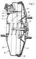
- a vacuum check valve 3 see FIG. 2. This combination is accommodated in the housing wall 4, see FIG. 1, of a vacuum servo cylinder.
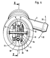
- the displacement sensor comprises a rotary potentiometer 5, see FIG. 4, which is actuated by a flexible toothed rack 6, see FIG. 2, which is guided by a telescopic device 7.
- the rack is also guided by a slide rail 8.
- the rack rotates a gear wheel 9.
- the gear wheel in turn rotates the tappet 12 of the rotary potentiometer via a driving pin 11.
- a spiral spring 13 is provided which, when the brake is released, resets all actuation elements of the displacement transducer without play.
- the outer Einküpfbund 14 of the displacement sensor 1 is oval in order to prevent rotation.
- the vacuum brake booster shown in FIG. 1 consists of the servo cylinder, which is designated in its entirety by 15, and a servo piston 16.
- the servo cylinder consists of two shells 17, 18 which are connected to one another in the region of their outer periphery.
- the servo piston 16 is designed as a diaphragm plate which is fastened in an axially movable manner in a sealing manner in the servo cylinder by means of a rolling diaphragm 19.
- FIG 1 two positions of the servo piston or the diaphragm plate are shown, which bear the reference numerals 16, 20.
- the reference number 16 designates the diaphragm plate in its retracted right position when the brake is released.
- the reference number 20 designates the position of the membrane plate in its extreme left position. With the double arrow 21, the stroke of the diaphragm plate is designated.
- a stylus is designated, which strikes the membrane plate only when braking, or in another embodiment is constantly applied.
- connection body for the vacuum connection designed as a housing for the displacement sensor, is designated by 23. 29, see FIG. 1, is a sealing plug for the connection body 23.
- the toothed rack 6 meshes with the toothed wheel 9.
- the possible directions of movement of the toothed wheel are shown in FIG. 2 by the double arrow 27.
- the Einküpfbund which is designated in its entirety with 14, has a sawtooth profile 28.
- the collar itself as shown, is oval or elliptical, which ensures that the housing 23 is secured against rotation relative to the wall of the servo cylinder.
- a vacuum check valve 3 is attached to the housing 23.
- a vacuum connection piece 2 is formed on the check valve.
- the unit consisting of a check valve and vacuum connector, is rotatable relative to the housing 23 of the displacement sensor. The rotatability is represented in FIG. 3 by arrows 30, 31 and in FIG. 4 by arrows 32, 33.
- the vacuum connection piece can be rotated, it can be easily adapted to the installation conditions specified by the car manufacturer, such as laying the vacuum line.
- the flexible rack 6 is shown in section in FIG. As explained, it is in operative connection with the gear wheel 9, see FIG. 4.
- the hub part 34 which is mounted on the shaft 10, is rotated via the driving pin 11.
- the wiper 12 is firmly connected to the hub part.
- the wiper is in physical contact with the ohmic resistor 35, which is attached to a base plate 36, which is made of electrically non-conductive material and is connected to the housing. Depending on the position of the tapper on the ohmic resistance, a certain distance of the arc-shaped ohmic resistance is effective.
- the gearwheel 9 has a further driving pin 38 which is connected to one end of the spiral spring 13.
- This coil spring acts in the sense that the stylus, as shown above, is held in abutment on the diaphragm plate via the gear and the flexible rack.
- the base plate made of non-conductive material and the ohmic resistor attached thereon are arranged in a stationary manner in the housing while the tappet is moving.
- the base plate with the ohmic resistance is moved by the gearwheel and the tappet is designed as a stationary member.
- the sensor housing according to the invention can also be designed without a vacuum check valve and without a vacuum connecting piece.
- a constructive solution is particularly useful when the vacuum check valve is to be installed in the suction line in the area of the intake manifold of the engine.
- the displacement sensor housing is then designed such that it lies practically in the contour of the cylinder of the amplifier.
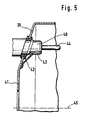
- FIG. 1 Another embodiment of the invention is shown in FIG.
- the connecting body 40 designed as a housing is arranged on a part 39 of the wall 41 of the servo cylinder in such a way that the stylus 44 executes axis-parallel movements with respect to the axis 45 of the brake booster.
- the tongue 42 shown in FIG. 5, which projects into a groove 43 of the connecting body 40, is a further possibility of securing against rotation in the case of an oblique housing and a round connecting body.
- Axially parallel movements with a round connecting body 40 can be ensured, for example, even without securing against rotation, by arranging the part 39 of the wall 41 of the servo cylinder so that it is perpendicular to the axis 45 of the brake booster.
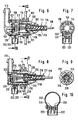
- the vacuum connection valve has a check valve 112, through which air can be drawn in via an intake duct 114 and an intake port 113 from the vacuum chamber, not shown, of the vacuum brake booster.
- the intake duct 114 is arranged in a valve housing 115.
- the displacement sensor 110 arranged in the valve housing 115 has a movable part 111 which is in contact with the membrane plate 16 shown in FIG. 1 when actuated. In the rest position of the diaphragm plate 16, there may be play between the movable part 111 and the diaphragm plate 16. When actuated, the diaphragm plate 16 is moved in the direction of the master brake cylinder (not shown) and pushes the movable part 111 into the valve housing 115.
- the movable part 111 has a first telescopic element 116 which can be moved telescopically into the housing 115 against the force of a spring 117.
- the first telescopic element 116 is guided in the housing by bearings 40.
- the first telescopic element 116 covers part of the flow cross section of the intake duct 114 and is held approximately centrally in the intake duct 114.
- the air extracted from the vacuum chamber can flow out to the intake port 113 through the annular gap formed between the first telescopic element 116 and the valve housing 115.
- the spring 117 is supported on a stop 125 formed in the housing or on a part firmly connected thereto.
- a second telescopic element 118 is arranged in the first telescopic element 116 and can be moved telescopically into the first telescopic element 116.
- the second telescopic element 118 is held in its rest position by a second spring 119.
- the second spring 119 is guided in its position by a guide pin 124.
- the second spring 119 is much harder than the first spring 117, ie it has a much higher spring constant. If a force is now exerted on the second telescopic element 118 through the membrane plate 16, the first telescopic element 116 is first pushed into the valve housing 115 against the force 117.
- a grinder 120 is attached to the first telescopic element 116. This grinder 120 is guided over a resistance track 121 when the first telescopic element 116 moves.
- the grinder 120 and at least one end of the resistance track 121 are each electrically connected to an electrical connection 122, 123.
- the electrical resistance between the electrical connections 122 and 123 thus changes.
- the current flow through the electrical connections 122, 123 or the voltage between them is then a measure of this where the grinder 120 is located on the resistance track 121.
- this allows a statement as to how far the first telescopic element 116 has been pushed into the valve housing 115, which in turn allows setbacks on the position of the diaphragm plate 16 and the brake pedal, not shown.
- the position of the grinder 120 on the resistance path 121 is a direct measure of the position of the diaphragm plate 16 in the housing of the brake booster over the range of movement of the first telescopic element 116.
- the movement of the first telescopic element 116 to the right is limited by a stop 126 formed in the valve housing 115.
- the intake port 113 is snapped into the valve housing 115, for example by a snap connection 128.
- a seal 127 is arranged between the intake port 113 and the valve housing 115, which prevents the negative pressure generated in the intake port 113 from being released by the afterflow of air from the outside or is weakened.
- the intake port 113 is arranged at an angle with respect to the intake duct 114. In the illustrated embodiment, this angle is approximately 90 °.
- the intake manifold 113 can be aligned approximately parallel to the front of the amplifier housing 4.
- the intake port 113 is rotatably arranged in the valve housing 115. Regardless of the rotational position of the valve housing 15 in the booster housing 4, the intake port 113 can therefore always be set so that it points upward, for example. It can thus be achieved that the electrical connections 22, 23 and the intake manifold 113 can be mounted in practically any angular position relative to one another.
- FIGS. 8 to 10 show a further embodiment of a vacuum connection valve, in which parts which correspond to those of FIGS. 6 and 7 are provided with reference numerals increased by 100.
- the intake connector 213 is not rotatable, but is arranged fixedly on the valve housing 215.
- the electrical connections 222, 223 on the valve housing 215 can be rotated.
- two sliding tracks 234 are provided on the surface of the valve housing 215, which extend circumferentially around the entire valve housing 215, their beginnings and their ends being connected to one another.
- An electrical connector 237 has sliding contacts 235, 236, which are connected to the electrical connections 222, 223. The sliding contacts 235, 236 grind in any angular position of the connector 237 on the two slideways and therefore ensure the electrical connection between the slideways 234 and the electrical connections 222, 223 in any angular position.
- a movable contact 233 is provided on the first telescopic element 216 and is fixedly connected to the first telescopic element 216. When the movable part 211 moves, the movable contact comes into contact with the contact surfaces 232, 231 and 230 one after the other. The contact between the movable contact and the contact surfaces can be determined electrically.
- the movable contact 233 is connected to the contact surface 231, for example, this enables a statement to be made about how far the movable part 211 has been pushed into the housing 15, and thus a statement about the movement of the diaphragm plate 16 or the brake pedal.
- the currents flowing over the contact surfaces 230, 231, 232 or the voltages falling across resistors which are connected to the contact surfaces provide information about which contact surface is currently connected to the movable contact 233. Since discrete values are determined here, these values can also be easily digitally processed.
Landscapes
- Engineering & Computer Science (AREA)
- Transportation (AREA)
- Mechanical Engineering (AREA)
- Physics & Mathematics (AREA)
- Fluid Mechanics (AREA)
- Braking Systems And Boosters (AREA)
- Regulating Braking Force (AREA)
Abstract
Claims (29)
- Amplificateur d'effort de freinage à dépression, pour système de freinage à régulation antiblocage et/ou régulation du glissement de traction, qui comprend un cylindre d'assistance (15) et un piston d'assistance (16) disposé à l'intérieur du cylindre d'assistance, un corps de raccordement (23) pour agent fluide d'assistance étant disposé dans la paroi (4) du cylindre d'assistance et la position du piston d'assistance (16) dans le cylindre d'assistance étant relevée par un dispositif de détection, caractérisé en ce que le dispositif de détection est monté au moins partiellement dans le corps de raccordement (23), de sorte que le corps de raccordement (23) est réalisé sous la forme d'un boîtier servant à au moins une partie du dispositif de détection.
- Amplificateur d'effort de freinage à dépression suivant la revendication 1, caractérisé en ce que le dispositif de détection est constitué d'un organe de palpage, qui actionne un mécanisme à engrenage, et d'une partie électrique servant à produire un signal de détecteur (partie électrique), qui est actionnée par le mécanisme à engrenage, et en ce qu'au moins une partie des moyens de guidage de l'organe de palpage, du mécanisme à engrenage et de la partie électrique est montée dans le corps de raccordement (23).
- Amplificateur d'effort de freinage à dépression suivant une ou plusieurs des revendications précédentes, caractérisé en ce que le mécanisme à engrenage comprend une crémaillère flexible (6) et une roue dentée (9) qui sont reliées de façon à coopérer entre elles.
- Amplificateur d'effort de freinage à dépression suivant une ou plusieurs des revendications précédentes, caractérisé en ce que l'organe de palpage comprend une tige de palpage (22), qui est reliée à la crémaillère flexible (6), et un dispositif télescopique (7) servant à guider la tige de palpage.
- Amplificateur d'effort de freinage à dépression suivant une ou plusieurs des revendications précédentes, caractérisé en ce qu'il est prévu un organe élastique (ressort spiral (13)), qui, par l'intermédiaire du mécanisme à engrenage, maintient le doigt de palpage (22) en butée sur le piston d'assistance (16, 20).
- Amplificateur d'effort de freinage à dépression suivant une ou plusieurs des revendications précédentes, caractérisé en ce que la partie électrique est constituée d'un potentiométre rotatif (5) qui est actionné par la roue dentée (9).
- Amplificateur d'effort de freinage à dépression suivant une ou plusieurs des revendications précédentes, caractérisé en ce qu'il est prévu, pour le potentiomètre rotatif, une plaque de base qui constitue un seul bloc avec la roue dentée.
- Amplificateur d'effort de freinage à dépression suivant une ou plusieurs des revendications précédentes, caractérisé en ce que le potentiomètre rotatif comprend une plaque de base (36), en un matériau électriquement non conducteur, sur laquelle est disposée une résistance ohmique (35), en forme d'arc de cercle (cercle non fermé), et un curseur (12) qui est en contact physique avec la résistance ohmique et qui peut exécuter un déplacement en arc de cercle vis-à-vis de la résistance ohmique.
- Amplificateur d'effort de freinage à dépression suivant une ou plusieurs des revendications précédentes, caractérisé en ce que le curseur (12) est disposé de façon à pouvoir être entraîné en rotation vis-à-vis de la plaque de base (36), avec la résistance ohmique (35) et au moyen de la roue dentée (9).
- Amplificateur d'effort de freinage à dépression suivant une ou plusieurs des revendications précédentes, caractérisé en ce que la plaque de base est disposée, avec la résistance ohmique, de façon à pouvoir être entraînée en rotation vis-à-vis de l'organe de prélèvement au moyen de la roue dentée.
- Amplificateur d'effort de freinage à dépression suivant une ou plusieurs des revendications précédentes, caractérisé en ce que la résistance ohmique est disposée sur la roue dentée.
- Amplificateur d'effort de freinage à dépression suivant une ou plusieurs des revendications précédentes, caractérisé en ce que le corps de raccordement (23), réalisé en matière plastique, est agencé sous la forme d'un boîtier dans lequel est disposé un arbre (10) commun à la roue dentée (9) et au potentiomètre rotatif (5).
- Amplificateur d'effort de freinage à dépression suivant une ou plusieurs des revendications précédentes, caractérisé en ce que le corps de raccordement (23) est réalisé sous la forme d'un boîtier dans lequel un rail (8) de glissement de la crémaillère (6) est monté.
- Amplificateur d'effort de freinage à dépression suivant une ou plusieurs des revendications précédentes, caractérisé en ce que le corps de raccordement (23) est réalisé sous la forme d'un élément de logement d'une valve antiretour de dépression (3).
- Amplificateur d'effort de freinage à dépression suivant une ou plusieurs des revendications précédentes, caractérisé en ce que le corps de raccordement (23) est réalisé sous la forme d'un élément de logement d'une tubulure de raccordement de dépression (2).
- Amplificateur d'effort de freinage à dépression suivant une ou plusieurs des revendications précédentes, caractérisé en ce que la tubulure de raccordement de dépression (2) est disposée d'une manière rotative dans le corps de raccordement (23).
- Amplificateur d'effort de freinage à dépression suivant une ou plusieurs des revendications précédentes, caractérisé en ce que le corps de raccordement (23) n'est pas réalisé avec une forme circulaire dans la zone de sa liaison avec le cylindre d'assistance (15).
- Amplificateur d'effort de freinage à dépression suivant une ou plusieurs des revendications précédentes, caractérisé en ce que le corps de raccordement (40), réalisé en forme de boîtier, est disposé sur une partie (39) de la paroi (41) du cylindre d'assistance de façon telle que le doigt de palpage (44) effectue des déplacements parallèles à l'axe (45) de l'amplificateur d'effort de freinage.
- Amplificateur d'effort de freinage à dépression suivant une ou plusieurs des revendications précédentes, caractérisé en ce que, sur son contour extérieur et dans la zone de la liaison avec l'ouverture ménagée dans la paroi du cylindre d'assistance, le corps de raccordement (23) est pourvu d'une collerette d'accrochage (14) ayant un contour extérieur (28) de préférence en forme de dents de scie et en ce qu'un bouchon élastique d'étanchéité (29) est disposé entre l'ouverture ménagée dans la paroi (4) du cylindre d'assistance et la collerette d'accrochage (14).
- Amplificateur d'effort de freinage à dépression suivant une ou plusieurs des revendications précédentes, caractérisé en ce que la roue dentée et la plaque de base, rotative, du potentiomètre rotatif sont réalisées d'une seule pièce.
- Amplificateur d'effort de freinage à dépression suivant la revendication 1, caractérisé en ce que le corps de raccordement (23) est réalisé sous la forme d'une valve de raccordement de dépression (109, 209) et comporte un conduit d'aspiration (114, 214) qui est ménagé dans un boîtier de valve (115, 215) et débouche dans une chambre de dépression et dans lequel une partie mobile (111, 211) du capteur de déplacement (110, 210) est introduite et couvre une partie de la section transversale d'aspiration.
- Amplificateur d'effort de freinage à dépression suivant la revendication 21, caractérisé en ce que la partie mobile (111, 211) est disposée d'une manière centrale dans le conduit d'aspiration (114, 214).
- Amplificateur d'effort de freinage à dépression suivant la revendication 21 ou 22, caractérisé en ce qu'il est disposé, dans la valve de raccordement de dépression (109, 209), un capteur (110, 210) qui émet un signal électrique de sortie en fonction de la position de la pièce mobile (111, 211).
- Amplificateur d'effort de freinage à dépression suivant la revendication 23, caractérisé en ce que le capteur électrique est réalisé sous la forme d'une piste de résistance (121) sur laquelle frotte un frotteur (120) entraîné par la partie mobile (111, 211).
- Amplificateur d'effort de freinage à dépression suivant la revendication 23, caractérisé en ce que le capteur électrique comprend plusieurs surfaces de contact (230, 231, 232) qui sont isolées électriquement l'une de l'autre et qui, lors d'un déplacement de la partie mobile (211), viennent successivement en contact avec un contact mobile (233) entraîné par cette partie mobile.
- Amplificateur d'effort de freinage à dépression suivant l'une des revendications 21 à 25, caractérisé en ce que la partie mobile est soumise par un premier ressort (117, 217) à une précontrainte vers sa position de repos, en ce que, dans la partie mobile (111, 211), il est disposé un élément télescopique (118, 218) qui est soumis par un second ressort (119, 219), agissant dans la même direction, à une précontrainte s'exerçant vers sa position de repos, et en ce que le second ressort (119, 219) est extrêmement plus dur que le premier ressort (117, 217).
- Amplificateur d'effort de freinage à dépression suivant l'une des revendications 21 à 26, caractérisé en ce que la valve de raccordement de dépression (109) comprend une tubulure d'aspiration (113, 213) qui fait un angle préfixé avec le conduit d'aspiration (114, 214), de sorte qu'on peut déplacer cette tubulure d'aspiration (113, 213) en rotation vis-à-vis du boîtier de valve (115, 215).
- Amplificateur d'effort de freinage à dépression suivant l'une des revendications 21 à 27, caractérisé en ce qu'il est prévu un dispositif électrique de raccordement (237) qui est fixé sur le boîtier de valve (215) et est agencé de façon que sa position de fixation puisse être déplacée en rotation vis-à-vis du boîtier de valve (215).
- Amplificateur d'effort de freinage à dépression suivant la revendication 28, caractérisé en ce que le boîtier de valve (215) comprend plusieurs anneaux de frottement (234) qui sont reliés électriquement au capteur (210) et en ce que le dispositif de raccordement (237) comprend un nombre correspondant de contacts de frottement (235, 236) prenant appui sur ces anneaux de frottement (234).
Applications Claiming Priority (4)
| Application Number | Priority Date | Filing Date | Title |
|---|---|---|---|
| DE3939978 | 1989-12-02 | ||
| DE19893939978 DE3939978A1 (de) | 1989-12-02 | 1989-12-02 | Unterdruck-bremskraftverstaerker |
| DE19904003957 DE4003957A1 (de) | 1990-02-09 | 1990-02-09 | Bremskraftverstaerker fuer bremssysteme mit antiblockier- und/oder antriebsschlupfregelung |
| DE4003957 | 1990-02-09 |
Publications (2)
| Publication Number | Publication Date |
|---|---|
| EP0456770A1 EP0456770A1 (fr) | 1991-11-21 |
| EP0456770B1 true EP0456770B1 (fr) | 1994-01-12 |
Family
ID=25887623
Family Applications (1)
| Application Number | Title | Priority Date | Filing Date |
|---|---|---|---|
| EP90914144A Expired - Lifetime EP0456770B1 (fr) | 1989-12-02 | 1990-09-05 | Servo-frein a depression pour systemes de freinage avec regulation antiblocage et/ou antipatinage a l'entrainement |
Country Status (5)
| Country | Link |
|---|---|
| US (1) | US5224410A (fr) |
| EP (1) | EP0456770B1 (fr) |
| JP (1) | JP2880288B2 (fr) |
| DE (1) | DE59004242D1 (fr) |
| WO (1) | WO1991008131A1 (fr) |
Cited By (1)
| Publication number | Priority date | Publication date | Assignee | Title |
|---|---|---|---|---|
| WO2016066122A1 (fr) * | 2014-10-29 | 2016-05-06 | Bwi (Shanghai) Co., Ltd. | Ensemble servofrein |
Families Citing this family (20)
| Publication number | Priority date | Publication date | Assignee | Title |
|---|---|---|---|---|
| DE4116779C2 (de) * | 1991-05-23 | 2000-08-10 | Continental Teves Ag & Co Ohg | Unterdruck-Bremskraftverstärker |
| US5372335A (en) * | 1992-12-18 | 1994-12-13 | Scott H. Yenzer | Aerial marker ball and method of placement |
| DE4410699C2 (de) * | 1994-03-28 | 2001-10-04 | Continental Teves Ag & Co Ohg | Hydraulische Bremsanlage für Kraftfahrzeuge |
| DE4418270A1 (de) * | 1994-05-26 | 1995-11-30 | Teves Gmbh Alfred | Verfahren zum Regeln des Bremsdruckes |
| DE4418444C2 (de) * | 1994-05-26 | 1999-01-14 | Lucas Ind Plc | Elektronisch regelbarer Bremskraftverstärker für eine Fahrzeugbremsanlage |
| ES2092365T3 (es) * | 1994-07-27 | 1996-11-16 | Lucas Ind Plc | Sistema de freno de vehiculo que tiene un servofreno controlado electronicamente. |
| WO1999026824A1 (fr) * | 1997-11-21 | 1999-06-03 | Continental Teves Ag & Co. Ohg | Dispositif de raccordement comportant un raccord pour conduite pneumatique |
| US6051897A (en) * | 1999-05-05 | 2000-04-18 | Synchro-Start Products, Inc. | Solenoid actuator with positional feedback |
| RU2166446C2 (ru) * | 1999-06-01 | 2001-05-10 | Военный автомобильный институт | Устройство для автоматического торможения буксующего колеса автотранспортного средства |
| US6595045B1 (en) | 2000-10-16 | 2003-07-22 | Veridian Engineering, Inc. | Vehicular sensors |
| WO2002076802A1 (fr) * | 2001-03-21 | 2002-10-03 | Continental Teves Ag & Co. Ohg | Servofrein comprenant un element de raccord presentant une position angulaire definie |
| KR100594613B1 (ko) * | 2001-08-13 | 2006-06-30 | 주식회사 만도 | 진공 연결파이프를 구비한 차량용 브레이크 부스터 |
| FR2830612B1 (fr) * | 2001-10-10 | 2004-01-23 | Bosch Gmbh Robert | Capteur de course, servomoteur pneumatique integrant ce capteur et installation de freinage comportant un tel servomoteur |
| FR2834252B1 (fr) * | 2001-12-31 | 2004-06-25 | Bosch Gmbh Robert | Servomoteur comportant un contacteur de feux stop integre |
| DE102004007659B4 (de) * | 2004-02-17 | 2006-02-23 | Lucas Automotive Gmbh | Bremskrafterzeuger für eine hydraulische Fahrzeugbremsanlage |
| KR100890142B1 (ko) | 2007-10-23 | 2009-03-20 | 현대자동차주식회사 | 자동차용 부스터 |
| FR2943298A1 (fr) * | 2009-03-19 | 2010-09-24 | Peugeot Citroen Automobiles Sa | Dispositif de freinage permettant l'indexation en position d'un capteur positionne sur un embout d'un raccord relie a une paroi d'un amplificateur de freinage |
| DE102010062163A1 (de) * | 2010-11-30 | 2012-05-31 | Continental Teves Ag & Co. Ohg | Vorrichtung zur Überwachung von Position und Bewegung eines Bremspedals |
| US8690462B2 (en) | 2011-12-19 | 2014-04-08 | Xerox Corporation | Flexible gear rack carriage transport in a printing apparatus |
| KR20140135999A (ko) * | 2012-03-20 | 2014-11-27 | 콘티넨탈 테베스 아게 운트 코. 오하게 | 디바이스 스프링을 갖는 제동 디바이스 |
Family Cites Families (11)
| Publication number | Priority date | Publication date | Assignee | Title |
|---|---|---|---|---|
| US3155188A (en) * | 1961-08-21 | 1964-11-03 | Gen Motors Corp | Friction feed-back speed control |
| US3970985A (en) * | 1975-07-30 | 1976-07-20 | Sage William S | Lineal controlled resistance device |
| JPS5648942U (fr) * | 1979-09-21 | 1981-04-30 | ||
| JPS58109803A (ja) * | 1981-12-23 | 1983-06-30 | Hitachi Ltd | 圧延材の形状測定装置 |
| US4771604A (en) * | 1983-07-30 | 1988-09-20 | Nippon Air Brake Co., Ltd. | Pneumatic brake booster with relay valve in the booster-cylinder-end |
| JPS60184762U (ja) * | 1984-05-18 | 1985-12-07 | 株式会社ナブコ | エアブレ−キ用空圧作動器 |
| GB2197402B (en) * | 1986-11-06 | 1990-11-14 | Teves Gmbh Alfred | Brake system |
| DE3808523A1 (de) * | 1987-09-19 | 1989-09-28 | Teves Gmbh Alfred | Bremsanlage fuer kraftfahrzeuge mit antiblockierregelung |
| WO1989010862A1 (fr) * | 1988-05-09 | 1989-11-16 | Alfred Teves Gmbh | Dispositif de reglage de la pression des freins |
| DE3815768A1 (de) * | 1988-05-09 | 1989-11-23 | Teves Gmbh Alfred | Pneumatischer bremskraftverstaerker |
| DE4020368A1 (de) * | 1990-06-27 | 1992-01-02 | Bosch Gmbh Robert | Arbeitszylinder |
-
1990
- 1990-09-05 EP EP90914144A patent/EP0456770B1/fr not_active Expired - Lifetime
- 1990-09-05 WO PCT/EP1990/001485 patent/WO1991008131A1/fr not_active Ceased
- 1990-09-05 US US07/730,942 patent/US5224410A/en not_active Expired - Fee Related
- 1990-09-05 DE DE90914144T patent/DE59004242D1/de not_active Expired - Lifetime
- 1990-09-05 JP JP2513247A patent/JP2880288B2/ja not_active Expired - Fee Related
Cited By (1)
| Publication number | Priority date | Publication date | Assignee | Title |
|---|---|---|---|---|
| WO2016066122A1 (fr) * | 2014-10-29 | 2016-05-06 | Bwi (Shanghai) Co., Ltd. | Ensemble servofrein |
Also Published As
| Publication number | Publication date |
|---|---|
| WO1991008131A1 (fr) | 1991-06-13 |
| US5224410A (en) | 1993-07-06 |
| DE59004242D1 (de) | 1994-02-24 |
| JPH04503789A (ja) | 1992-07-09 |
| EP0456770A1 (fr) | 1991-11-21 |
| JP2880288B2 (ja) | 1999-04-05 |
Similar Documents
| Publication | Publication Date | Title |
|---|---|---|
| WO1991008131A1 (fr) | Servo-frein a depression pour systemes de freinage avec regulation antiblocage et/ou antipatinage a l'entrainement | |
| EP3271223B1 (fr) | Dispositif d'actionnement pour frein de véhicule à moteur | |
| EP0670235B1 (fr) | Installation avec pédale d'accélération | |
| DE102004011622A1 (de) | Bremsbetätigungseinheit zur Betätigung einer Kraftfahrzeugbremsanlage | |
| EP0817736B1 (fr) | Systeme de freinage hydraulique pour automobile | |
| DE3435520A1 (de) | Kraftverstaerktes lenksystem fuer ein fahrzeug | |
| EP1391615B1 (fr) | Unité de piston-cylindre | |
| DE102014220358A1 (de) | Vorrichtung zur Ermittlung einer Position und/oder eines Verstellwegs eines linear verstellbaren Kolbens eines Bremssystems eines Fahrzeugs und Herstellungsverfahren für eine derartige Vorrichtung | |
| EP1654145B1 (fr) | Unite d'actionnement de frein pour actionner un systeme de freinage d'automobile | |
| DE4003957A1 (de) | Bremskraftverstaerker fuer bremssysteme mit antiblockier- und/oder antriebsschlupfregelung | |
| DE102014214095A1 (de) | Aktuator für eine elektrohydraulische Bremsanlage | |
| DE102017011435B4 (de) | Filterelement und Filtereinrichtung, insbesondere zur Gasfiltration | |
| WO1991015387A1 (fr) | Procede d'ajustement d'une mesure fonctionnelle | |
| EP1339586B1 (fr) | Dispositif capteur pour un servofrein a depression et servofrein a depression equipe dudit capteur | |
| DE4409351A1 (de) | Einrichtung zur Überwachung des Kolbenhubs eines pneumatisch betätigbaren Bremszylinders | |
| WO2004101341A2 (fr) | Module boitier d'un frein assiste | |
| DE19911892A1 (de) | Vorrichtung zur Lenkung eines Fahrzeugs | |
| DE3939978A1 (de) | Unterdruck-bremskraftverstaerker | |
| DE102012223736A1 (de) | Kolben-Zylinder-Anordnung, insbesondere zur Verwendung in einem Kupplungsbetätigungssystem in einem Kraftfahrzeug | |
| WO2013087470A1 (fr) | Capteur d'angle de rotation | |
| DE102015213828A1 (de) | Baugruppe für eine Stelleinrichtung, insbesondere eines Abgasturboladers, und Verfahren zu Herstellung einer solchen Baugruppe | |
| DE102019213058A1 (de) | Betätigungseinheit für eine hydraulisch betätigbare Bremsanlage und zugehörige Bremsanlage | |
| EP1097072A1 (fr) | Dispositif d'actionnement pour le systeme de freinage d'un vehicule a moteur | |
| DE112023004996T5 (de) | Elektrische bremsvorrichtung | |
| EP1339583A1 (fr) | Systeme de capteur pour un servofrein a depression |
Legal Events
| Date | Code | Title | Description |
|---|---|---|---|
| PUAI | Public reference made under article 153(3) epc to a published international application that has entered the european phase |
Free format text: ORIGINAL CODE: 0009012 |
|
| 17P | Request for examination filed |
Effective date: 19910624 |
|
| AK | Designated contracting states |
Kind code of ref document: A1 Designated state(s): DE FR GB |
|
| 17Q | First examination report despatched |
Effective date: 19921007 |
|
| GRAA | (expected) grant |
Free format text: ORIGINAL CODE: 0009210 |
|
| AK | Designated contracting states |
Kind code of ref document: B1 Designated state(s): DE FR GB |
|
| GBT | Gb: translation of ep patent filed (gb section 77(6)(a)/1977) |
Effective date: 19940124 |
|
| REF | Corresponds to: |
Ref document number: 59004242 Country of ref document: DE Date of ref document: 19940224 |
|
| ET | Fr: translation filed | ||
| PLBE | No opposition filed within time limit |
Free format text: ORIGINAL CODE: 0009261 |
|
| STAA | Information on the status of an ep patent application or granted ep patent |
Free format text: STATUS: NO OPPOSITION FILED WITHIN TIME LIMIT |
|
| 26N | No opposition filed | ||
| PGFP | Annual fee paid to national office [announced via postgrant information from national office to epo] |
Ref country code: GB Payment date: 20000821 Year of fee payment: 11 |
|
| PG25 | Lapsed in a contracting state [announced via postgrant information from national office to epo] |
Ref country code: GB Free format text: LAPSE BECAUSE OF NON-PAYMENT OF DUE FEES Effective date: 20010905 |
|
| PGFP | Annual fee paid to national office [announced via postgrant information from national office to epo] |
Ref country code: FR Payment date: 20020920 Year of fee payment: 13 |
|
| PG25 | Lapsed in a contracting state [announced via postgrant information from national office to epo] |
Ref country code: FR Free format text: LAPSE BECAUSE OF NON-PAYMENT OF DUE FEES Effective date: 20040528 |
|
| REG | Reference to a national code |
Ref country code: FR Ref legal event code: ST |
|
| PGFP | Annual fee paid to national office [announced via postgrant information from national office to epo] |
Ref country code: DE Payment date: 20040930 Year of fee payment: 15 |
|
| PG25 | Lapsed in a contracting state [announced via postgrant information from national office to epo] |
Ref country code: DE Free format text: LAPSE BECAUSE OF THE APPLICANT RENOUNCES Effective date: 20060301 |