EP0456788B1 - Tamis pour trieuse sous pression pour suspensions fibreuses - Google Patents
Tamis pour trieuse sous pression pour suspensions fibreuses Download PDFInfo
- Publication number
- EP0456788B1 EP0456788B1 EP90917475A EP90917475A EP0456788B1 EP 0456788 B1 EP0456788 B1 EP 0456788B1 EP 90917475 A EP90917475 A EP 90917475A EP 90917475 A EP90917475 A EP 90917475A EP 0456788 B1 EP0456788 B1 EP 0456788B1
- Authority
- EP
- European Patent Office
- Prior art keywords
- screen
- sieve
- recesses
- inlet
- outlet side
- Prior art date
- Legal status (The legal status is an assumption and is not a legal conclusion. Google has not performed a legal analysis and makes no representation as to the accuracy of the status listed.)
- Expired - Lifetime
Links
- 239000000835 fiber Substances 0.000 title claims abstract description 33
- 239000000725 suspension Substances 0.000 title claims abstract description 24
- 238000004519 manufacturing process Methods 0.000 abstract description 4
- 230000015572 biosynthetic process Effects 0.000 description 7
- 239000004745 nonwoven fabric Substances 0.000 description 4
- 230000000694 effects Effects 0.000 description 3
- 239000012535 impurity Substances 0.000 description 3
- 239000000126 substance Substances 0.000 description 2
- 238000005054 agglomeration Methods 0.000 description 1
- 230000002776 aggregation Effects 0.000 description 1
- 238000011001 backwashing Methods 0.000 description 1
- 238000005452 bending Methods 0.000 description 1
- 238000010276 construction Methods 0.000 description 1
- 238000011109 contamination Methods 0.000 description 1
- 239000000463 material Substances 0.000 description 1
- 239000002184 metal Substances 0.000 description 1
- 238000003801 milling Methods 0.000 description 1
- 230000002093 peripheral effect Effects 0.000 description 1
Images
Classifications
-
- B—PERFORMING OPERATIONS; TRANSPORTING
- B01—PHYSICAL OR CHEMICAL PROCESSES OR APPARATUS IN GENERAL
- B01D—SEPARATION
- B01D29/00—Filters with filtering elements stationary during filtration, e.g. pressure or suction filters, not covered by groups B01D24/00 - B01D27/00; Filtering elements therefor
- B01D29/11—Filters with filtering elements stationary during filtration, e.g. pressure or suction filters, not covered by groups B01D24/00 - B01D27/00; Filtering elements therefor with bag, cage, hose, tube, sleeve or like filtering elements
- B01D29/31—Self-supporting filtering elements
-
- D—TEXTILES; PAPER
- D21—PAPER-MAKING; PRODUCTION OF CELLULOSE
- D21D—TREATMENT OF THE MATERIALS BEFORE PASSING TO THE PAPER-MAKING MACHINE
- D21D5/00—Purification of the pulp suspension by mechanical means; Apparatus therefor
- D21D5/02—Straining or screening the pulp
- D21D5/16—Cylinders and plates for screens
-
- B—PERFORMING OPERATIONS; TRANSPORTING
- B01—PHYSICAL OR CHEMICAL PROCESSES OR APPARATUS IN GENERAL
- B01D—SEPARATION
- B01D2201/00—Details relating to filtering apparatus
- B01D2201/18—Filters characterised by the openings or pores
- B01D2201/184—Special form, dimension of the openings, pores of the filtering elements
Definitions
- the invention relates to a screen for pressure sorters for fiber suspensions, which have a rotor which is in particular adjacent to a lapping side of the screen for generating positive and negative pressure surges in the fiber suspensions, the screen having a shape which is rotationally symmetrical with respect to a screen axis.
- the measures for increasing the throughput mean that the forces acting on the sieve become ever greater and often cause the sieve to be destroyed rapidly, particularly as a result of cracks occurring in the screen plate.
- the wall thickness of the Sieves enlarged; this measure also lengthens the flow channels formed by the sieve openings, a consequence which has a negative effect on the throughput of the pressure sorter.
- a sieve for pressure sorters is proposed, which is composed of annular segments stacked one on top of the other in the direction of the sieve axis, each of which has a ring of slit-shaped sieve opening channels and of which two adjacent segments each define rings of recesses that differ from one another the inlet or the outlet side of the sieve extend to the sieve opening channels and taper towards the latter.
- a sieve has relatively short sieve opening channels in the flow direction and it is extremely resistant to high pressure surges generated by a rotor, it is extremely complex to manufacture and cannot particularly effectively prevent the formation of a nonwoven fabric on the inlet side of the sieve.
- a sieve for pressure sorters which has a rotor adjacent to an inlet side of the sieve, the sieve having a shape which is rotationally symmetrical to a sieve axis and the sieve wall which is integral with its wall thickness and connects the sieve opening channels with the sieve inlet side and the sieve outlet side and is provided on its inlet side with recesses into which the sieve opening channels open.
- the sieve opening channels are in the form of slots extending transversely to the sieve circumferential direction and the inlet-side recesses are in the form of boat-shaped recesses which are milled into the sieve plate and also run transversely to the sieve circumference direction, such a boat-shaped recess for each sieve opening channel is provided (Fig. 2 to 4 of EP-0042742-B).
- the sieve opening channels are circular-cylindrical bores, each of which is assigned a truncated cone-shaped recess which opens into the inlet side of the sieve and widens towards it with a relatively small opening angle (FIGS. 5 and 6) .
- the inlet-side recesses are intended to increase the throughput of the pressure sorter, which should be due to the fact that these inlet-side recesses together with the rotor rotating on the inlet side lead to turbulence which counteracts the formation of a nonwoven fabric on the inlet side of the screen.
- an unsatisfactory throughput rate can be determined, quite apart from the fact that it is quite expensive not only the individual slit-shaped sieve opening channels, but also a boat-shaped recess for each individual sieve opening channel to mill or in the second embodiment to produce a truncated cone-shaped recess on the sieve inlet side for each individual sieve opening channel.
- WO 87/03024 discloses a pressure sorter with a circular-cylindrical sieve, in which the sieve inlet side connects to the sieve outlet side and is formed as circular cylindrical bores in the sieve opening channels provided in the groove-shaped recesses provided on the sieve inlet side and the sieve outlet side, which are parallel to one another and run transversely to the sieve circumferential direction, as a result of which the efficiency of the sieve is to be improved.
- the known sieve construction has a serious disadvantage: the groove-shaped recesses on the inlet and outlet sides extending transversely to the sieve circumference lead to the formation of Lines of weakness of the screen wall that run parallel to the axis of the screen cylinder and thus to the surface lines of the screen cylinder, so that it is not only problematic to produce an absolutely rotationally symmetrical screen cylinder from a finished screen plate by bending, but these lines of weakness also lead to the risk of permanent breaks of the screen wall due to the pressure surges generated by a rotor.
- the invention was based on the object, a permanent, d. H. to create a screen with a high level of stability for a pressure screen provided with a rotor, which screen is relatively easy to manufacture and with which a specifically high throughput can be achieved.
- the sieve having a shape which is rotationally symmetrical with respect to a sieve axis and the sieve wall, which is integral over its wall thickness, is provided with recesses both on its inlet and on its outlet side, which are connected to one another by sieve opening channels, each of the inlet-side recesses extending over a plurality of sieve opening channels and being designed as a groove running transversely to the sieve circumferential direction, and the greatest width of the outlet-side recesses, measured in the outlet-side surface of the sieve wall, being at least as large as the largest width of the grooves on the inlet side, this object can be achieved according to the invention by designing a sieve such that each of the recesses on the outlet side extends only over one of the sieve opening channels.
- the recesses on the outlet side can in particular be designed as shown in US Pat. No. 3,581,903, ie they can be boat-shaped recesses.
- the sieve opening channels are bores and the recesses on the outlet side have the shape of frustoconical, in particular flat-conical, countersinks.
- the recesses provided both on the inlet and on the outlet side of the sieve allow relatively thick sheets to be used for the production of sieves according to the invention, without relatively narrow or fine sieve opening channels leading to high pressure losses on the sieve and opposing a high throughput of the pressure sorter , because the length of the sieve opening channels is considerable due to the recesses provided on both sides is reduced.
- the groove-shaped recesses provided on the inlet side lead to the desired turbulence in the fiber suspension to be sorted, as a result of which the risk of formation of fibers on the sieve inlet side is effectively countered.
- the relatively large recesses on the outlet side in conjunction with the negative pressure surges generated by the rotor, lead to a powerful backwashing effect, so that the sieve opening channels cannot be blocked.
- the outlet-side recesses which only extend over one sieve opening channel in each case, ultimately prevent the formation of lines of weakness in the sieve wall, especially if the sieve opening channels are not slit-shaped and the outlet-side recesses have the form of countersinks.
- Embodiments are particularly preferred in which the flaps on the flap side are flat, in particular a maximum of approximately 1 mm deep, since grooves of such a depth are sufficient to generate the desired turbulence and do not significantly weaken the screen wall.
- a relatively large depth of more than half the thickness of the screen wall is recommended for the recesses on the outlet side; since each sieve opening channel is assigned a separate outlet-side recess, these recesses do not weaken the sieve wall in an inadmissible manner despite their relatively large depth, although they lead to the desired short sieve opening channels. Ratios as specified in the appended claims 5 to 8 are particularly advantageous.
- the dimensioning of the recesses it should be noted that on the one hand they should be so large that the flow velocity in the region of the recesses becomes so low that the friction losses become negligibly small even with a relatively large material density, but on the other hand the screen wall through the recesses is not so is greatly weakened that the required strength of the screen would no longer be guaranteed.
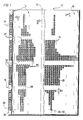
- the sieve shown in Figures 1 to 3 has a sieve wall 10 made of a metal sheet which has been bent into a circular cylinder; this sieve is intended for pressure sorters in which the fiber suspension to be sorted is introduced into the interior of the sieve cylinder formed by the sieve wall 10 and which have a rotor whose axis of rotation coincides with the axis 12 of the sieve cylinder.
- a pressure sorter is e.g. B. described and shown in EP-0042742-B.
- the fiber suspension to be sorted Since the fiber suspension to be sorted is usually fed to the sieve from above and since the rotor circulates the fiber suspension to be sorted on the inlet side of the sieve, the fiber suspension to be sorted moves helically from top to bottom along the inlet side of the sieve wall 10, which was indicated by the arrow "v" in FIG. 1.
- the inlet side of the screen was designated 14, the outlet side 16.
- the direction in which the fiber suspension passes the sieve was marked with the arrow "D" in FIGS. 1 to 4.
- 10 sieve opening channels 20 are incorporated into the sieve wall, which in the preferred embodiment shown consist of a cylindrical bore 20.
- the screen opening channels 20 are, as can clearly be seen in FIG. 1, in the sieve wall 10 according to the invention arranged in groups, each group forming a series of sieve opening channels 20 lying one behind the other in the direction of the axis 12.
- a first recess 22 is milled into the inlet side 14 of the screen wall 10, all of these recesses being approximately boat-shaped in plan view, having a triangular cross section and thus forming a groove, the width of which was designated B1.
- all of these grooves run parallel to one another and parallel to the screen cylinder axis 12.
- a recess 24 is incorporated into the screen outlet side 16 of the screen wall for each screen opening channel 20, which according to the invention is composed of a conical bore 24a and a flat-conical countersink 24b, both of which widen in the flow direction D.
- the width or the diameter of the recesses 24, namely the width B2, according to the invention is equal to or greater than the width B1.
- the thickness of the sieve wall 10 is approximately 8 mm, the grooves 22 are only 1 mm deep, and the length of the sieve opening channels 20, measured in the flow direction D, is only approximately 0.5 mm, so that the depth of the Recesses 24 and 24a, 24b is approximately 6.5 mm.
- the axes 28 of the recesses 24 on the outlet side and the axes 30 of the sieve opening channels 20 lie in the central plane 26 of the recesses 22 on the inlet side, ie in this embodiment there is no offset of the recesses and the sieve opening channels in the direction of rotation "R. "of the rotor, not shown, is provided.
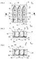
- the second embodiment shown in FIG. 4 differs from the first embodiment.
- FIG. 4 the screen wall with 110, the inlet side with 114 and the outlet side with 116, the likewise boat-shaped, inlet-side recesses with 122 and the combination of conical bores and flat-tapered recesses with outlet-side recesses with 124, which connect the recesses with each other Sieve opening channels with 120, their axes with 130, the center planes of the inlet-side recesses with 126 and the axes of the outlet
- the center planes 126 of the inlet-side recesses 122 in the direction of rotation "R" of the rotor, not shown, is offset from the axes 130 of the screen opening channels 120, while the axes 128 of the outlet-side recesses 124 coincide with the axes 130 of the screen opening channels 120.
- the offset of the recesses 122 on the inlet side, as shown in FIG. 4, is selected such that the side wall of the groove-shaped recesses 122, which increases in the direction of rotation “R” of the rotor, not shown, begins only behind the sieve opening channels 120.
- the recesses 22 and 122 on the inlet side can be machined in a simple manner by means of a profile milling cutter into the sheet forming the screen wall 10 and 110, without the strength of the screen wall being reduced too much.
Landscapes
- Chemical & Material Sciences (AREA)
- Chemical Kinetics & Catalysis (AREA)
- Engineering & Computer Science (AREA)
- Mechanical Engineering (AREA)
- Paper (AREA)
- Combined Means For Separation Of Solids (AREA)
Abstract
Claims (9)
- Tamis pour trieuses sous pression pour suspensions fibreuses, qui présentent un rotor, voisin en particulier d'un côté d'entrée (14, 114) du tamis, afin de produire des ondes de pression positives et négatives dans la suspension fibreuse, le tamis présentant une forme symétrique en rotation par rapport à un axe (12) et la paroi (10, 110) du tamis, d'une seule pièce sur son épaisseur, étant pourvue d'évidements (22, 122, 24, 124) aussi bien sur son côté d'entrée (14, 114) que sur son côté de sortie (16, 116), lesquels évidements communiquent entre eux par des canaux d'ouverture (20, 120) du tamis, chacun des évidements (22, 122) côté entrée s'étendant sur plusieurs canaux d'ouverture (20, 120) du tamis et étant conçu à la manière d'une rainure s'étendant transversalement à la direction périphérique du tamis et la plus grande largeur (B2) des évidements (24, 124) côté sortie, mesurée dans la surface de la paroi du tamis côté sortie, étant au moins aussi grande que la plus grande largeur (B1) des rainures (22, 122) côté entrée, caractérisé en ce que chacun des évidements (24 ; 124) côté sortie ne s'étend que sur l'un des canaux d'ouverture (20 ; 120) du tamis.
- Tamis selon la revendication 1, caractérisé en ce que les rainures (122) côté entrée sont décalées par rapport aux axes (130) des canaux d'ouverture (120) du tamis dans le sens de rotation (R) du rotor.
- Tamis selon les revendications 1 ou 2, caractérisé en ce que les évidements (24 ; 124) côté sortie présentent des chanfreins (24b) tronconiques.
- Tamis selon la revendication 3, caractérisé en ce que les chanfreins (24b) côté sortie sont des chanfreins coniques plats dont le cône forme à la pointe, dans la section transversale, un angle d'au moins 90°.
- Tamis selon une ou plusieurs des revendications 1 à 4, caractérisé en ce que la profondeur des rainures (22 ; 122) côté entrée est comprise entre env. 1/10 et env. 1/5 de l'épaisseur totale de la paroi (10 ; 110) du tamis.
- Tamis selon une ou plusieurs des revendications 1 à 5, caractérisé en ce que la profondeur des évidements (24a, 24b) côté sortie est égale à env. 4/5 de l'épaisseur totale de la paroi (10 ; 110) du tamis.
- Tamis selon une ou plusieurs des revendications 1 à 6, caractérisé en ce que la longueur, mesurée dans le sens de l'écoulement, des canaux d'ouverture (20 ; 120) du tamis, est au maximum égale à env. 1/10 de l'épaisseur totale de la paroi (10 ; 110) du tamis.
- Tamis selon la revendication 7, caractérisé en ce que la longueur de canaux d'ouverture (20 ; 120) du tamis est comprise entre env. 5/100 et env. 7/100 de l'épaisseur totale de la paroi (10 ; 110) du tamis.
- Tamis selon une ou plusieurs des revendications précédentes, caractérisé en ce que les évidements (24) côté sortie présentent chacun un alésage (24a) conique se raccordant au canal d'ouverture (20) du tamis, s'élargissant dans le sens d'écoulement (D), ainsi qu'un chanfrein (24b), se raccordant à cet alésage.
Priority Applications (1)
| Application Number | Priority Date | Filing Date | Title |
|---|---|---|---|
| AT90917475T ATE96863T1 (de) | 1989-12-06 | 1990-12-05 | Sieb fuer drucksortierer fuer fasersuspensionen. |
Applications Claiming Priority (2)
| Application Number | Priority Date | Filing Date | Title |
|---|---|---|---|
| DE3940334 | 1989-12-06 | ||
| DE3940334A DE3940334A1 (de) | 1989-12-06 | 1989-12-06 | Sieb fuer drucksortierer fuer fasersuspensionen |
Publications (2)
| Publication Number | Publication Date |
|---|---|
| EP0456788A1 EP0456788A1 (fr) | 1991-11-21 |
| EP0456788B1 true EP0456788B1 (fr) | 1993-11-03 |
Family
ID=6394921
Family Applications (1)
| Application Number | Title | Priority Date | Filing Date |
|---|---|---|---|
| EP90917475A Expired - Lifetime EP0456788B1 (fr) | 1989-12-06 | 1990-12-05 | Tamis pour trieuse sous pression pour suspensions fibreuses |
Country Status (5)
| Country | Link |
|---|---|
| US (1) | US5259512A (fr) |
| EP (1) | EP0456788B1 (fr) |
| CA (1) | CA2045677C (fr) |
| DE (2) | DE3940334A1 (fr) |
| WO (1) | WO1991008338A1 (fr) |
Families Citing this family (19)
| Publication number | Priority date | Publication date | Assignee | Title |
|---|---|---|---|---|
| AT398090B (de) * | 1992-05-15 | 1994-09-26 | Andritz Patentverwaltung | Vorrichtung zum abtrennen von flüssigkeit aus feststoff-flüssigkeit-mischungen mit einer feststoffrückhalteeinrichtung sowie vorrichtung in form einer schneckenpresse |
| AT398088B (de) * | 1992-11-09 | 1994-09-26 | Fehrer Textilmasch | Lochplatte für eine vorrichtung zum nadeln eines faservlieses |
| US5384044A (en) * | 1993-09-07 | 1995-01-24 | Techniweave, Inc. | Fluid separation devices and methods of making same |
| US5624560A (en) * | 1995-04-07 | 1997-04-29 | Baker Hughes Incorporated | Wire mesh filter including a protective jacket |
| US5642781A (en) * | 1994-10-07 | 1997-07-01 | Baker Hughes Incorporated | Multi-passage sand control screen |
| ATE181120T1 (de) * | 1995-02-03 | 1999-06-15 | Finckh Maschf | Drucksortierer zum sortieren von fasersuspensionen sowie sieb für einen solchen drucksortierer |
| US5598890A (en) * | 1995-10-23 | 1997-02-04 | Baker Hughes Inc. | Completion assembly |
| US5611399A (en) * | 1995-11-13 | 1997-03-18 | Baker Hughes Incorporated | Screen and method of manufacturing |
| FI100010B (fi) * | 1995-11-28 | 1997-08-15 | Ahlstrom Machinery Oy | Seulasylinteri |
| JP3396456B2 (ja) * | 2000-02-04 | 2003-04-14 | 三菱重工業株式会社 | 紙料精選装置 |
| CA2403127A1 (fr) * | 2000-02-19 | 2002-10-11 | Voith Finckh Fiber Systems Gmbh & Co. Kg | Tamis pour suspensions de fibres et son procede de production |
| US7168570B2 (en) * | 2001-10-24 | 2007-01-30 | Advanced Fiber Technologies | Screen cylinder with performance boosting configuration |
| FI118810B (fi) * | 2003-09-01 | 2008-03-31 | Anpap Oy | Sihtirakenne käytettäväksi kuitutuotteen valmistuksessa |
| SE526033C3 (sv) | 2003-11-06 | 2009-12-08 | Metso Paper Inc | Silanordning och silkorg för silning av massasuspensioner |
| US7306176B1 (en) | 2004-06-21 | 2007-12-11 | Prince Industries, Inc. | Compression assembly |
| WO2007046185A1 (fr) * | 2005-10-19 | 2007-04-26 | Arai Machinery Corporation | Élément perforé |
| SE537441C2 (sv) * | 2013-08-29 | 2015-04-28 | Bomill Ab | Trumma, en maskin som innefattar en sådan trumma, och ett förfarande för tillverkning av en sådan trumma |
| DE102016110271A1 (de) | 2015-07-10 | 2017-01-12 | Hilite Germany Gmbh | Sieb für ein Hydraulikventil und Hydraulikventil |
| CN113512897B (zh) * | 2021-06-24 | 2022-09-09 | 广东冠豪新材料研发有限公司 | 全竹浆本色牛皮纸增强交织力加工设备 |
Family Cites Families (12)
| Publication number | Priority date | Publication date | Assignee | Title |
|---|---|---|---|---|
| DE1157200B (de) * | 1962-02-08 | 1963-11-14 | Buckau Wolf Maschf R | Sieb zum Abscheiden von Feststoffen aus einem Feststoff-Fluessigkeits-Gemisch |
| DE1905832U (de) * | 1964-09-16 | 1964-12-03 | Hermann Finckh G M B H | Sichter fuer papierstoff-suspensionen. |
| DE2750499C3 (de) * | 1977-11-11 | 1982-02-04 | Hermann Finckh, Maschinenfabrik GmbH & Co, 7417 Pfullingen | Sortierer für Fasersuspension |
| US4276159A (en) * | 1980-06-19 | 1981-06-30 | The Black Clawson Company | Apparatus for screening paper fiber stock |
| DE3265205D1 (en) * | 1982-05-04 | 1985-09-12 | Finckh Maschf | Screen drum for a pulp stock screening apparatus |
| FI67588C (fi) * | 1983-01-26 | 1985-04-10 | Ahlstroem Oy | Silplaot |
| US4717471A (en) * | 1985-09-05 | 1988-01-05 | The Black Clawson Company | Apparatus for screening paper fiber stock |
| SE450711B (sv) * | 1985-11-14 | 1987-07-20 | Besam Ag | Silorgan |
| DE3663700D1 (en) * | 1986-07-15 | 1989-07-06 | Finckh Maschf | Pressure separator |
| FR2613389A1 (fr) * | 1987-04-06 | 1988-10-07 | Lamort E & M | Perfectionnement aux tamis pour epurateurs de pate a papier |
| FI77279C (fi) * | 1987-04-30 | 1989-02-10 | Ahlstroem Oy | Foerfarande och anordning foer behandling av fibersuspension. |
| US4986900A (en) * | 1989-04-04 | 1991-01-22 | A. Ahlstrom Corporation | Sectional screen cylinder |
-
1989
- 1989-12-06 DE DE3940334A patent/DE3940334A1/de not_active Withdrawn
-
1990
- 1990-12-05 DE DE90917475T patent/DE59003364D1/de not_active Expired - Fee Related
- 1990-12-05 EP EP90917475A patent/EP0456788B1/fr not_active Expired - Lifetime
- 1990-12-05 WO PCT/DE1990/000942 patent/WO1991008338A1/fr not_active Ceased
- 1990-12-05 US US07/743,344 patent/US5259512A/en not_active Expired - Fee Related
- 1990-12-05 CA CA002045677A patent/CA2045677C/fr not_active Expired - Fee Related
Also Published As
| Publication number | Publication date |
|---|---|
| DE3940334A1 (de) | 1991-06-13 |
| US5259512A (en) | 1993-11-09 |
| CA2045677C (fr) | 2001-08-21 |
| EP0456788A1 (fr) | 1991-11-21 |
| WO1991008338A1 (fr) | 1991-06-13 |
| DE59003364D1 (de) | 1993-12-09 |
| CA2045677A1 (fr) | 1991-06-07 |
Similar Documents
| Publication | Publication Date | Title |
|---|---|---|
| EP0456788B1 (fr) | Tamis pour trieuse sous pression pour suspensions fibreuses | |
| DE3400423C3 (de) | Verwendung einer von einer Fasersuspension überströmbaren Lochplatte zum Klassieren | |
| DE102007020325B3 (de) | Verfahren zur Herstellung eines Siebes für die Behandlung von zur Papiererzeugung geeigneten Faserstoffsuspensionen | |
| DE69217237T2 (de) | Führungsteil für einen stoffauflauf | |
| DE69311898T3 (de) | Vorrichtung zur behandlung von fasersuspensionen | |
| DE2522349A1 (de) | Feinmuehle fuer holzschliff geringer konsistenz | |
| DE4000248C2 (fr) | ||
| EP2516733A1 (fr) | Procédé et dispositif de tamisage pour le tamisage d'une suspension de matière fibreuse | |
| DE69314034T2 (de) | Siebvorrichtung für faserbrei | |
| EP0146641A1 (fr) | Tamis à trier pour suspensions de fibres de pâte | |
| EP0093187B1 (fr) | Tambour de tamisage pour les appareils d'épuration des pâtes à papier | |
| EP1895046B1 (fr) | Dépulpeuse dotée d'une plaque perforée avec un maximum de bords de défibrage | |
| DE19911884A1 (de) | Drucksortierer zum Sieben einer Papierfaserstoffsuspension und Siebräumer für einen solchen | |
| AT395325B (de) | Vorrichtung zum auftrennen einer zellulosefaserbrei-suspension | |
| EP0805890B1 (fr) | Trieuse sous pression de suspensions de fibres et crible pour ces trieuses sous pression | |
| DE3015370C2 (de) | Siebkorb für Sortierer der Papierindustrie | |
| EP0175053A2 (fr) | Foret à chanfreiner conique | |
| DE4432842C2 (de) | Verfahren zum Ausbringen unerwünschter Feststoffpartikel aus einer wässerigen Faserstoffsuspension sowie Vorrichtung zu seiner Ausführung | |
| EP0807709B1 (fr) | Dispositif pour l'épuration d'une suspension fibreuse | |
| DE60028188T2 (de) | Siebvorrichtung | |
| EP0905309B1 (fr) | Tamis et appareil de tamisage sous pression pour suspensions fibreuses | |
| DE3448571C2 (de) | Siebplatte für Fasersuspensionen | |
| DE19747653C2 (de) | Sieb für Faserstoffsuspensionen | |
| AT221921B (de) | Aufbereitungsvorrichtung für breiige Materialien, insbesondere Rohstoff zur Papierherstellung | |
| AT406392B (de) | Einlassstauvorrichtung für eine maschine zur verarbeitung von fasersuspension |
Legal Events
| Date | Code | Title | Description |
|---|---|---|---|
| PUAI | Public reference made under article 153(3) epc to a published international application that has entered the european phase |
Free format text: ORIGINAL CODE: 0009012 |
|
| 17P | Request for examination filed |
Effective date: 19910806 |
|
| AK | Designated contracting states |
Kind code of ref document: A1 Designated state(s): AT DE FR GB IT NL SE |
|
| 17Q | First examination report despatched |
Effective date: 19930414 |
|
| GRAA | (expected) grant |
Free format text: ORIGINAL CODE: 0009210 |
|
| AK | Designated contracting states |
Kind code of ref document: B1 Designated state(s): AT DE FR GB IT NL SE |
|
| PG25 | Lapsed in a contracting state [announced via postgrant information from national office to epo] |
Ref country code: SE Effective date: 19931103 |
|
| REF | Corresponds to: |
Ref document number: 96863 Country of ref document: AT Date of ref document: 19931115 Kind code of ref document: T |
|
| ITF | It: translation for a ep patent filed | ||
| REF | Corresponds to: |
Ref document number: 59003364 Country of ref document: DE Date of ref document: 19931209 |
|
| ET | Fr: translation filed | ||
| GBT | Gb: translation of ep patent filed (gb section 77(6)(a)/1977) |
Effective date: 19940126 |
|
| PLBE | No opposition filed within time limit |
Free format text: ORIGINAL CODE: 0009261 |
|
| STAA | Information on the status of an ep patent application or granted ep patent |
Free format text: STATUS: NO OPPOSITION FILED WITHIN TIME LIMIT |
|
| 26N | No opposition filed | ||
| REG | Reference to a national code |
Ref country code: GB Ref legal event code: IF02 |
|
| PGFP | Annual fee paid to national office [announced via postgrant information from national office to epo] |
Ref country code: FR Payment date: 20020927 Year of fee payment: 13 |
|
| PGFP | Annual fee paid to national office [announced via postgrant information from national office to epo] |
Ref country code: GB Payment date: 20021204 Year of fee payment: 13 Ref country code: AT Payment date: 20021204 Year of fee payment: 13 |
|
| PGFP | Annual fee paid to national office [announced via postgrant information from national office to epo] |
Ref country code: NL Payment date: 20021223 Year of fee payment: 13 |
|
| PGFP | Annual fee paid to national office [announced via postgrant information from national office to epo] |
Ref country code: DE Payment date: 20021230 Year of fee payment: 13 |
|
| PG25 | Lapsed in a contracting state [announced via postgrant information from national office to epo] |
Ref country code: GB Free format text: LAPSE BECAUSE OF NON-PAYMENT OF DUE FEES Effective date: 20031205 Ref country code: AT Free format text: LAPSE BECAUSE OF NON-PAYMENT OF DUE FEES Effective date: 20031205 |
|
| PG25 | Lapsed in a contracting state [announced via postgrant information from national office to epo] |
Ref country code: NL Free format text: LAPSE BECAUSE OF NON-PAYMENT OF DUE FEES Effective date: 20040701 Ref country code: DE Free format text: LAPSE BECAUSE OF NON-PAYMENT OF DUE FEES Effective date: 20040701 |
|
| GBPC | Gb: european patent ceased through non-payment of renewal fee |
Effective date: 20031205 |
|
| PG25 | Lapsed in a contracting state [announced via postgrant information from national office to epo] |
Ref country code: FR Free format text: LAPSE BECAUSE OF NON-PAYMENT OF DUE FEES Effective date: 20040831 |
|
| NLV4 | Nl: lapsed or anulled due to non-payment of the annual fee |
Effective date: 20040701 |
|
| REG | Reference to a national code |
Ref country code: FR Ref legal event code: ST |
|
| PG25 | Lapsed in a contracting state [announced via postgrant information from national office to epo] |
Ref country code: IT Free format text: LAPSE BECAUSE OF NON-PAYMENT OF DUE FEES;WARNING: LAPSES OF ITALIAN PATENTS WITH EFFECTIVE DATE BEFORE 2007 MAY HAVE OCCURRED AT ANY TIME BEFORE 2007. THE CORRECT EFFECTIVE DATE MAY BE DIFFERENT FROM THE ONE RECORDED. Effective date: 20051205 |