EP0456828A1 - Steuerungsverfahren für den antrieb eines motortyps änderlicher reluktanz - Google Patents
Steuerungsverfahren für den antrieb eines motortyps änderlicher reluktanz Download PDFInfo
- Publication number
- EP0456828A1 EP0456828A1 EP90917086A EP90917086A EP0456828A1 EP 0456828 A1 EP0456828 A1 EP 0456828A1 EP 90917086 A EP90917086 A EP 90917086A EP 90917086 A EP90917086 A EP 90917086A EP 0456828 A1 EP0456828 A1 EP 0456828A1
- Authority
- EP
- European Patent Office
- Prior art keywords
- salient pole
- rotor
- motor
- rotary position
- excitation
- Prior art date
- Legal status (The legal status is an assumption and is not a legal conclusion. Google has not performed a legal analysis and makes no representation as to the accuracy of the status listed.)
- Withdrawn
Links
Images


Classifications
-
- H—ELECTRICITY
- H02—GENERATION; CONVERSION OR DISTRIBUTION OF ELECTRIC POWER
- H02P—CONTROL OR REGULATION OF ELECTRIC MOTORS, ELECTRIC GENERATORS OR DYNAMO-ELECTRIC CONVERTERS; CONTROLLING TRANSFORMERS, REACTORS OR CHOKE COILS
- H02P25/00—Arrangements or methods for the control of AC motors characterised by the kind of AC motor or by structural details
- H02P25/02—Arrangements or methods for the control of AC motors characterised by the kind of AC motor or by structural details characterised by the kind of motor
- H02P25/08—Reluctance motors
- H02P25/092—Converters specially adapted for controlling reluctance motors
- H02P25/0925—Converters specially adapted for controlling reluctance motors wherein the converter comprises only one switch per phase
-
- Y—GENERAL TAGGING OF NEW TECHNOLOGICAL DEVELOPMENTS; GENERAL TAGGING OF CROSS-SECTIONAL TECHNOLOGIES SPANNING OVER SEVERAL SECTIONS OF THE IPC; TECHNICAL SUBJECTS COVERED BY FORMER USPC CROSS-REFERENCE ART COLLECTIONS [XRACs] AND DIGESTS
- Y02—TECHNOLOGIES OR APPLICATIONS FOR MITIGATION OR ADAPTATION AGAINST CLIMATE CHANGE
- Y02P—CLIMATE CHANGE MITIGATION TECHNOLOGIES IN THE PRODUCTION OR PROCESSING OF GOODS
- Y02P80/00—Climate change mitigation technologies for sector-wide applications
- Y02P80/10—Efficient use of energy, e.g. using compressed air or pressurized fluid as energy carrier
Definitions
- the present invention relates to a method for drivingly controlling a variable reluctance type motor, and more particularly, to a drive control method of this kind capable of improving the efficiency of a motor.
- a variable reluctance type motor which comprises a stator having a plurality of salient poles around which windings are wound and a rotor having a plurality of salient poles, is so arranged as to rotate the rotor by attracting a rotor salient pole near an excited stator salient pole towards the stator salient pole by a magnetic attraction force caused by the excited stator salient pole.
- the rotary torque applied to the rotor acts in a direction to reduce the magnetic resistance between the stator salient pole and the rotor salient pole, irrespective of the direction of a current flowing in the stator winding.
- the rotary torque acting in the direction of the rotor rotation is applied to the rotor from an instant at which the rotor salient pole starts to face the excited stator salient pole until an instant at which the rotor salient pole is brought to completely face the stator salient pole.
- the rotary torque acting in a direction opposite to the rotation direction of the rotor is applied to the rotor salient pole until the rotor salient pole starts to be deviated from a state where it faces the stator salient pole.
- the rotary torque acting in the rotor rotation direction or the counterclockwise direction is applied to a rotor salient pole 21a from the time when the leading edge 21a', as viewed in the rotor rotation direction, of the rotor salient pole 21a has reached a position on an extension of the leading edge 20A' of an excited stator salient pole 20A of A-phase and hence the rotor salient pole 21a has reached that rotary position (electrical angle of 0 degree) of the rotor which is shown in Fig.
- the rotary torque acting in a direction opposite to the rotor rotation direction or the clockwise direction is applied to the rotor salient pole 21a until the trailing edge 21a'' of the rotor salient pole 21a reaches a position on the extension (electrical angle of 360 degrees) of the trailing edge 20A'' of the stator salient pole 20A and hence the rotor salient pole 21a starts to be deviated from a state where it faces the stator salient pole 20A.
- the leading edge 21d' of the next rotor salient pole 21d reaches a position on the extension of the leading edge 20A' of the stator salient pole 20A, so that the rotor salient pole 21d starts to face the stator salient pole 20A.
- the acting direction of the rotary torque caused when a stator salient pole of a certain phase is excited is determined in dependence on the rotary position (electrical angle) of the rotor representing the positional relation between the stator salient pole and the rotor salient pole.
- the respective stator salient poles are sequentially excited in a desired order for a desired period of time in accordance with the rotary position of the rotor. For example, in an example shown in Figs.
- an A-phase stator winding (not shown) wound around the stator salient pole 20A is energized in a rotor rotation region represented by an electrical angle region of 0 to 180 degrees.
- the A-phase stator winding is energized in a rotor rotation region indicated by an electrical angle region of 180 to 360 degrees.
- An object of the present invention is to provide a method for drivingly controlling a variable reluctance type motor, which is capable of reducing or preventing generation of a disturbance torque acting to rotate a rotor in a direction opposite to a desired rotation direction, thereby improving motor efficiency.
- a drive control method for use in a variable reluctance type motor which includes a stator having a plurality of salient poles around which windings are wound and a rotor having a plurality of salient poles, the motor being driven in that motor driving mode which is determined in dependence on a difference between a command value of a motor driving parameter and an actual value thereof and which is one of an acceleration mode where a torque acting in a rotation direction of the motor is generated and a deceleration mode where a torque acting in a direction opposite to the rotor rotation direction is generated.
- the drive control method comprises the steps of: (a) starting excitation of the winding of a to-be-excited stator salient pole when a rotor salient pole near the to-be-excited stator salient pole has reached a first predetermined rotary position which is determined in dependence on the motor driving mode, so as to generate a desired torque acting in a rotation direction suited to the motor driving mode; and (b) interrupting the excitation started in the step (a) when the rotor salient pole has reached a third predetermined rotary position short of a second predetermined rotary position which cooperates with the first predetermined rotary position to define a predetermined rotary angle region where the desired torque is generated by an electric current flowing in the winding associated with the step (a), so as to prevent an electric current from flowing in the winding in a region other than the predetermined rotary angle region.
- a determination to the effect that the rotor salient pole has reached the first predetermined rotary position is made when the rotor salient pole starts to face the stator salient pole.
- a determination to the effect that the rotor salient pole has reached the first predetermined position is made when the rotor salient pole is brought to completely face the stator salient pole.
- the second predetermined rotary position in the acceleration mode is set such that the rotor salient pole will completely face the stator salient pole at that rotary position
- the second predetermined rotary position in the deceleration mode is set such that the rotor salient pole will start to be deviated at that rotary position from a state where it faces the stator salient pole.
- the third predetermined rotary position is set in dependence on the inductance of the winding. Further, a motor rotation speed is used as the motor driving parameter, and either one of the acceleration mode and the deceleration mode is selected in accordance with the difference between a command value of the motor rotation speed and an actual value thereof. More preferably, the excitation of the winding of the next stator salient pole is started before the third predetermined rotary position is reached.
- excitation of the winding of the stator salient pole is started when the rotor salient pole has reached the first predetermined rotary position determined in dependence on the motor driving mode, and the excitation is interrupted when the rotor has reached the third predetermined rotary position short of the second predetermined rotary position which cooperates with the first predetermined rotary position to define the predetermined rotary angle region where a desired torque acting in the rotation direction suited to the motor driving mode is generated by an electric current flowing in the winding. Therefore, an electric current caused by the inductance of the winding to flow in the winding after the interruption of the excitation is significantly reduced or extinguished before a disturbance torque acting in a direction opposite to the intended acting direction is generated by the above electric current. As a result, no energy is consumed to cancel the disturbance torque, whereby the motor efficiency can be improved.
- excitation of the winding of the next stator salient pole is started before the third predetermined rotary position is reached, so that the rotary torque can be continuously generated to smoothly rotate the motor.
- one of four excitation patterns is selected according to whether the motor is to be rotated in a clockwise direction or counterclockwise direction and whether a motor driving mode, which is determined in dependence on the difference between a command value of a motor driving parameter (e.g., motor rotation speed) and an actual value thereof, is either an acceleration mode for generating a torque acting in the motor rotation direction or a deceleration mode for generating a torque acting in a direction opposite to the motor rotation direction.
- a motor driving mode which is determined in dependence on the difference between a command value of a motor driving parameter (e.g., motor rotation speed) and an actual value thereof, is either an acceleration mode for generating a torque acting in the motor rotation direction or a deceleration mode for generating a torque acting in a direction opposite to the motor rotation direction.
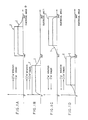
- an excitation pattern shown in Fig. 1A is selected.
- this excitation pattern when the rotor 21 has reached a rotary position (Fig. 4B) indicated by an electrical angle of 180 degrees and hence the rotor salient pole 21a is brought to completely face the stator salient pole 20A, a determination to the effect that the starting point of the excitation section T is reached is made, so that excitation of the winding (not shown) of the stator salient pole 20A is started. As a result, a torque acting in the clockwise direction which is opposite to the motor rotation direction is generated, so that the motor is deceleratingly operated.
- the excitation of the winding is interrupted slightly before the rotor salient pole 21a starts to be deviated from a state where it faces the stator salient pole 20A.
- an electric current I flows in the winding because of the presence of the inductance of the winding. Therefore, the excitation section T, particularly the termination end thereof, is properly set, so that the winding current I assumes a value of zero or close to zero when the rotor salient pole 21a has reached that rotary position which is represented by an electrical angle of 360 degrees and which corresponds to the rotary position of the rotor salient pole 21b shown in Fig.
- the stator salient pole 20A is de-energized when the facing state between the rotor salient pole 21a and the stator salient pole 20A starts to be broken, that is, when the next rotor salient pole 21d has reached a rotary position corresponding to the rotary position of the rotor salient pole 21a shown in Fig. 4A. Therefore, the rotor salient pole 21d will not be magnetically attracted by the stator salient pole 20A, and no torque acting in the counterclockwise direction is generated, so that the deceleration operation of the motor will not be disturbed.
- an excitation pattern shown in Fig. 1B is selected.
- the rotor 21 has reached a rotary position of Fig. 4A indicated by an electrical angle of 0 degree, and the rotor salient pole 21a starts to face the stator salient pole 20A, excitation of the winding of the stator salient pole 20A is started.
- a torque acting in the counterclockwise direction which is the same as the motor rotation direction, is generated, whereby the motor is operated acceleratingly.
- the excitation of the winding is interrupted slightly before the rotor salient pole 21a is brought to completely face the stator salient pole 20A.
- the winding current I assumes a value of zero or close to zero when the rotor salient pole 21a has reached a rotary position indicated by an electrical angle of 180 degrees and corresponding to the rotary position shown in Fig. 4B, and hence the rotor salient pole 21a is brought to completely face the stator salient pole 20A.
- the stator salient pole 20A is de-energized when the rotor salient pole 21a starts to be further rotated in the counterclockwise direction. Therefore, the rotor salient pole 21a will not be magnetically attracted by the stator salient pole 20A, and no torque acting in the clockwise direction and disturbing the accelerating operation is generated.
- excitation of the winding of the stator salient pole 20A is started when the rotor 21 has reached a rotary position of Fig. 4A indicated by an electrical angle of 360 degrees and hence the rotor salient pole 21b starts to face the stator salient pole 20A, so that a torque acting in the clockwise direction which is the same as the motor rotation direction is generated, whereby the motor is acceleratingly operated.
- the excitation of the winding is interrupted slightly before the rotor salient pole 21b is brought to completely face the stator salient pole 20A.
- the winding current I assumes a value of zero or closed to zero when the rotor salient pole 21b has reached a rotary position indicated by an electrical angle of 180 degrees and corresponding to the rotary position of the rotor 21a shown in Fig. 4B, with the rotor salient pole 21a brought to completely face the stator salient pole 20A.
- the stator salient pole 20A is de-energized when the rotor salient pole 21b starts to be further rotated in the clockwise direction. Therefore, the rotor salient pole 21b will not be magnetically attracted by the stator salient pole 20A, and hence no torque acting in the counterclockwise direction and disturbing the accelerating operation is generated.
- stator salient pole 20A is de-energized when the facing state between the rotor salient pole 21a and the stator salient pole 20A starts to be broken, that is, when the next rotor salient pole 21b has reached the rotary position shown in Fig. 4A and starts to face the stator salient pole 20A. Therefore, the rotor salient pole 21b will not be magnetically attracted by the stator salient pole 20A, and no torque acting in the clockwise direction and disturbing the deceleration operation is generated.
- the above four excitation patterns are determined, for instance, by actual measurements conducted while the motor is being rotated at a rotational speed at the time of use of the motor.
- the electrical angles of the rotor at the excitation starting time and excitation interruption time are determined in such a manner that the difference between the electrical angles of the rotor at the excitation starting time and excitation interruption time never be smaller than an electrical angle derived by dividing the electrical angle of 360 degrees by the number of motor phases.
- the present embodiment is so arranged as to control the excitation of the stator winding of each phase in accordance with that corresponding one of the four excitation patterns which is determined in dependence on the motor rotation direction and the motor driving mode.
- the excitation section T of each phase of the motor is set to have an electrical angle of 135 degrees. That is, the excitation is interrupted when the rotor has rotated through an electrical angle of 135 degrees after start of the excitation.
- the electrical angle shown in the drawing is associated with the A-phase excitation pattern, and the B- and C-phases are shifted with respect to the A-phase by 120 and 240 degrees, respectively.
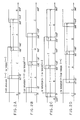
- the excitation of the A-, B- and C-phase stator windings is controlled in accordance with the excitation pattern of Fig. 2A.
- the excitation of the A-phase stator winding is started to excite the A-phase stator salient pole, whereby a torque acting in the clockwise direction which is opposite to the motor rotation direction is generated, and the motor is operated deceleratingly.
- the C-phase excitation started as will be described later is interrupted.
- a second rotor salient pole another rotor salient pole (hereinafter referred to as a second rotor salient pole) is brought to completely face the B-phase stator salient pole.
- the B-phase excitation is started to excite the stator salient pole so that a torque acting in the clockwise direction to decelerate the motor is generated.
- the A-phase excitation is interrupted. Even after the interruption of excitation, an electric current is caused to continuously flow in the A-phase stator winding due to the presence of the inductance of the winding, whereby a torque which acts to decelerate the motor is generated.
- the rotor has reached the rotary position indicated by an electrical angle of 360 degrees or a position in the vicinity of that rotary position, the winding current is extinguished, thereby preventing generation of a torque which accelerates the motor.
- the A-phase excitation is started at that rotor rotary position (an electrical angle of 0 degree) at which the rotor salient pole starts to face the A-phase stator salient pole, whereas the A-phase excitation is interrupted at that rotary position (an electrical angle of 135 degrees) which is short, by an electrical angle of 45 degrees, of that rotor rotary position (an electrical angle of 180 degrees) at which the rotor salient pole completely faces the A-phase stator salient pole.
- the B-phase excitation which has been started at the rotary position (an electrical angle of 120 degrees) at which the rotor salient pole starts to face the B-phase stator salient pole is interrupted at the rotary position (an electrical angle of 255 degrees) which is short, by an electrical angle of 45 degrees, of the rotary position at which the rotor salient pole completely faces the B-phase stator salient pole.
- the C-phase excitation is effected in a rotor rotary angle region corresponding to an electrical angle region of 240 to 15 degrees.
- the torque acting in the counterclockwise direction is applied to the rotor with the excitation of the individual phases, whereas the winding current caused to flow after the interruption of excitation is rendered to be extinguished before it acts to generate a substantial torque exerting in the clockwise direction.
- the A-, B- and C-phase excitation operations are started at those rotary positions (electrical angles of 360 degrees, 120 degrees and 240 degrees) at which the rotor salient pole starts to face the A-, B- or C-phase stator salient poles as shown in Fig. 2C, so that a torque acting in the clockwise direction to accelerate the motor is generated by the excitation.
- the excitation is interrupted when the rotor is rotated by a rotation angle, corresponding to the excitation section T of an electrical angle of 135 degrees, to reach the rotary position (an electrical angle of 225 degrees, 345 degrees or 105 degrees) corresponding to the termination end of the excitation section T.
- a winding current caused to flow after the interruption of excitation is extinguished before it generates a substantial torque acting in the counterclockwise direction.
- the A-, B- and C-phase excitation operations are started at the respective rotor rotary positions (electrical angles of 180 degrees, 300 degrees and 60 degrees) at which the rotor salient pole completely faces the A-, B- or C-phase stator salient poles as shown in Fig. 2D, and a torque acting in the counterclockwise direction is generated by the excitation so that the motor is decelerated.
- the excitation is interrupted when the rotor is rotated by a rotation angle of an electrical angle of 135 degrees to reach the rotary position (an electrical angle of 45 degrees, 165 degrees or 285 degrees) corresponding to the termination end of the excitation section T.
- a winding current caused to flow after the interruption of excitation is extinguished before it generates a substantial torque in the clockwise direction.
- the controller comprises A-, B- and C-phase function generators 8A, 8B and 8C each of which includes a read only memory (ROM), not shown, storing therein four types of excitation patterns (Figs. 2A to 2D).
- Each of the excitation patterns consists of function signal values respectively set for each rotor electrical angle region, and those excitation patterns stored in the ROMs which correspond to one another are different in phase from one another by an electrical angle of 120 degrees.
- the controller further comprises a frequency-to-voltage converter 9 for converting the frequency at which A- or B-phase feedback pulses are sequentially delivered from a pulse coder 7 mounted on a 3-phase variable reluctance type motor 6 with rotation of the motor into a voltage representative of the actual motor speed, and a speed loop compensation circuit 1 for amplifying the difference (speed deviation) between a speed command Vc supplied from a host controller, not shown, and an output of the converter 9, to thereby generate a torque command Tc.
- a frequency-to-voltage converter 9 for converting the frequency at which A- or B-phase feedback pulses are sequentially delivered from a pulse coder 7 mounted on a 3-phase variable reluctance type motor 6 with rotation of the motor into a voltage representative of the actual motor speed
- a speed loop compensation circuit 1 for amplifying the difference (speed deviation) between a speed command Vc supplied from a host controller, not shown, and an output of the converter 9, to thereby generate a torque command Tc.
- Each of the function generators 8A to 8C which is connected to the pulse coder 7 and the compensation circuit 1, is arranged to determine the rotation direction of the motor in accordance with the generation order of the A- and B-phase feedback pulses, and determine the motor driving mode in accordance with the positive or negative sign of the torque command Tc. Further, each function generator is arranged to generate that one of the function signal values, constituting the predetermined excitation patterns selected in accordance with the results of both the determinations, which corresponds to an actual rotor electrical angle ⁇ represented by the feedback pulses from the pulse coder 7.
- the controller comprises multipliers 2A to 2C for multiplying the function signal value from a corresponding one of the function generators 8A to 8C by the torque command Tc from the compensation circuit 1 to generate current commands ir(A) to ir(C), current detectors 5A to 5C, current loop compensation circuits 3A to 3C for respectively amplifying differences (current deviations) between corresponding ones of actual currents ic(A) to ic(C) detected by the current detectors and the current commands ir(A) to ir(C) to generate voltage commands er(A) to er(C), and power amplifiers 4A to 4C, each comprised of a PWM inverter and the like, for respectively converting the voltage commands er(A) to er(C) into voltages er'(A) to er'(C) applied to the individual phases of the motor 6.
- symbols G1(S) and G2(S) respectively denote the transfer function of the speed loop compensation circuit 1 and the transfer function of each of the current loop compensation circuits 3A to 3C
- a symbol G3 denotes the gain of each of the power amplifiers 4A to 4C.
- the generation frequency of the A- or B-phase feedback pulses sequentially generated from the pulse coder 7 with rotation of the motor 6 is converted, in the frequency/voltage converter 9, into a voltage representative of an actual motor speed. Then, in the speed loop compensation circuit 1, a torque command Tc is created in accordance with the deviation between the speed command Vc from the host controller and an output of the converter 9.
- Each of the function generators 8A to 8C determines the motor rotation direction and the motor driving mode on the basis of the generation order of the A- and B-phase feedback pulses and the sign of the torque command Tc, and selects one of the four types of excitation patterns shown in Figs. 2A to 2D in accordance with the results of these determinations.
- each of the function generators 8A to 8C selects the excitation pattern of Fig. 2A and then supplies that one of the function signal values constructing the thus selected excitation pattern which corresponds to an actual motor electrical angle ⁇ represented by the feedback pulses from the pulse coder 7.
- the current commands ir(A) to ir(C) are derived in the multipliers 2A to 2C on the basis of the function signal values from the function generators 8A to 8C and the torque command Tc, and actual currents ic(A) to ic(C) are detected by means of the current detectors 5A to 5C.
- the voltage commands er(A) to er(C) derived in the loop compensation circuits 3A to 3C on the basis of the current commands and the actual currents are converted into voltage commands er(A) to er(C) in the power amplifiers 4A to 4C and then applied to the individual phases of the motor.
- a proper excitation pattern is selected in accordance with the speed command Vc and the feedback pulses, and function signal values constructing the selected excitation pattern are sequentially read out with rotation of the motor and supplied for the motor control.
- the motor 6 is driven in the acceleration mode or deceleration mode, so that the motor 6 is rotated in a desired direction at a desired speed.
Landscapes
- Engineering & Computer Science (AREA)
- Power Engineering (AREA)
- Control Of Electric Motors In General (AREA)
- Synchronous Machinery (AREA)
Applications Claiming Priority (2)
| Application Number | Priority Date | Filing Date | Title |
|---|---|---|---|
| JP1303255A JPH03169289A (ja) | 1989-11-24 | 1989-11-24 | 可変リラクタンス型モータの駆動制御方法 |
| JP303255/89 | 1989-11-24 |
Publications (2)
| Publication Number | Publication Date |
|---|---|
| EP0456828A1 true EP0456828A1 (de) | 1991-11-21 |
| EP0456828A4 EP0456828A4 (en) | 1992-11-04 |
Family
ID=17918752
Family Applications (1)
| Application Number | Title | Priority Date | Filing Date |
|---|---|---|---|
| EP19900917086 Withdrawn EP0456828A4 (en) | 1989-11-24 | 1990-11-21 | Drive control method for variable reluctance type motor |
Country Status (4)
| Country | Link |
|---|---|
| US (1) | US5281903A (de) |
| EP (1) | EP0456828A4 (de) |
| JP (1) | JPH03169289A (de) |
| WO (1) | WO1991008611A1 (de) |
Cited By (1)
| Publication number | Priority date | Publication date | Assignee | Title |
|---|---|---|---|---|
| EP0923191A1 (de) * | 1997-12-12 | 1999-06-16 | Switched Reluctance Drives Limited | Kommutationsregler |
Families Citing this family (8)
| Publication number | Priority date | Publication date | Assignee | Title |
|---|---|---|---|---|
| US5563488A (en) * | 1992-09-24 | 1996-10-08 | Switched Reluctance Drives Limited | Control of switched reluctance machines |
| JPH06261509A (ja) * | 1993-03-04 | 1994-09-16 | Akira Ishizaki | リラクタンス形回転機 |
| JP3268573B2 (ja) * | 1994-04-25 | 2002-03-25 | アイシン精機株式会社 | スイッチドレラクタンスモ−タの制御装置 |
| US5717592A (en) * | 1994-09-19 | 1998-02-10 | Ford Motor Company | Method and system for engine throttle control |
| GB2294599B (en) * | 1994-10-28 | 1999-04-14 | Marconi Instruments Ltd | A frequency synthesiser |
| JP2002281784A (ja) * | 2001-03-19 | 2002-09-27 | Aisin Seiki Co Ltd | モータの駆動制御装置 |
| DE102007004094A1 (de) * | 2007-01-26 | 2008-08-07 | Siemens Ag | Verfahren und Vorrichtung zur Steuerung einer mittels Pulsweitenmodulation steuerbaren Drehstrommaschine mit mehreren Phasenwicklungen |
| CN115208262B (zh) | 2021-04-08 | 2026-01-02 | 台达电子工业股份有限公司 | 马达控制装置及马达控制方法 |
Family Cites Families (5)
| Publication number | Priority date | Publication date | Assignee | Title |
|---|---|---|---|---|
| US4011475A (en) * | 1973-06-23 | 1977-03-08 | Papst-Motoren Kg | Torque equalized brushless permanent magnet rotor motor |
| JPS5414727B2 (de) * | 1973-11-20 | 1979-06-09 | ||
| DE2530112C3 (de) * | 1975-07-05 | 1982-07-22 | URANIT, Uran-Isotopentrennungs-Gesellschaft mbH, 5170 Jülich | Schaltungsanordnung zur Speisung eines Hysteresemotors |
| US4039098A (en) * | 1976-01-05 | 1977-08-02 | Kenneth Morris Stilts | Thermal insulation jacket for water heaters |
| GB1591346A (en) * | 1977-03-30 | 1981-06-17 | Chloride Group Ltd | Reluctance electric motor drive systems |
-
1989
- 1989-11-24 JP JP1303255A patent/JPH03169289A/ja active Pending
-
1990
- 1990-11-21 WO PCT/JP1990/001520 patent/WO1991008611A1/ja not_active Ceased
- 1990-11-21 US US07/730,847 patent/US5281903A/en not_active Expired - Fee Related
- 1990-11-21 EP EP19900917086 patent/EP0456828A4/en not_active Withdrawn
Cited By (2)
| Publication number | Priority date | Publication date | Assignee | Title |
|---|---|---|---|---|
| EP0923191A1 (de) * | 1997-12-12 | 1999-06-16 | Switched Reluctance Drives Limited | Kommutationsregler |
| US6008615A (en) * | 1997-12-12 | 1999-12-28 | Switched Reluctance Drives Limited | Commutation controller |
Also Published As
| Publication number | Publication date |
|---|---|
| JPH03169289A (ja) | 1991-07-22 |
| US5281903A (en) | 1994-01-25 |
| EP0456828A4 (en) | 1992-11-04 |
| WO1991008611A1 (fr) | 1991-06-13 |
Similar Documents
| Publication | Publication Date | Title |
|---|---|---|
| Leonhard | Microcomputer control of high dynamic performance ac-drives—A survey | |
| Batzel et al. | Slotless permanent magnet synchronous motor operation without a high resolution rotor angle sensor | |
| US6011377A (en) | Switched reluctance starter/generator system and method of controlling same | |
| US4961038A (en) | Torque estimator for switched reluctance machines | |
| EP0206212B1 (de) | Elektrische Antriebssysteme | |
| US4814677A (en) | Field orientation control of a permanent magnet motor | |
| US5796194A (en) | Quadrature axis winding for sensorless rotor angular position control of single phase permanent magnet motor | |
| US12556118B2 (en) | Method and apparatus for maintaining the rotor D flux for pulsing induction machines and electrically excited synchronous electric machines | |
| EP0959555B1 (de) | Betrieb einer geschalteten Reluctanzmaschine | |
| EP2689529B1 (de) | Verfahren und vorrichtung zum ansteuern einer elektrischen maschine | |
| EP0739078A3 (de) | Elektromagnetische Rotationsmaschine | |
| Becerra et al. | High-speed torque control of brushless permanent magnet motors | |
| JPH01502385A (ja) | 長く伸びた経路に沿つてリニアモーターの多重同期二次回路を制御するために有用なシステム | |
| EP1089425B1 (de) | Motorgenerator mit mehreren Läufern | |
| US5281903A (en) | Method for drivingly controlling a variable reluctance type motor | |
| US6566829B1 (en) | Method and apparatus for torque control of a machine | |
| JP2005304204A (ja) | 永久磁石型同期モータおよび駆動装置 | |
| US6864658B1 (en) | Closed loop control of excitation parameters for switch-reluctance motors | |
| JP2928007B2 (ja) | ステップモータの駆動方法 | |
| CN111585482B (zh) | 一种无刷直流电机的控制方法 | |
| US6473562B1 (en) | Method for low-speed operation of brushless DC motors | |
| EP3741034B1 (de) | Verfahren zur steuerung einer elektrischen doppelstatorsynchronmaschine | |
| JP3515047B2 (ja) | Dcブラシレスモータ装置 | |
| JPH09327192A (ja) | 同期電動機の制御装置 | |
| JP3283377B2 (ja) | 直流電動機の同期起動装置 |
Legal Events
| Date | Code | Title | Description |
|---|---|---|---|
| PUAI | Public reference made under article 153(3) epc to a published international application that has entered the european phase |
Free format text: ORIGINAL CODE: 0009012 |
|
| 17P | Request for examination filed |
Effective date: 19910816 |
|
| AK | Designated contracting states |
Kind code of ref document: A1 Designated state(s): DE FR GB |
|
| A4 | Supplementary search report drawn up and despatched |
Effective date: 19920911 |
|
| AK | Designated contracting states |
Kind code of ref document: A4 Designated state(s): DE FR GB |
|
| STAA | Information on the status of an ep patent application or granted ep patent |
Free format text: STATUS: THE APPLICATION HAS BEEN WITHDRAWN |
|
| 18W | Application withdrawn |
Withdrawal date: 19921124 |