EP0456859B1 - Gerät zur Messung der Dehnbarkeit von Arterien - Google Patents
Gerät zur Messung der Dehnbarkeit von Arterien Download PDFInfo
- Publication number
- EP0456859B1 EP0456859B1 EP19900109281 EP90109281A EP0456859B1 EP 0456859 B1 EP0456859 B1 EP 0456859B1 EP 19900109281 EP19900109281 EP 19900109281 EP 90109281 A EP90109281 A EP 90109281A EP 0456859 B1 EP0456859 B1 EP 0456859B1
- Authority
- EP
- European Patent Office
- Prior art keywords
- pressure
- bag
- pulse wave
- blood flow
- point
- Prior art date
- Legal status (The legal status is an assumption and is not a legal conclusion. Google has not performed a legal analysis and makes no representation as to the accuracy of the status listed.)
- Expired - Lifetime
Links
- 210000001367 artery Anatomy 0.000 claims description 43
- 230000017531 blood circulation Effects 0.000 claims description 39
- 230000035487 diastolic blood pressure Effects 0.000 claims description 38
- 230000008859 change Effects 0.000 claims description 32
- 230000003247 decreasing effect Effects 0.000 claims description 17
- 230000000644 propagated effect Effects 0.000 claims description 8
- 230000007423 decrease Effects 0.000 claims description 5
- 230000000630 rising effect Effects 0.000 claims description 4
- 238000001514 detection method Methods 0.000 claims description 2
- 238000000034 method Methods 0.000 description 8
- 238000004891 communication Methods 0.000 description 5
- 238000005259 measurement Methods 0.000 description 5
- 230000036772 blood pressure Effects 0.000 description 3
- 230000006870 function Effects 0.000 description 3
- 238000011144 upstream manufacturing Methods 0.000 description 3
- 206010003210 Arteriosclerosis Diseases 0.000 description 2
- 210000001765 aortic valve Anatomy 0.000 description 2
- 206010003119 arrhythmia Diseases 0.000 description 2
- 230000006793 arrhythmia Effects 0.000 description 2
- 208000011775 arteriosclerosis disease Diseases 0.000 description 2
- 210000004204 blood vessel Anatomy 0.000 description 2
- 230000008602 contraction Effects 0.000 description 2
- 238000010586 diagram Methods 0.000 description 2
- 230000003205 diastolic effect Effects 0.000 description 2
- 230000000717 retained effect Effects 0.000 description 2
- 230000035488 systolic blood pressure Effects 0.000 description 2
- 229920001875 Ebonite Polymers 0.000 description 1
- 230000004872 arterial blood pressure Effects 0.000 description 1
- 208000027697 autoimmune lymphoproliferative syndrome due to CTLA4 haploinsuffiency Diseases 0.000 description 1
- 210000004369 blood Anatomy 0.000 description 1
- 210000001715 carotid artery Anatomy 0.000 description 1
- 230000003111 delayed effect Effects 0.000 description 1
- 230000010339 dilation Effects 0.000 description 1
- 230000003292 diminished effect Effects 0.000 description 1
- 210000001105 femoral artery Anatomy 0.000 description 1
- 208000019622 heart disease Diseases 0.000 description 1
- 230000001939 inductive effect Effects 0.000 description 1
- 230000007246 mechanism Effects 0.000 description 1
- 230000008569 process Effects 0.000 description 1
- 230000001902 propagating effect Effects 0.000 description 1
- 230000009467 reduction Effects 0.000 description 1
- 230000001360 synchronised effect Effects 0.000 description 1
Images




Classifications
-
- A—HUMAN NECESSITIES
- A61—MEDICAL OR VETERINARY SCIENCE; HYGIENE
- A61B—DIAGNOSIS; SURGERY; IDENTIFICATION
- A61B5/00—Measuring for diagnostic purposes; Identification of persons
- A61B5/02—Detecting, measuring or recording for evaluating the cardiovascular system, e.g. pulse, heart rate, blood pressure or blood flow
- A61B5/02007—Evaluating blood vessel condition, e.g. elasticity, compliance
-
- A—HUMAN NECESSITIES
- A61—MEDICAL OR VETERINARY SCIENCE; HYGIENE
- A61B—DIAGNOSIS; SURGERY; IDENTIFICATION
- A61B5/00—Measuring for diagnostic purposes; Identification of persons
- A61B5/02—Detecting, measuring or recording for evaluating the cardiovascular system, e.g. pulse, heart rate, blood pressure or blood flow
- A61B5/021—Measuring pressure in heart or blood vessels
- A61B5/022—Measuring pressure in heart or blood vessels by applying pressure to close blood vessels, e.g. against the skin; Ophthalmodynamometers
-
- A—HUMAN NECESSITIES
- A61—MEDICAL OR VETERINARY SCIENCE; HYGIENE
- A61B—DIAGNOSIS; SURGERY; IDENTIFICATION
- A61B5/00—Measuring for diagnostic purposes; Identification of persons
- A61B5/02—Detecting, measuring or recording for evaluating the cardiovascular system, e.g. pulse, heart rate, blood pressure or blood flow
- A61B5/021—Measuring pressure in heart or blood vessels
- A61B5/022—Measuring pressure in heart or blood vessels by applying pressure to close blood vessels, e.g. against the skin; Ophthalmodynamometers
- A61B5/02233—Occluders specially adapted therefor
-
- A—HUMAN NECESSITIES
- A61—MEDICAL OR VETERINARY SCIENCE; HYGIENE
- A61B—DIAGNOSIS; SURGERY; IDENTIFICATION
- A61B5/00—Measuring for diagnostic purposes; Identification of persons
- A61B5/02—Detecting, measuring or recording for evaluating the cardiovascular system, e.g. pulse, heart rate, blood pressure or blood flow
- A61B5/021—Measuring pressure in heart or blood vessels
- A61B5/022—Measuring pressure in heart or blood vessels by applying pressure to close blood vessels, e.g. against the skin; Ophthalmodynamometers
- A61B5/02208—Measuring pressure in heart or blood vessels by applying pressure to close blood vessels, e.g. against the skin; Ophthalmodynamometers using the Korotkoff method
Definitions
- This invention relates to an arterial distensibility measuring apparatus according to the pre-characterizing part of claim 1.
- this conventional measurement of the arterial distensibility has a problem that pulse wave sensors have to be attached to a part near the heart and to a femoral, which makes the measuring operation bothering.
- Another problem is that this measurement is an indirect determination of the arterial distensibility by the transmitting speed of a pulse wave, and accordingly the measurement is not exact.
- the object of this invention is to provide an arterial distensibility measuring apparatus which can directly measure the arterial distensibility by a simple method.
- the invention uses a shut blood flow critical pressure and a diastolic pressure, at a part of an artery to be measured.
- a difference between the two pressures corresponds to a pressure difference ⁇ P generated in the arteries corresponding to the presence of a pulse wave propagating from the heart through the arteries.
- a cuff having three bags is used to give the shut bloods flow critical pressure and the diastolic pressure.
- Pressure in the respective bags is decreased gradually from a sufficiently high state, and a pressure at the time when the shut blood flow by the most upstream bag is released is given as a shut blood flow critical by a difference between the shut blood flow critical pressure and the diastolic pressure to determine an arterial distensibility.
- a second invention of this application relates to an arterial distensibility measuring apparatus comprising: a cuff including a forward bag for shutting blood flow at a part to be measured of the arteries, a central bag having a larger volume than the forward bag and disposed downstream thereof, and a rear bag having a smaller volume than the central bag and disposed downstream of the central bag, and the central and the rear bags being internally communicated with each other; a forward sensor for detecting a pressure change generated in the forward bag as a forward pulse wave; a rear sensor for detecting a pressure change generated in the rear bag as a rear pulse wave with a set delay time from a detection time of the forward pulse wave; agreement judging means for superposing the forward pulse wave on the rear pulse wave with the delay time to judge whether or not lower waveforms of the forward and the rear pulse waves agree with each other with a set precision; critical pressure detecting means for decreasing inner pressure of the respective bags gradually from a sufficiently high value and recording as a shut blood flow critical pressure a value of inner pressure at a time
- a third invention of this application relates to the above described arterial distensibility measuring apparatus, in which the agreement judging means superposes the forward pulse wave and the rear pulse wave so that the rising part of the former and that of the latter agree with each other and judges whether or not the waveforms of both pulse waves below the dicrotic notch pressure agree with each other with set precision.
- a fourth invention of this application relates to the above described arterial distensibility measuring apparatus, in which the shut blood flow critical pressure detecting means and the diastolic pessure detecting means are operative to stop temporarily decreasing the inner pressure in the respective bags when the inner pressure has reached intended pressures of both means to confirm that the inner pressure has reached their intended pressures.
- the inventions of this applicaton give a shut blood flow critical pressure and a diastolic pressure, at a part to be measured.
- a difference between the two pressures corresponds to a pressure difference ⁇ P generated in the arteries corresponding to the presence of a pulse wave.
- a cuff having three bags is used to give the shut blood flow critical pressure and the diastolic pressure.
- Pressure in the respective bags is decreased gradually from a sufficiently high state, and a pressure at the time when the shut blood flow by the most upstream forward bag is released is given as a shut blood flow critical pressure.
- a pressure at the time when the lower parts of pulse waves detected by the forward and the rear bags agree with each other is given as a diastolic pressure.
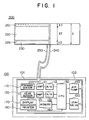
- FIG. 1 is a block diagram of an arterial distensibility measuring apparatus according to one embodiment of this invention
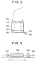
- FIG. 2 is a view of the cuff in the device of FIG. 1 put on the upper arm
- FIG. 3 is a sectional view of FIG. 2 where the artery is pressed by the cuff
- FIG. 4 is a view of the waveform of the usual aortic wave
- FIG. 5 is a view of changes of a pulse wave from the heart to the periphery
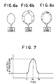
- FIGs. 6a, b and c are views of a model for explaining the principle of the arterial distensibility measuring apparatus according to this invention
- FIG. 7 is a graph of changes of injected air pressure by the air pump in the model of FIG. 6;
- FIG. 1 is a block diagram of an arterial distensibility measuring apparatus according to one embodiment of this invention
- FIG. 2 is a view of the cuff in the device of FIG. 1 put on the upper arm
- FIG. 3 is a sectional view of FIG. 2
- FIG. 8 is a graph of the measuring principle of the device of FIG. 1;
- FIGs. 9 and 10 are sectional views explaining the relationships between cuff pressures and passages of pulse waves;
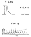
- FIGs. 11a and b are views of the output waveform of the sensor of the device of FIG. 1;
- FIG. 12 is a graph comparing the forward pulse wave and the rear wave pulse involved in the device of FIG. 1;
- FIGs. 13a, b, and c are graphs explaining the actual measuring operation of the device of FIG. 1;
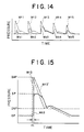
- FIGs. 14 and 15 are graphs explaning the method of recognizing an arrival at the point F in FIG. 13a.
- FIG. 1 is a block diagram showing the basic structure of the device involved in the embodment.
- This device largely comprises a device body 100 (enclosed by a one dot chain line), and a cuff 200.
- the cuff 200 has three separate bags, a forward bag 210 (indicated by a broken line, a central bag 220 (indicated by a one dot chain line) and a rear bag 230 (indicated by a two dot chain line).
- the central bag 220 and the rear bag 230 are communicated with each other by a communication passage 225.
- the central bag 220 functions as a low pass filter, and to this end it has a larger width compared with the forward and the rear bags 210, 230.
- the forward bag 210 is connected to a conduit 240 extended outside for feeding air thereinto.
- the rear bag 230 is connected to a conduit 250 extended outside for feeding air thereinto.
- This cuff is put on an upper arm in the arrangement shown in FIG. 2. With the cuff put on an upper arm as shown in FIG.
- the device 100 has the following structure.
- a tube 102 connected to the conduit 240 is connected to a forward sensor 110, and a tube 101 connected to the conduit 250 is connected to a rear sensor 120.
- the forward sensor measures the pressure of the forward bag 210
- the rear sensor measures the pressure of the rear bag 230. Both sensors are so designed that they can sufficiently detect the frequency band of the pulse waves.
- the analog signal detected by the forward sensor 110 is amplified by an amplifier 111, is converted into a digital signal, and is supplied to a CPU 130.
- the analog signal detected by the rear sensor 120 is amplified by an amplifier 121, is converted into a digital signal by an A/D converter 122 and is supplied to the CPU 130.
- the tube 102 connected to the conduit 240 is connected to an air pump 140 and a leak valve 150.
- the air pump 140 and the leak valve 150 are controlled by the CPU 130.
- the tube 101 and the tube 102 are interconnected to each other, and the central bag 220 and the rear bag 230 are interconnected to each other by the communication passage 225. Accordingly the three bags can have the same pressure.
- the volume of the central bag 220 is larger, and due to its larger volume, a pressure change of a high frequency takes place only in the forward bag 210, and it is only when a pulse wave which has been filtered by the central bag 220 impinges directly on the rear bag 230 that a pressure change takes place in the rear bag 230.
- the CPU 130 is connected to a memory 160 for storing data, a display 170 for displaying the data, and a printer 180 for outputting the data.
- the pulse waves which arrive at the cuff 200 are supplied by aortic waves.
- the basic waveform of the aortic wave is shown in FIG. 4.
- the aortic wave is plotted by taking time along the horizontal axis and taking pressure along the vertical axis.
- the aortic wave has the waveform representing a blood pressure change near the heart and the motion of the heart as it is.
- the heart dilates until the time t1 and has a diastolic pressure DP. From the time t1 to t2 the heart contracts and its pressure rises up to a systolic pressure SP.
- FIG. 5 shows the waveform changes.
- the waveforms WA to WF are obtained by measuring the pulse wave at parts distant from the position directly above the aortic valve respectively by 0 to 50 cm by a blood vessel catheter.
- the waveform WA corresponds to the aortic wave near the heart shown in FIG. 4. As seen from the showing of FIG. 5, as the pulse wave is propagated farther to the periphery, the high frequency component increases, and a maximum blood pressure TOP is increasing. This is considered to result from the fact that the blood vessels become more slender toward the perihery, and the resistance incrases.
- DNP represents a dicrotic notch pressure
- FIG. 6a shows a model, as shown in FIG. 6a, in which an air pump is connected to the mouth of an air balloon, and the air pump is so controlled that the air pressure in the balloon has a constant value a.
- the pressure injected by the air pump is controlled to be as shown in FIG. 7. That is, the air pressure is kept at a until the time t1.
- FIG. 6a shows this state retained until the time t1. From the time t1 to the time t2 the air pressure is raised from a to b, and the balloon is expanded as shown in FIG. 6b.
- the air pressure is returned to a, and at the time t3 the balloon has been shrunk to the state of FIG. 6a.
- time t2 the expansion ratio varies depending on the distensibility of the rubber of the balloon.
- the expansion ratio e1 will be considerably high as shown in FIG. 6b, but when the balloon of hard rubber of low distensibility, as shown in FIG. 6c, the expansion ratio e2 will be lower.
- the distensibility of the rubber air balloon can be indicated by the expansion ratio e.
- the expansion ratio e is a factor which depends on an injected air pressure.
- the pressure difference ⁇ P (b - a) .
- E e1 / (b - a)
- E e2 / (b - a)
- the air balloon is replaced by an artery; the air pump, by the heart; and the waveforms of FIG. 7, by a pulse wave.
- the model can be that of the circulatory organic system.
- the arteries repeat the dilation and contraction every time a pulse wave as shown in FIG. 7 arrives. Accordingly the distensibility E of the arteries can be given by dividing an expansion ratio e by a pressure difference ⁇ P.
- the apparatus according to this invention measures the distensibility of the arteries on this principle.
- FIG. 8 is a graph for explaining the basic operation.
- the actual operation a little differs from the basic operation of FIG. 8, but for the convenience of the explanation, the basic operation of FIG. 8 is first explained, and then the explanation of the actual operation will follow.
- this device has the air pump 140 and the leak valve 150, and the pressure of the respective bags 210, 220, 230 can be controlled. That is, to increase their pressure, the air pump 140 is actuated to feed air into the bags, and to decrease their pressure, the leak valve 150 is opened to let the air out of the bags.
- the cuff 200 is put on an upper arm of a person for the arterial distensibility to be measured as shown in FIG.
- the graph of FIG. 8 shows changes of the pressure in the bags immediately after the measuring operation is started. That is, after the measuring operation is started, the CPU 130 actuates the air pump 140 to feed air into the bags and gradually increase their pressure (from the point A to the point B). The respective bags 210, 220, 230 press the artery to soon completely shut the blood flow there (the point B). The relationship between the cuff 200 and the artery at this time is shown in section in FIG. 9.
- the heart is on the left side of the drawing, and the periphery is on the right side, and pulse waves are propagated from the left to the right as viewed in the drawing.
- FIG. 10a This state is shown also in FIG. 10a.
- the Swan type waveforms K in the graph of FIG. 8 indicates the amplitudes of the Korotkoff sounds generated corresponding to the respective values of gradually reduced pressure from the point D.
- the generation of the Korotkoff sounds at the pressures below the point D is due to that a part 310 of the pulse wave begins to pass the central bag 220 against the resistance thereof as shown in FIG. 10b.
- a pressure at the point D corresponds to the systolic pressure SP.
- the pulse wave passes the central bags with more ease as shown in FIG. 10c.
- the Korotkoff sound becomes loudest at the point E.
- the Korotkoff sound becomes weaker.
- the Korotkoff sound becomes very weak, and a substantially constant amplitude continues.
- the pressure corresponding to the point F is the diastolic pressure and corresponds to the state of FIG. 10d.
- the state of FIG. 10e is obtained. In this state, the bags are apart from the artery 300.
- the basic operation of this device is that in the graph of FIG. 8, the pressure is raised from the point A to the point B and then gradually lowered from the point B to the point G.
- the pressure change of the forward bag 210 is detected by the forward sensor 110 as described above, and the pressure change of the rear bag 230 is detected by the rear sensor 120.
- the pressure change of the central bag 220 is transmitted to the rear bag 230 through the conduit 225 to be detected also by the rear sensor 120. But since the central bag 220 has a larger volume, the high frequency component of the pressure change is not detected, and thus the waveform detected by the rear sensor becomes blunt (this waveform is equivalent to the aortic wave).
- the forward sensor 110 As shown in FIG. 9, A whole pulse wave from the heart impinges on the forward bag 210, which is located most upstream. Accordingly, irrespective of the shut blood flow conditions of the respective bags, the forward sensor 110 always detects the whole pulse wave as shown, e.g., in FIG. 11a. From the point B to the point F in Fig. 8, the forward sensor 110 always detects the whole pulse wave of the upper arm. From the point F to the point G, as shown in FIG. 10e, since the forward sensor 210 is apart from the artery 300, the forward bag 210 cannot detect the pulse wave in its perfect form, and the output of the forward sensor 110 gradually diminishes.
- FIG. 12 shows various waveforms detected from the point D to the point G in the graph of FIG. 8.
- the waveform depicted in the solid line in FIG. 12 is that of the rear pulse wave detected by the rear sensor 120.
- the waveform depicted in the broken line is that of the forward pulse wave detected by the forward sensor 110 (corresponding to the pulse wave WF in FIG. 5).
- the reference marks above pulse waves in FIG. 12 represent those detected at the respective points in FIG. 8.
- the pulse waves without any reference marks given above are those detected between the respective points in FIG. 8.
- the rear pulse wave depicted in the solid line will be explained.
- As the pressure is gradually decreased from the point D the amplitude of the detected rear pulse wave gradually becomes larger. As described above, when the pressure reaches the point F in FIG.
- the amplitude of the pulse wave becomes maximum and thereafter gradually diminishes. Then the forward pulse wave depicted in the broken line will be explained.
- the amplitude of the detected forward pulse wave does not change even though the pressure is gradually decreased from the point D. This is because, as described above, the pulse wave can be detected at the forward bag 210 irrespective of the shut blood flow conditions. But past the point F, the amplitude of the pulse wave continuously diminishes. This is because, as described above also, the forward bag 210 becomes apart from the artery 300.
- the pulse wave depicted by the solidline with that depicted by the broken line, it is seen that the high frequency component is cut out.
- the cuff 200 and the artery 300 have the relationship with each other as shown in FIG. 10d. That is, the inner pressure of the cuff 200 and the diastolic pressure DP are equal, so that the pulse wave can fully pass the central bag 220 to give a sufficient impact to the rear bag 230.
- the inner pressure of the cuff is higher than the diastolic pressure DP, the ordinary pulse wave cannot pass the central bag 220 as shown in FIGs. 10a to 10c, with the result that a sufficent impact is not given to the rear bag 230.
- the inner pressure of the cuff is lower than the diastolic pressure DP, as shown in FIG. 10e, the rear bag 230 leaves the artery 300, with the result that even though the ordinary pulse wave has passed the central bag 220, a sufficient impact is not given to the rear bag 230.
- the pressure values detected by the forward sensor 110 and the rear sensor 120 will be briefly explained.
- the pressure values detected in the forward bag 210 and the rear bag 230 are exactly bag inner pressures of the respective forward bag 210 and the rear bag 230, but each bag inner pressure is divided into pressures of two natures, a reference inner pressure and a change pressure.
- the reference inner pressure is that shown by the graph of FIG. 8 and is gradually diminished from the point B to the point G.
- the change pressure is a pressure change induced every time a pulse wave arrives, and has the waveform of FIG. 12.
- the pressure value detected by each sensor is a pressure value multiplexing the reference inner pressure and a change pressure. That is, the waveform of FIG. 12 is actually detected in a multiplexed form on the graph of FIG. 8.
- FIG. 10d shows the relationships between the respective bags and the artery 300 at the point F.
- the pressure change of FIG. 11a takes place. It is seen that this pressure change is an amount related with a radial expansion ratio of the vessel wall of the artery 300. If the vessel wall of the artery 300 is soft, the vessel is largely expands to much press the forward bag 210, with the result of a large pressure change.
- the air pressure b is a pressure at the moment when the artery 300 is expanded to a maximum by a pulse wave at the peak.
- the significance of the pressure value Pc at the point C will be considered with reference to FIG. 9.
- the pressure value Pc at the point C is the bag inner pressure in this critical state and can be called shut blood flow critical pressure. That is, when the pressure of the forward bag 210 reaches the shut blood flow pressure Pc, the peak pressure of the pulse wave indicated by the arrow A3 is equal to the bag inner pressure indicated by the arrow A4. In short, the shut blood flow pressure Pc is equal to a peak pressure value of the pulse wave propagated through the artery 300.
- the arterial pressure repeats the process starting with the diastolic pressure DP (pressure Pf) followed by a rise up to the shut blood flow critical pressure Pc due to the arrival of a pulse wave and returning to the diastolic pressure DP.
- ⁇ P Pc - Pf
- the determination of the crest value h of an output of the forward sensor 210 will be first explained.
- the output of the forward sensor 210 is supplied to the CPU 130 through the amplifier 111 and the A/D converter 112. If necessary, the waveform of the output can be stored by a memory 160.
- the CPU 130 easily computes the crest value h, based on the waveform. As described above, in this embodiment the crest value h at the point F in the graph of FIG. 8 is computed.
- FIG. 13b shows an enlarged view of the part L of FIG. 13a.
- the one dot chain line depicts the reference inner pressure; the broken line, the output of the forward sensor 110; and the solid line, the output of the rear sensor 120.
- the output of the rear sensor 120 depicted by the solid line will be the same number of blunt output waveforms as the output waveforms of the forward sensor 110 depicted by the broken line, in synchronization with the latter (the phase is a little shifted).
- the synchronization of five waveforms are recognized, and based on this recognition, the arrival at the point C is recognized.
- the rear sensor 120 happened to supply an output due to an arrhythmia before the pressure reaches the point C, and the reduction of the reference inner pressure can be continued.
- the shut blood flow critical pressure Pc at the point C can be given accurately.
- the determination of the diastolic pressure DP (pressure Pf) will be explained.
- the reference inner pressure is gradually decreased from the point C', and its arrival at the point F is recognized by special method.
- This recognizing method is based on a novel finding. This method will be detailed based on the basic operation of FIG. 8.
- FIG. 12 shows various pulse waves detected from the point D to the point G in FIG.
- the solid line depicts the rear pulse wave detected by the rear sensor 120, the broken line depicting the forward pulse wave detected by the forward sensor 110.
- the reference marks above pulse waves indicate the pulse waves detected at the respective points in the graph of FIG. 8.
- the pulse waves without the reference marks indicate the pulse waves detected between the respective points.
- the rear pulse wave depicted by the solid line will be noted. It has been described above that the pressure is gradually decreased from the point D, the amplitude of a detected pulse wave becomes gradually larger, and when the pressure reaches the point F, the amplitude of the pulse wave becomes maximum and thereafter gradually diminishes, while the forward pulse wave depicted by the broken line does not change its amplitude even though the pressure is gradually decreased from the point D.
- the cuff 200 and the artery 300 have the relationship with each other as shown in FIG. 10d. That is, the inner pressure of the cuff 200 and the diastolic pressure DP are equal, so that the ordinary pulse wave can pass the central bag 220 to give a sufficient impact to the rear bag 230.
- the inner pressure of the cuff is higher than the diastolic pressure DP, the ordinary pulse wave cannot pass the central bag 220 as shown in FIGs. 10a to 10c, with the result that a sufficent impact is not given to the rear bag 230.
- FIG. 12 suggests a very effective method for judging whether or not the reference inner pressure of the cuff has reached the point F, i.e., whether or not the pressure value has been decreased to the diastolic pressure DP. That is, at the point F the forward pulse wave (depicted by the broken line) and the rear pulse wave (depicted by the solid line) exactly agree with each other at the lower portions thereof. Reversely, it can be said that the reference inner pressure of the cuff and the diastolic pressure DP have agreed with each other at the point when their lower portions exactly agree with each other. This is a fact no one other than the inventor of this application has found.
- the central bag 220 functoning as a low pass filter cuts at the diastolic pressure DP the high frequency component of an intrinsic waveform of a propagated pulse wave. Accordingy it is necessary that the central bag 220 has a width large enough to function as this low pass filter, and it has been experimentally confirmed that generally a width of 9 cm or more is enough to do this function.
- the CPU 130 gradually diminishes the reference inner pressure from the point C in FIG. 8 while comparing the forward pulse wave of each pulse wave supplied by the forward sensor 110 with the rear pulse wave thereof supplied by the rear sensor 120 and judging that the reference inner pressure has reached the point F when the lower portions of both pulse waves agree with each other.
- FIG. 15 is a view explaining in good detail the operation of comparing the forward pulse wave Wf3 with the rear pulse wave Wb3.
- the rear pulse wave Wb3 is delayed from the forward pulse wave Wf3 by a delay time dt, but the forward pulse wave Wf3 is shifted to the pulse wave Wf3' to agree the rising portions of the both pulse waves with each other for comparing the lower portions of the pulse waves Wf3' and Wb3.
- the lower portion is the waveform below the dicrotic notch pressure DNP.
- the waveforms perfectly agree with each other at the portions below the dicrotic notch pressure DNP. But actually such perfect agreement is impossible, and it is preferable that their agreement with an error smaller than a set error is judged agreement.
- the CPU 130 stops the operation of the leak valve 150 for a while to retain the reference inner pressure at this level. That is, the reference inner pressure does not pass the point F instanteneously, as shown in FIG. 8, but actually as shown in FIG. 13a, the reference inner pressure is retained at the diastolic pressure DP (pressure Pf) between the points F and F'.
- the enlarged view of the portion L' of this graph is shown in FIG. 13c.
- the reference inner pressure is depicted by the one dot chain line (overlapping the solid line), the output of the forward sensor 110 is depicted by the broken line, and the output of the rear sensor 120 is depicted by the solid line.
- a pulse wave is measured over five periods between the points F and F'.
- the agreement can be confirmed with respect to five periods of a pulse wave, which can prevent errors due to accidental agreement.
- the output waveform of the forward sensor 110 depicted by the broken line is used in determining a crest value h, and the average value of the five periods of a pulse wave can be used as the crest value with resultant higher precision.
- the reference inner pressure of the cuff 200 is changed to thereby measure the arterial distensibility.
- this invention gives an arterial distensibility by putting the cuff around an upper arm, measuring the shut blood flow critical pressure and the diastolic pressure generated in the cuff, and dividing a crest value due to a pessure difference generated in the cuff by a pulse wave by a difference between the above described pressures. Accordingly as long as the arterial distensibility can be conducted on this basic principle, any device can be used.
- the lower waveform to be compared is below the dicrotic notch pressure DNP, but the lower waveform may be a different waveform. For example, the part of a waveform corresponding to a lower half of its crest value may be used.
- Comparing a lower waveform is intended to compare a part other than the high frequency component cut by the central bag. Which part to be compared is optionally selected depending on designs. It is also possible to recognize the arrival at the diastolic pressure by means of the Korotkoff sounds.
- the arterial distensibility is determined by using a cuff which can shut the blood flow at a part of the arteries to be measured to measure a shut blood flow critical pressure, a diastolic pressure and a crest value of a pressure change due to a pulse wave generated in the cuff, whereby the arterial distensibility is determined. This facilitates directly measuring the arterial distensibility.
Landscapes
- Health & Medical Sciences (AREA)
- Life Sciences & Earth Sciences (AREA)
- Vascular Medicine (AREA)
- Cardiology (AREA)
- Biomedical Technology (AREA)
- Molecular Biology (AREA)
- Physiology (AREA)
- Biophysics (AREA)
- Pathology (AREA)
- Engineering & Computer Science (AREA)
- Veterinary Medicine (AREA)
- Heart & Thoracic Surgery (AREA)
- Medical Informatics (AREA)
- Physics & Mathematics (AREA)
- Surgery (AREA)
- Animal Behavior & Ethology (AREA)
- General Health & Medical Sciences (AREA)
- Public Health (AREA)
- Ophthalmology & Optometry (AREA)
- Dentistry (AREA)
- Measuring Pulse, Heart Rate, Blood Pressure Or Blood Flow (AREA)
Claims (4)
- Vorrichtung zum Messen der Dehnbarkeit von Arterien, umfassend:- eine Manschette (200) mit einem Blutströmungs-Absperrbeutel (210) zum Absperren der Blutströmung an einem zu messenden Teil einer Arterie (300);- eine Meßeinrichtung (120, 130) zum Messen eines kritischen Drucks (Pc) einer abgesperrten Blutströmung, bei dem der Zustand der abgesperrten Blutströmung des zu messenden Teils aufgehoben wird; und- eine Meßeinrichtung (130, 140, 150) zum Messen eines diastolischen Drucks (Pf) an dem zu messenden Teil;gekennzeichnet durch- eine Druckänderungs-Detektionseinrichtung (110, 130) zum Detektieren einer Druckänderung (ΔP) des Blutströmungs-Absperrbeutels (210) auf der Grundlage einer Impulswelle, die sich durch eine Arterie an dem zu messendem Teil fortpflanzt; und durch- eine Arteriendehnbarkeits-Meßeinrichtung (130) zum Teilen eines Spitzenwerts (h) der detektierten Druckänderung (ΔP) durch eine Differenz zwischen dem kritischen Druck (Pc) der abgesperrten Blutströmung und dem diastolischen Druck (Pf) zum Bestimmen der Dehnbarkeit einer Arterie.
- Vorrichtung zum Messen der Dehnbarkeit von Arterien nach Anspruch 1,
dadurch gekennzeichnet, daß- die Manschette (200) einen Blutströmungs-Absperrbeutel als vorderen Beutel, einen zentralen Beutel (220), der ein größeres Volumen als der vordere Beutel (210) besitzt und stromab von diesem angeordnet ist, sowie einen hinteren Beutel (230) aufweist, der ein kleineres Volumen als der zentrale Beutel (220) besitzt und stromab von dem zentralen Beutel (220) angeordnet ist, wobei der zentrale und der hintere Beutel (220, 230) intern miteinander kommunizieren;- die Druckänderungs-Detektionseinrichtung einen vorderen Sensor (110) zum Detektieren einer Druckänderung, die in dem vorderen Beutel (210) als vordere Impulswelle erzeugt wird, sowie einen hinteren Sensor (120) zum Detektieren einer Druckänderung aufweist, die in dem hinteren Beutel (230) als hintere Impulswelle mit einer festgesetzten Verzögerungzeit von einer Detektionszeit der vorderen Impulswelle erzeugt wird;- eine Übereinstimmungs-Beurteilungseinrichtung (130, 160) zum Überlagern der vorderen Impulswelle auf die hintere Impulsewelle mit der Verzögerungszeit vorgesehen ist, um zu beurteilen, ob untere Wellenformen der vorderen und der hinteren Impulswellen mit einer erforderlichen Genauigkeit miteinander übereinstimmen oder nicht;- die Meßeinrichtung (130, 140, 150) zum Messen des kritischen Drucks den Innendruck der betreffenden Beutel (210, 220, 230) allmählich von einem ausreichend hohen Wert vermindert und einen Wert des Innendrucks zu einem Zeitpunkt, an dem der hintere Sensor (120) ein erstes angemessenes Ausgangssignal erzeugt, als kritischen Druck (Pc) der abgesperrten Blutströmung festhält; und daß- die Meßeinrichtung (130, 140, 150) zum Messen des diastolischen Drucks den Innendruck der betreffenden Beutel (210, 220, 230) allmählich von dem kritischen Druck (Pc) der abgesperrten Blutströmung vermindert und einen Wert des Innendrucks zu einem Zeitpunkt, an dem die Übereinstimmungs-Beurteilungseinrichtung eine Übereinstimmung beurteilt, als diastolischen Druck (Pf) festhält. - Vorrichtung zum Messen der Dehnbarkeit von Arterien nach Anspruch 2, wobei die Übereinstimmungs-Beurteilungseinrichtung (130, 160) die vordere Impulswelle und die hintere Impulswelle einander derart überlagert, daß daß der ansteigende Teil der erstgenannten und der letztgenannten miteinander übereinstimmen, sowie beurteilt, ob die Wellenformen der beiden Impulswellen unter dem Druck der dicrotischen Kerbe mit einer erforderlichen Genauigkeit miteinander übereinstimmen oder nicht.
- Vorrichtung zum Messen der Dehnbarkeit von Arterien nach Anspruch 2 oder 3, wobei die Meßeinrichtung (130, 140, 150) zum Messen des kritischen Drucks und die Meßeinrichtung zum Messen des diastolischen Drucks (130, 140, 150) derart arbeiten, daß sie die Verminderung des Innendrucks in den betreffenden Beuteln (210, 220, 230) vorübergehend stoppen, wenn der Innendruck beabsichtigte Druckwerte beider Einrichtungen erreicht hat, um zu bestätigen, daß der Innendruck deren beabsichtigte Druckwerte erreicht hat.
Priority Applications (2)
| Application Number | Priority Date | Filing Date | Title |
|---|---|---|---|
| DE1990621869 DE69021869T2 (de) | 1990-05-16 | 1990-05-16 | Gerät zur Messung der Dehnbarkeit von Arterien. |
| EP19900109281 EP0456859B1 (de) | 1990-05-16 | 1990-05-16 | Gerät zur Messung der Dehnbarkeit von Arterien |
Applications Claiming Priority (1)
| Application Number | Priority Date | Filing Date | Title |
|---|---|---|---|
| EP19900109281 EP0456859B1 (de) | 1990-05-16 | 1990-05-16 | Gerät zur Messung der Dehnbarkeit von Arterien |
Publications (2)
| Publication Number | Publication Date |
|---|---|
| EP0456859A1 EP0456859A1 (de) | 1991-11-21 |
| EP0456859B1 true EP0456859B1 (de) | 1995-08-23 |
Family
ID=8203989
Family Applications (1)
| Application Number | Title | Priority Date | Filing Date |
|---|---|---|---|
| EP19900109281 Expired - Lifetime EP0456859B1 (de) | 1990-05-16 | 1990-05-16 | Gerät zur Messung der Dehnbarkeit von Arterien |
Country Status (2)
| Country | Link |
|---|---|
| EP (1) | EP0456859B1 (de) |
| DE (1) | DE69021869T2 (de) |
Families Citing this family (3)
| Publication number | Priority date | Publication date | Assignee | Title |
|---|---|---|---|---|
| US5316005A (en) * | 1990-05-17 | 1994-05-31 | Mitsuei Tomita | Apparatus for detecting and displaying blood ciculatory information |
| JP3385262B2 (ja) * | 2000-05-29 | 2003-03-10 | 日本コーリン株式会社 | 血圧測定装置 |
| KR100766305B1 (ko) * | 2001-07-25 | 2007-10-11 | 오므론 헬스캐어 가부시키가이샤 | 혈압측정장치 |
-
1990
- 1990-05-16 DE DE1990621869 patent/DE69021869T2/de not_active Expired - Fee Related
- 1990-05-16 EP EP19900109281 patent/EP0456859B1/de not_active Expired - Lifetime
Also Published As
| Publication number | Publication date |
|---|---|
| DE69021869D1 (de) | 1995-09-28 |
| EP0456859A1 (de) | 1991-11-21 |
| DE69021869T2 (de) | 1996-05-02 |
Similar Documents
| Publication | Publication Date | Title |
|---|---|---|
| US5095912A (en) | Arterial distensibility measuring apparatus | |
| US5423324A (en) | Apparatus for detecting and displaying blood circulatory information | |
| US5301675A (en) | Apparatus for measuring blood flow velocity and blood flow volume in aortas | |
| EP0483355B1 (de) | Vorrichtung zur abnahme und zur anzeige von kreislauf-parametern | |
| US6814705B2 (en) | Arteriosclerosis-degree evaluating apparatus | |
| US4245648A (en) | Method and apparatus for measuring blood pressure and pulse rate | |
| US6843772B2 (en) | Inferior-and-superior-limb blood-pressure-index measuring apparatus | |
| TWI395572B (zh) | 血壓測定裝置以及其控制方法(一) | |
| US5651369A (en) | Apparatus for detecting and displaying blood circulatory information | |
| JPH024289B2 (de) | ||
| EP1159914A3 (de) | Blutdruckmessgerät | |
| EP0456844A1 (de) | Nichtinvasives automatisches Blutdruckmessgerät | |
| US6106478A (en) | Sphygmomanometer utilizing optically detected arterial pulsation displacement | |
| US6669646B1 (en) | Arteriosclerosis evaluating apparatus | |
| EP0456859A1 (de) | Gerät zur Messung der Dehnbarkeit von Arterien | |
| US20040039290A1 (en) | Cuff pulse wave detecting apparatus and pulse-wave-propagation-velocity-related information obtaining device | |
| EP1410757A1 (de) | Vorrichtung zur Gewinnung von Vitalparametern | |
| JPH02213324A (ja) | 血圧および脈波移動時間測定用縛帯 | |
| JP4833492B2 (ja) | 血圧測定のためのシステム | |
| KR100585848B1 (ko) | 말초혈관 혈류 측정을 이용한 비관혈적 혈압 측정 시스템 | |
| US20040171945A1 (en) | Pulse wave velocity related information obtaining apparatus | |
| JPH02305547A (ja) | 脈波検出装置およびこれに用いる縛帯 | |
| JP2551668B2 (ja) | 電子血圧計 | |
| JPH0427854B2 (de) | ||
| JPH02305546A (ja) | 脈波検出装置 |
Legal Events
| Date | Code | Title | Description |
|---|---|---|---|
| PUAI | Public reference made under article 153(3) epc to a published international application that has entered the european phase |
Free format text: ORIGINAL CODE: 0009012 |
|
| 17P | Request for examination filed |
Effective date: 19900516 |
|
| AK | Designated contracting states |
Kind code of ref document: A1 Designated state(s): DE FR GB |
|
| 17Q | First examination report despatched |
Effective date: 19940405 |
|
| GRAA | (expected) grant |
Free format text: ORIGINAL CODE: 0009210 |
|
| AK | Designated contracting states |
Kind code of ref document: B1 Designated state(s): DE FR GB |
|
| REF | Corresponds to: |
Ref document number: 69021869 Country of ref document: DE Date of ref document: 19950928 |
|
| ET | Fr: translation filed | ||
| PLBE | No opposition filed within time limit |
Free format text: ORIGINAL CODE: 0009261 |
|
| STAA | Information on the status of an ep patent application or granted ep patent |
Free format text: STATUS: NO OPPOSITION FILED WITHIN TIME LIMIT |
|
| 26N | No opposition filed | ||
| PGFP | Annual fee paid to national office [announced via postgrant information from national office to epo] |
Ref country code: GB Payment date: 20010417 Year of fee payment: 12 Ref country code: FR Payment date: 20010417 Year of fee payment: 12 |
|
| PGFP | Annual fee paid to national office [announced via postgrant information from national office to epo] |
Ref country code: DE Payment date: 20010724 Year of fee payment: 12 |
|
| REG | Reference to a national code |
Ref country code: GB Ref legal event code: IF02 |
|
| PG25 | Lapsed in a contracting state [announced via postgrant information from national office to epo] |
Ref country code: GB Free format text: LAPSE BECAUSE OF NON-PAYMENT OF DUE FEES Effective date: 20020516 |
|
| PG25 | Lapsed in a contracting state [announced via postgrant information from national office to epo] |
Ref country code: DE Free format text: LAPSE BECAUSE OF NON-PAYMENT OF DUE FEES Effective date: 20021203 |
|
| GBPC | Gb: european patent ceased through non-payment of renewal fee |
Effective date: 20020516 |
|
| PG25 | Lapsed in a contracting state [announced via postgrant information from national office to epo] |
Ref country code: FR Free format text: LAPSE BECAUSE OF NON-PAYMENT OF DUE FEES Effective date: 20030131 |
|
| REG | Reference to a national code |
Ref country code: FR Ref legal event code: ST |