EP0456877A1 - Method of removal of acid components from a gas - Google Patents
Method of removal of acid components from a gas Download PDFInfo
- Publication number
- EP0456877A1 EP0456877A1 EP19900113298 EP90113298A EP0456877A1 EP 0456877 A1 EP0456877 A1 EP 0456877A1 EP 19900113298 EP19900113298 EP 19900113298 EP 90113298 A EP90113298 A EP 90113298A EP 0456877 A1 EP0456877 A1 EP 0456877A1
- Authority
- EP
- European Patent Office
- Prior art keywords
- gas
- solvent
- absorbent
- dehydration
- pressure
- Prior art date
- Legal status (The legal status is an assumption and is not a legal conclusion. Google has not performed a legal analysis and makes no representation as to the accuracy of the status listed.)
- Granted
Links
Images
Classifications
-
- C—CHEMISTRY; METALLURGY
- C10—PETROLEUM, GAS OR COKE INDUSTRIES; TECHNICAL GASES CONTAINING CARBON MONOXIDE; FUELS; LUBRICANTS; PEAT
- C10K—PURIFYING OR MODIFYING THE CHEMICAL COMPOSITION OF COMBUSTIBLE GASES CONTAINING CARBON MONOXIDE
- C10K1/00—Purifying combustible gases containing carbon monoxide
- C10K1/08—Purifying combustible gases containing carbon monoxide by washing with liquids; Reviving the used wash liquors
- C10K1/16—Purifying combustible gases containing carbon monoxide by washing with liquids; Reviving the used wash liquors with non-aqueous liquids
-
- B—PERFORMING OPERATIONS; TRANSPORTING
- B01—PHYSICAL OR CHEMICAL PROCESSES OR APPARATUS IN GENERAL
- B01D—SEPARATION
- B01D53/00—Separation of gases or vapours; Recovering vapours of volatile solvents from gases; Chemical or biological purification of waste gases, e.g. engine exhaust gases, smoke, fumes, flue gases, aerosols
- B01D53/14—Separation of gases or vapours; Recovering vapours of volatile solvents from gases; Chemical or biological purification of waste gases, e.g. engine exhaust gases, smoke, fumes, flue gases, aerosols by absorption
- B01D53/1425—Regeneration of liquid absorbents
-
- B—PERFORMING OPERATIONS; TRANSPORTING
- B01—PHYSICAL OR CHEMICAL PROCESSES OR APPARATUS IN GENERAL
- B01D—SEPARATION
- B01D53/00—Separation of gases or vapours; Recovering vapours of volatile solvents from gases; Chemical or biological purification of waste gases, e.g. engine exhaust gases, smoke, fumes, flue gases, aerosols
- B01D53/14—Separation of gases or vapours; Recovering vapours of volatile solvents from gases; Chemical or biological purification of waste gases, e.g. engine exhaust gases, smoke, fumes, flue gases, aerosols by absorption
- B01D53/1456—Removing acid components
- B01D53/1475—Removing carbon dioxide
-
- Y—GENERAL TAGGING OF NEW TECHNOLOGICAL DEVELOPMENTS; GENERAL TAGGING OF CROSS-SECTIONAL TECHNOLOGIES SPANNING OVER SEVERAL SECTIONS OF THE IPC; TECHNICAL SUBJECTS COVERED BY FORMER USPC CROSS-REFERENCE ART COLLECTIONS [XRACs] AND DIGESTS
- Y02—TECHNOLOGIES OR APPLICATIONS FOR MITIGATION OR ADAPTATION AGAINST CLIMATE CHANGE
- Y02C—CAPTURE, STORAGE, SEQUESTRATION OR DISPOSAL OF GREENHOUSE GASES [GHG]
- Y02C20/00—Capture or disposal of greenhouse gases
- Y02C20/40—Capture or disposal of greenhouse gases of CO2
-
- Y—GENERAL TAGGING OF NEW TECHNOLOGICAL DEVELOPMENTS; GENERAL TAGGING OF CROSS-SECTIONAL TECHNOLOGIES SPANNING OVER SEVERAL SECTIONS OF THE IPC; TECHNICAL SUBJECTS COVERED BY FORMER USPC CROSS-REFERENCE ART COLLECTIONS [XRACs] AND DIGESTS
- Y02—TECHNOLOGIES OR APPLICATIONS FOR MITIGATION OR ADAPTATION AGAINST CLIMATE CHANGE
- Y02P—CLIMATE CHANGE MITIGATION TECHNOLOGIES IN THE PRODUCTION OR PROCESSING OF GOODS
- Y02P20/00—Technologies relating to chemical industry
- Y02P20/151—Reduction of greenhouse gas [GHG] emissions, e.g. CO2
Definitions
- This invention relates to a method of removal of acid components from a gas, and more particularly, a new and improved process for removal of carbon dioxide from gas mixtures.
- the boiling point of dimethyl ether of triethyleneglycol which contains 10 % of water is equal to 120°C), which will cause an accelerated degradation of the organic solvent and, consequently, an increased consumption of reagents as well as additional heat losses while cooling and condensing excessive water vapor.
- the object of this invention is the development of such a method of gas purification which would allow the consumption of power and reagents for obtaining the purified gas to be cut while assuring the stability of its composition.
- This object has been attained by the method of removal of acid components from a gas which includes their absorption with organic solvent based on ethers of polyglycols followed by the regeneration of the absorbent and dehydration of a part of the regenerated absorbent by heating, which according to the invention is characterized in the fact that the dehydration of the absorbent is carried out by the combination of stripping with a gas and heating at the temperatures which are lower than the boiling point of the absorbent approximately at atmospheric pressure by 80 to 150°C, in which a gas such as air, nitrogen, hydrogen, argon, methane or the mixture thereof is used as a stripping agent.
- the temperature shall be increased up to the level higher than 100 °C to remove moisture with no stripping, but in the conditions with stripping the dehydration takes place with success at the temperatures lower than 100°C.
- the inventors of this invention have calculated the power consumption for the dehydration process of dimethyl ether of triethyleneglycol according to the method described in USA Patent No. 2,649,166 developed by the inventors when 200 kg of water per hour is removed from the solvent (see Table 4). TABLE 4 Nos. Description of characteristics Method described in USA Patent No. 2,649,166 Invention proposed 1. Temperature of dehydration, °C 100 90 to 70 2. Power consumption, KW for vacuum 50 - for stripping - 10
- the power consumption in the invention proposed in 5 times as low as that according to the known method.
- Natural or process gas which contains carbon dioxide and steam goes through line (1) into absorption zone (2) under an elevated pressure.
- the circulation rate of the absorbent which is necessary to achieve the required degree of gas purification from carbon dioxide may be different depending on the temperature and pressure of the feed gas as well as on the temperature and water content of the solvent.
- the gas purified from carbon dioxide and leaving absorber (2) top is extracted from the unit through line (4).
- the solvent which has absorbed carbon dioxide and water from the gas to be purified is extracted from the absorber through pipeline (5) and is delivered into 1st stage expander (6) where the pressure is maintained at a level lower than that of the absorber. This pressure should preferably be equal to 0.2 to 0.4 of that in the absorber.
- the gas released in the 1st stage expander is exhausted through pipeline (7) and by compresser (8) is delivered through pipeline (9) back into absorber (2).
- the solvent from the lst stage expander is exhausted through pipeline (10) and is delivered into 2nd stage expander (11) where the pressure is maintained at a level lower than that of the 1st stage expander. This pressure should preferably be equal to 1.1 to 1.9 ata.
- the gas released in the 2nd stage expander and consisting mainly of carbon dioxide (98 to 99 vo.% of CO2) is exhausted from the unit through pipeline (12).
- the partly regenerated solvent after removal of the main quantity of carbon dioxide in the 2nd stage expander (11), goes through pipeline (13) into desorber (14) for final regeneration.
- a stripping gas e.g. air or nitrogen
- a stripping gas is delivered in the quantity which corresponds to 5 to 10 volumes of the gas per 1 volume of the incoming liquid, preferably 8 volumes of the gas per 1 volume of the incoming liquid.
- a certain part (o.1 to 2 %) of the regenerated absorbent extracted from desorber (14) bottom through pipeline (16) is delivered by pump (17) into heat exchanger (18) where a heating takes place by the heat of the solvent after dehydration and then into preheater (19) where the absorbent is heated with steam or condensate up to the temperature of dehydration i.e. 80 to 150°C which is lower than the poiling point of the absorbent used for absorption. Then the absorbent is delivered into dehydration vessel (20) where the heated absorbent is stripped by a gas.
- the function of the dehydration vessel consists in evaporation of water from the incoming regenerated solvent. Its design may be either traditional as a packed or plate-type column or as a film-type tubular vessel in which the liquid flows down as a film to meet an upward flow of the stripping gas (21).
- the dehydration is carried out at the pressure near to the atmospheric one, preferably 1.1 ata.
- the operating conditions of the dehydration vessel are determined in such a way that the quantity of moisture in the stripping gas would correspond to that of moisture removed from the system.
- the absorbent after removal of moisture from it, is extracted from dehydration vessel (20) bottom through pipeline (24) after which it enters heat exchanger (18) where it gives the most its heat to the solvent going to dehydration and then through pipeline (25) enters cooler (26) where it is cooled down to the temperature lower than 25°C.
- the cooled dehydrated solvent is mixed with the regenerated absorbent leaving desorber (14) after which the whole absorbent is delivered with pump (27) through ammonia cooler (28) and pipeline (3) into absorber (2) top.
- a gas mixture in the quantity of 200 000 Nm3 at the temperature of 10°C and pressure of 30 ata is introduced into the absorber bottom, this mixture having the composition as follows. Composition of the gas, % vol. Hydrogen - 59 Nitrogen - 20 Carbon dioxide - 18 Argon, methane, and carbon monoxide - 3 Water in the gas mixture - 0.0005 Nm3/Nm3
- Dimethyl ether of triethyleneglycol (boiling point 220°C) which contains 2.5 wt.% of water is pumped at -5°C into the absorber top where the pressure of 30 ata is maintained.
- the absorbent flowrate is 1900 m3/hour.
- the purified gas which contains 0.1 vol.% of CO2 is extracted from the absorber top.
- the saturated solvent which contains carbon dioxide is extracted at +3°C from the absorber bottom and is delivered into the lst stage expander where the pressure of 6 ata is maintained.
- the temperature of the saturated solvent drops and attains + 2°C.
- the gas released in the lst stage expander (2800 Nm3/hour) and containing the most absorbed hydrogen and nitrogen (H2 -25.0, N2 -22.0, CO2 -53.0 vol. %) is delivered to the compressor suction and returns into the absorber.
- the solvent enters then the 2nd stage expander where the pressure of 1.5 ata is maintained.
- the desorption of the main quantity of absorbed carbon dioxide takes place (the composition of the outgoing fraction, % vol., is: CO2 -98.8, H2 -0.5, N2 -0.7, the quantity us 25,000 Nm3/hour).
- the solvent On desorption, the solvent is cooled down to - 1°C and enters the desorber where the pressure of 1.2 ata is maintained.
- 13,000 Nm3 of air is delivered at the ambient temperature.
- the water content of the air is 0.0162 Nm3/Nm3.
- the air and carbon dioxide are extracted from the desorber top.
- the degassed solvent is taken from the desorber bottom.
- this air passes through a condenser where it is cooled down to 60°C.
- the dehydrated solvent (10 m3/hour) goes throgh a heat exchanger, then through a cooler where it is cooled down to 30°C, then is mixed with the main quantity of the regenerated solvent, and is pumped into an ammonia cooler where it is cooled down to - 5°C and then is delivered into the absorber top.
- Dimethyl ether of diethyleneglycol (boiling point 160°C) which contains 2 wt. % of water is pumped at - 10°C into the absorber top where the pressure of 50 ata is maintained.
- the absorbent flowrate is 1,000 m3 /hour.
- the purified gas which contains 0.15 vol. % of CO2 is extracted from the absorber top.
- the saturated solvent which contains carbon dioxide is extracted at 0°C from the absorber bottom and is delivered into the lst stage expander where the pressure of 10 ata is maintained.
- the temperature of the saturated solvent drops and attains -1°C.
- the gas released in the lst stage expander (1.600 Nm3 /hour) and containing the most of absorbed hydrogen and nitrogen (H2 - 27.0, N2 -21.2, CO2 -51.8 vol. %) is delivered to the compressor suction and returns into the absorber.
- the solvent enters then the 2nd stage expander where the pressure of 1.3 ata is maintained.
- the desorption of the main quantity of absorbed carbon dioxide takes place (the composition of the outgoing fraction, % vol., is: CO2 -98.9, H2 - 0.45, N2 -0.65, the quantity is 12,500 Nm3 /hour).
- the solvent On desorption, the solvent is cooled down to - 6°C and enters the desorber where the pressure of 1.15 ata is maintained.
- 9,000 Nm3/hour of nitrogen is delivered at the temperature of 20°C.
- the nitrogen and carbon dioxide are extracted from the desorber top.
- the degassed solvent is taken from the desorber bottom. Its part, in the quantity of 2.5 m3/hour, is delivered into a heat exchanger, then into a preheater where it is preheated up to 80°C, and further into the dehydration vessel where the pressure of 1.05 ata is maintained. While stripping the hot solution with nitrogen, the evaporation and removal of 50 kg/hour of water take place, i.e. the quantity of moisture which enters this system with the gas to be purified.
- this nitrogen passes through a condenser where it is cooled down to 55°C.
- the dehydrated solvent (2.5 m3/hour) goes through a heat exchanger, then through a cooler where it is cooled down to 30°C, then is mixed with the main quantity of the regenerated solvent, and is pumped into an ammonia cooler where it is cooled down to - 10°C and then is delivered into the absorber top.
- a mixture of dimethyl ethers of polyethyleneglycol with the number of glycol residuals in the molecule of 3 to 6 (boiling point 240°C) which contains 3 wt. % of water is pumped at 0°C into the absorber top where the pressure of 40 ata is maintained.
- the absorbent flowrate is 1,600 m3 /hour.
- the purified gas which contains 0.12 vol. % of CO2 is extracted from the absorber top.
- the saturated solvent which contains carbon dioxide is extracted at + 8°C from the absorber bottom and is delivered into the 1st stage expander where the pressure of 8 ata is maintained.
- the temperature of the saturated solvent drops and attains + 7°C.
- the gas released in the 1st stage expander (2,300 Nm3/hour) and containing the most of absorbed hydrogen and nitrogen (H2 - 31.5, N2 -24.3, CO2 -44.2 vol. %) is delivered to the compressor suction and returns into the absorber.
- the solvent enters then the 2nd stage expander where the pressure of 1.6 ata is maintained.
- the desorption of the main quantity of absorbed carbon dioxide takes place (the composition of the outgoing fraction, % vol., is: CO2 -98.7, H2-0.6, N2- 0.7, the quantity is 20,000 Nm3/hour).
- the solvent On desorption, the solvent is cooled down to + 4°C and enters the desorber where the pressure of 1.3 ata is maintained.
- this gas passes through a condenser where it is cooled down to 58°C.
- the dehydrated solvent (1.3 m3 /hour) goes through a heat exchanger, then through a cooler where it is cooled down to 28°C, then is mixed with the main quantity of the regenerated solvent, and is pumped into an ammonia cooler where it is cooled down to 0°C and then is delivered into the absorber top.
Landscapes
- Chemical & Material Sciences (AREA)
- Engineering & Computer Science (AREA)
- General Chemical & Material Sciences (AREA)
- Oil, Petroleum & Natural Gas (AREA)
- Chemical Kinetics & Catalysis (AREA)
- Analytical Chemistry (AREA)
- Combustion & Propulsion (AREA)
- Organic Chemistry (AREA)
- Gas Separation By Absorption (AREA)
- Treating Waste Gases (AREA)
- Solid-Sorbent Or Filter-Aiding Compositions (AREA)
- Degasification And Air Bubble Elimination (AREA)
Abstract
Description
- This invention relates to a method of removal of acid components from a gas, and more particularly, a new and improved process for removal of carbon dioxide from gas mixtures.
- In preparation of the gases for ammonia synthesis or of other products, it is necessary that a large quantity of carbon dioxide is removed from the initial gas mixture. In order to remove CO₂ from such gases, a physical absorption process is now very widely used which is based on utilization of ethers of polyglycols. The utilization of such solvents allows the investment and operation cost to be considerably cut compared with the known industrial processes of gas purification with ethanol amines and hot potash solutions (Spravochnik Azotchkika, 2nd issue, Moscow: Khimiya, 1986).
- It is known that when ethers of polyglycols are used as absorbents of acid components, these solvents absorb also moisture from the gases to be treated and from the air used to strip acid components from saturated absorbents. But if the solutions of ethers of polyglycols contain water, this considerably reduces their absorption capacity for carbon dioxide. According to the experimental data obtained by the inventors, the CO₂ solubility in dimethyl ether of triethyleneglycol which contains 0 to 10 wt. % of water at the standard conditions (0°C and 1 atm. or 760 mm Hg) decreases by 18 % (see Table 1). At the other conditions, the solubility decreases similarly.
- The decrease of the absorption capacity of an absorbent causes however an increase of the power consumption for its circulation as well as the deterioration of the carbon dioxide removal from the gas and the impossibility of the permanent maintenance of a constant composition of the gas purified.
Table 1 Carbon Dioxide Solubility (Nm³/m³) in Dimethyl Ether of Triethyleneglycol at Different Water Contents(0°C) CO₂ partial pressure atm. H₂O content of absorbent, % wt. 0 5 10 1 2 3 4 1 7.7 7.2 6.3 2 15.2 14.2 12.5 4 30.8 28.3 25.3 6 46.3 42.6 38.0 8 63.4 60.2 55.2 10 81.5 77.4 70.9 - The technological calculations show that for an effective industrial operation of absorbents based on ethers of polyglycols, it is necessary the water content of the absorbents to be maintained at the minimum attainable level, 2 to 2.5 wt. %. According to this requirement, it is necessary the water to be permanently extracted from the operating circulating solutions of absorbents. It is known that this purpose is now attained by the methods as follows. The most widespread method is that according to USA Patent No. 2,649,166 when a certain par of the degassed solvent extracted from the desorber bottom is delivered to the dehydration evaporator. To facilitate the water evaporation process and to minimize the possible decomposition and evaporation of the solvent, a vacuum (Pres = 60 mm Hg) shall be maintained in the evaporation column at the evaporation temperature of 100°C.
- The shortcoming of this method is considerable power consumptions to make vacuum for evaporation of water (see Table 4).
- In USA Patent No. 3,837,143 another method is described for removal of acid components from gases with esters of polyglycols where the whole circulating solvent which contains up to 10 wt. % of water is delivered for dehydration into an evaporation zone where it boils for evaporation of the water which it contains. This evaporation is realized with help of the steam generated within the system. The quantity of the vapor extracted from the stripper shall be equal to that of the water removed plus the excess quantity of water up to 50 wt. %. The water necessary according to the balance is extracted from the system, and the excess condensed returns back into the stripper. The shortcoming of this method is the necessity of heating the whole quantity of circulating absorbent up to a high temperature (e.g. the boiling point of dimethyl ether of triethyleneglycol which contains 10 % of water is equal to 120°C), which will cause an accelerated degradation of the organic solvent and, consequently, an increased consumption of reagents as well as additional heat losses while cooling and condensing excessive water vapor.
- The object of this invention is the development of such a method of gas purification which would allow the consumption of power and reagents for obtaining the purified gas to be cut while assuring the stability of its composition.
- This object has been attained by the method of removal of acid components from a gas which includes their absorption with organic solvent based on ethers of polyglycols followed by the regeneration of the absorbent and dehydration of a part of the regenerated absorbent by heating, which according to the invention is characterized in the fact that the dehydration of the absorbent is carried out by the combination of stripping with a gas and heating at the temperatures which are lower than the boiling point of the absorbent approximately at atmospheric pressure by 80 to 150°C, in which a gas such as air, nitrogen, hydrogen, argon, methane or the mixture thereof is used as a stripping agent.
-
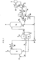
- Figure shows a block diagram of the system according to the present invention.
- The substantial advantages of the method proposed include the possibility of assuring a deep dehydration of the circulating absorbent at its minimum losses and minimum power consumptions. Thus, the inventors of this invention have obtained experimental data on the degree and rate of dehydration of dimethyl ether of triethyleneglycol and other ethers at different conditions, several of these data being given in Table 2.
TABLE 2 Time of experiment, hours Water concentration in the solvent, % wt. With no stripping With stripping with air t of dehydration (°C) 125 100 100 90 0 3.2 3.0 10 10 2 - - 3.6 3.9 4 3.16 3.0 1.0 1.9 6 3.1 - 0.31 0.58 8 - 3.01 - 0.28 - As shown by the experimental data, when the dehydration is carried out at the atomospheric pressure, the temperature shall be increased up to the level higher than 100 °C to remove moisture with no stripping, but in the conditions with stripping the dehydration takes place with success at the temperatures lower than 100°C.
- The inventors have obtained the experimental data on the degradation rate of both pure ethers of polyglycols and their mixtures at different temperatures (see Table 3). These data show that when the heating temperature increases from 90 to 130°C, the quantity of degradation products rises from 0.76 to 2.1 wt. % in 200 hours. While carrying out the dehydration at high temperatures in an industrial process, this will cause considerable losses of an expensive organic solvent.
TABLE 3 Temperature of heating, °C (during 200 h) Composition of ether of polyglycol, % wt. Non-identified impurities Main substance CH₃(OC₂H₄)₃OCH₃ X₁ X₂ Initial composition 0.05 0.62 99.3 90 0.1 0.66 99.24 130 0.48 1.62 97.9 - As an example, the inventors of this invention have calculated the power consumption for the dehydration process of dimethyl ether of triethyleneglycol according to the method described in USA Patent No. 2,649,166 developed by the inventors when 200 kg of water per hour is removed from the solvent (see Table 4).
TABLE 4 Nos. Description of characteristics Method described in USA Patent No. 2,649,166 Invention proposed 1. Temperature of dehydration, °C 100 90 to 70 2. Power consumption, KW for vacuum 50 - for stripping - 10 - As seen from the calculation given, the power consumption in the invention proposed in 5 times as low as that according to the known method.
- In conformity with the claims of this invention, the method of removal of carbon dioxide from a gas is carried out as follows (see Figure). Natural or process gas which contains carbon dioxide and steam (the latter in the quantity which corresponds to the full or partial saturation of the gas at the given pressure and temperature) goes through line (1) into absorption zone (2) under an elevated pressure. The solvent which is an ether of polyglycol or a mixture of ethers of polyglycols and contains up to 5 wt. % of water, preferably up to 2.5 wt. %, is delivered into absorber (2) top through line (3) in the quantity which is sufficient to decrease the carbon dioxide content of the gas down to the level less than 0.15 vol. %, preferably 0.1 vol. %, at the temperature which is preferably lower than 20°C.
- The circulation rate of the absorbent which is necessary to achieve the required degree of gas purification from carbon dioxide may be different depending on the temperature and pressure of the feed gas as well as on the temperature and water content of the solvent.
- The gas purified from carbon dioxide and leaving absorber (2) top is extracted from the unit through line (4). The solvent which has absorbed carbon dioxide and water from the gas to be purified is extracted from the absorber through pipeline (5) and is delivered into 1st stage expander (6) where the pressure is maintained at a level lower than that of the absorber. This pressure should preferably be equal to 0.2 to 0.4 of that in the absorber.
- The gas released in the 1st stage expander is exhausted through pipeline (7) and by compresser (8) is delivered through pipeline (9) back into absorber (2). The solvent from the lst stage expander is exhausted through pipeline (10) and is delivered into 2nd stage expander (11) where the pressure is maintained at a level lower than that of the 1st stage expander. This pressure should preferably be equal to 1.1 to 1.9 ata. The gas released in the 2nd stage expander and consisting mainly of carbon dioxide (98 to 99 vo.% of CO₂) is exhausted from the unit through pipeline (12).
- The partly regenerated solvent, after removal of the main quantity of carbon dioxide in the 2nd stage expander (11), goes through pipeline (13) into desorber (14) for final regeneration. Into desorber (14) bottom, a stripping gas (e.g. air or nitrogen) is delivered in the quantity which corresponds to 5 to 10 volumes of the gas per 1 volume of the incoming liquid, preferably 8 volumes of the gas per 1 volume of the incoming liquid.
- In desorber (14), while stripping with a gas, the final desorption of carbon dioxide from the solvent takes place, the residual CO₂ content of the regenerated solvent having not to be more than 0.5 Nm³ /m³.
- A certain part (o.1 to 2 %) of the regenerated absorbent extracted from desorber (14) bottom through pipeline (16) is delivered by pump (17) into heat exchanger (18) where a heating takes place by the heat of the solvent after dehydration and then into preheater (19) where the absorbent is heated with steam or condensate up to the temperature of dehydration i.e. 80 to 150°C which is lower than the poiling point of the absorbent used for absorption. Then the absorbent is delivered into dehydration vessel (20) where the heated absorbent is stripped by a gas.
- The function of the dehydration vessel consists in evaporation of water from the incoming regenerated solvent. Its design may be either traditional as a packed or plate-type column or as a film-type tubular vessel in which the liquid flows down as a film to meet an upward flow of the stripping gas (21). The dehydration is carried out at the pressure near to the atmospheric one, preferably 1.1 ata.
- The operating conditions of the dehydration vessel are determined in such a way that the quantity of moisture in the stripping gas would correspond to that of moisture removed from the system.
- The whole sorbent carried away with the stripping gas is condensed in partial condenser (22) so that the gas leaving the dehydration unit (23) does not practically contain solvent vapor and, consequently, there will be practically no losses of solvent from the system.
- The absorbent, after removal of moisture from it, is extracted from dehydration vessel (20) bottom through pipeline (24) after which it enters heat exchanger (18) where it gives the most its heat to the solvent going to dehydration and then through pipeline (25) enters cooler (26) where it is cooled down to the temperature lower than 25°C. The cooled dehydrated solvent is mixed with the regenerated absorbent leaving desorber (14) after which the whole absorbent is delivered with pump (27) through ammonia cooler (28) and pipeline (3) into absorber (2) top.
- A gas mixture in the quantity of 200 000 Nm³ at the temperature of 10°C and pressure of 30 ata is introduced into the absorber bottom, this mixture having the composition as follows.
Composition of the gas, % vol. Hydrogen - 59 Nitrogen - 20 Carbon dioxide - 18 Argon, methane, and carbon monoxide - 3 Water in the gas mixture - 0.0005 Nm³/Nm³ - Dimethyl ether of triethyleneglycol (boiling point 220°C) which contains 2.5 wt.% of water is pumped at -5°C into the absorber top where the pressure of 30 ata is maintained. The absorbent flowrate is 1900 m³/hour. The purified gas which contains 0.1 vol.% of CO₂ is extracted from the absorber top.
- The saturated solvent which contains carbon dioxide is extracted at +3°C from the absorber bottom and is delivered into the lst stage expander where the pressure of 6 ata is maintained. As a result of desorption of a part of dissolved gasses from the solution on decreasing the pressure, the temperature of the saturated solvent drops and attains + 2°C. The gas released in the lst stage expander (2800 Nm³/hour) and containing the most absorbed hydrogen and nitrogen (H₂ -25.0, N₂ -22.0, CO₂ -53.0 vol. %) is delivered to the compressor suction and returns into the absorber.
- The solvent enters then the 2nd stage expander where the pressure of 1.5 ata is maintained. Here the desorption of the main quantity of absorbed carbon dioxide takes place (the composition of the outgoing fraction, % vol., is: CO₂ -98.8, H₂ -0.5, N₂ -0.7, the quantity us 25,000 Nm³/hour). On desorption, the solvent is cooled down to - 1°C and enters the desorber where the pressure of 1.2 ata is maintained. Into the desorber bottom, 13,000 Nm³ of air is delivered at the ambient temperature. The water content of the air is 0.0162 Nm³/Nm³. The air and carbon dioxide are extracted from the desorber top. The degassed solvent is taken from the desorber bottom. Its part, in the quantity of 10 m³/hour, is delivered into a heat exchanger, then into a preheater where it is preheated up to 90 °C, and further into the dehydration vessel where the pressure of 1.1 ata is maintained. While stripping the hot solution with dry air, the evaporation and removal of 250kg/hour of water take place, i.e. the quantity of moisture which enters this system with the gas to be purified and with the air used for degassing.
- To condense the solvent vapor from the outgoing stripping air, this air passes through a condenser where it is cooled down to 60°C. The dehydrated solvent (10 m³/hour) goes throgh a heat exchanger, then through a cooler where it is cooled down to 30°C, then is mixed with the main quantity of the regenerated solvent, and is pumped into an ammonia cooler where it is cooled down to - 5°C and then is delivered into the absorber top.
- A gas mixture in the quantity of 100,000 Nm³/hour, at the temperature of 15 °C and pressure of 50 ata, is introduced into the absorber bottom, the composition of the mixture being as follows:
Composition of the gas, % vol. Hydrogen - 51 Nitrogen - 20 Carbon dioxide - 25 Argon, methane, and carbon monoxide - 4 Water in the gas mixture - 0.0006 Nm³/Nm³ - Dimethyl ether of diethyleneglycol (boiling point 160°C) which contains 2 wt. % of water is pumped at - 10°C into the absorber top where the pressure of 50 ata is maintained. The absorbent flowrate is 1,000 m³ /hour. The purified gas which contains 0.15 vol. % of CO₂ is extracted from the absorber top.
- The saturated solvent which contains carbon dioxide is extracted at 0°C from the absorber bottom and is delivered into the lst stage expander where the pressure of 10 ata is maintained. As a result of desorption of a part of dissolved gasses from the solution on decreasing the pressure, the temperature of the saturated solvent drops and attains -1°C. The gas released in the lst stage expander (1.600 Nm³ /hour) and containing the most of absorbed hydrogen and nitrogen (H₂ - 27.0, N₂ -21.2, CO₂ -51.8 vol. %) is delivered to the compressor suction and returns into the absorber.
- The solvent enters then the 2nd stage expander where the pressure of 1.3 ata is maintained. Here the desorption of the main quantity of absorbed carbon dioxide takes place (the composition of the outgoing fraction, % vol., is: CO₂ -98.9, H₂ - 0.45, N₂ -0.65, the quantity is 12,500 Nm³ /hour). On desorption, the solvent is cooled down to - 6°C and enters the desorber where the pressure of 1.15 ata is maintained.
- Into the desorber bottom, 9,000 Nm³/hour of nitrogen is delivered at the temperature of 20°C. The nitrogen and carbon dioxide are extracted from the desorber top. The degassed solvent is taken from the desorber bottom. Its part, in the quantity of 2.5 m³/hour, is delivered into a heat exchanger, then into a preheater where it is preheated up to 80°C, and further into the dehydration vessel where the pressure of 1.05 ata is maintained. While stripping the hot solution with nitrogen, the evaporation and removal of 50 kg/hour of water take place, i.e. the quantity of moisture which enters this system with the gas to be purified.
- To condense the solvent vapor from the outgoing stripping nitrogen, this nitrogen passes through a condenser where it is cooled down to 55°C. The dehydrated solvent (2.5 m³/hour) goes through a heat exchanger, then through a cooler where it is cooled down to 30°C, then is mixed with the main quantity of the regenerated solvent, and is pumped into an ammonia cooler where it is cooled down to - 10°C and then is delivered into the absorber top.
- A gas mixture in the quantity of 150,000 Nm³/hour, at the temperature of 15°C and pressure of 40 ata, is introduced into the absorber bottom, the composition of the mixture being as follows:
Composition of the gas, % vol. Hydrogen - 57 Nitrogen - 21 Carbon dioxide - 19 Argon, methane, and carbon monoxide - 3 Water in the gas mixture - 0.0003 Nm³/Nm³ - A mixture of dimethyl ethers of polyethyleneglycol with the number of glycol residuals in the molecule of 3 to 6 (boiling point 240°C) which contains 3 wt. % of water is pumped at 0°C into the absorber top where the pressure of 40 ata is maintained. The absorbent flowrate is 1,600 m³ /hour. The purified gas which contains 0.12 vol. % of CO₂ is extracted from the absorber top.
- The saturated solvent which contains carbon dioxide is extracted at + 8°C from the absorber bottom and is delivered into the 1st stage expander where the pressure of 8 ata is maintained. As a result of desorption of a part of dissolved gases from the solution on decreasing the pressure, the temperature of the saturated solvent drops and attains + 7°C. The gas released in the 1st stage expander (2,300 Nm³/hour) and containing the most of absorbed hydrogen and nitrogen (H₂ - 31.5, N₂ -24.3, CO₂ -44.2 vol. %) is delivered to the compressor suction and returns into the absorber.
- The solvent enters then the 2nd stage expander where the pressure of 1.6 ata is maintained. Here the desorption of the main quantity of absorbed carbon dioxide takes place (the composition of the outgoing fraction, % vol., is: CO₂ -98.7, H₂-0.6, N₂- 0.7, the quantity is 20,000 Nm³/hour). On desorption, the solvent is cooled down to + 4°C and enters the desorber where the pressure of 1.3 ata is maintained.
- Into the desorber bottom, 12,000 Nm³/hour of nitrogen is dilevered at the temperature of 20°C. The nitrogen and carbon dioxide are extracted from the desorber top. The degassed solvent is taken from the desorber bottom. Its part, in the quantity of 1.3 m³/hour, is delivered into a heat exchanger, then into a preheater where it is preheated up to 90°C, and further into the dehydration vessel where the pressure of 1.15 ata is maintained. While stripping the hot solution with the gas which contains 24 vol.% of CH₄ , 37 vol. % of H₂, 36 vol. % of N₂ , and 3 vol. % of Ar, the evaporation and removal of 40 kg/hour of water takes place, i.e. the quantity of moisture which enters this system with the gas to be purified.
- To condense the solvent vapor from the outgoing stripping gas, this gas passes through a condenser where it is cooled down to 58°C. The dehydrated solvent (1.3 m³ /hour) goes through a heat exchanger, then through a cooler where it is cooled down to 28°C, then is mixed with the main quantity of the regenerated solvent, and is pumped into an ammonia cooler where it is cooled down to 0°C and then is delivered into the absorber top.
Claims (2)
Priority Applications (1)
| Application Number | Priority Date | Filing Date | Title |
|---|---|---|---|
| AT90113298T ATE98894T1 (en) | 1990-05-14 | 1990-07-12 | METHOD OF REMOVAL OF ACIDIC COMPONENTS FROM A GAS. |
Applications Claiming Priority (2)
| Application Number | Priority Date | Filing Date | Title |
|---|---|---|---|
| JP2123754A JPH0418911A (en) | 1990-05-14 | 1990-05-14 | How to remove acidic components from gas |
| JP123754/89 | 1990-05-14 |
Publications (2)
| Publication Number | Publication Date |
|---|---|
| EP0456877A1 true EP0456877A1 (en) | 1991-11-21 |
| EP0456877B1 EP0456877B1 (en) | 1993-12-22 |
Family
ID=14868481
Family Applications (1)
| Application Number | Title | Priority Date | Filing Date |
|---|---|---|---|
| EP90113298A Expired - Lifetime EP0456877B1 (en) | 1990-05-14 | 1990-07-12 | Method of removal of acid components from a gas |
Country Status (7)
| Country | Link |
|---|---|
| US (1) | US5066314A (en) |
| EP (1) | EP0456877B1 (en) |
| JP (1) | JPH0418911A (en) |
| AT (1) | ATE98894T1 (en) |
| CA (1) | CA2022637A1 (en) |
| DE (1) | DE69005446D1 (en) |
| RU (1) | RU2028815C1 (en) |
Cited By (1)
| Publication number | Priority date | Publication date | Assignee | Title |
|---|---|---|---|---|
| EP0770420A3 (en) * | 1995-10-23 | 1997-12-17 | Union Carbide Chemicals & Plastics Technology Corporation | Composition and method for acid gas treatment |
Families Citing this family (11)
| Publication number | Priority date | Publication date | Assignee | Title |
|---|---|---|---|---|
| US5314671A (en) * | 1990-01-19 | 1994-05-24 | Elf Aquitaine Production | Process and device for removal of H2 S |
| FR2760653B1 (en) * | 1997-03-13 | 1999-04-30 | Inst Francais Du Petrole | DEACIDIFICATION PROCESS WITH PRODUCTION OF ACID GAS IN LIQUID PHASE |
| US6203599B1 (en) * | 1999-07-28 | 2001-03-20 | Union Carbide Chemicals & Plastics Technology Corporation | Process for the removal of gas contaminants from a product gas using polyethylene glycols |
| US6174348B1 (en) * | 1999-08-17 | 2001-01-16 | Praxair Technology, Inc. | Nitrogen system for regenerating chemical solvent |
| DE10136484A1 (en) * | 2001-07-27 | 2003-02-13 | Uhde Gmbh | Process for removing gas components from technical gases, e.g. natural gas, comprises scrubbing gas components from technical gases using gas scrubbing agent, and liberating scrubbing agent charged with gas components in a separate step |
| DE10229750B4 (en) * | 2002-07-03 | 2007-03-29 | Lurgi Ag | Plant unit and method for the desorption of carbon dioxide from methanol |
| NL1026537C2 (en) * | 2004-07-01 | 2006-01-03 | Tno | Membrane gas separation. |
| CA2632425A1 (en) * | 2005-12-19 | 2007-07-05 | Fluor Technologies Corporation | Integrated compressor/stripper configurations and methods |
| CA2787146C (en) | 2010-02-17 | 2016-05-17 | Fluor Technologies Corporation | Configurations and methods of high pressure acid gas removal in the production of ultra-low sulfur gas |
| WO2014066539A1 (en) | 2012-10-24 | 2014-05-01 | Fluor Technologies Corporation | Integration methods of gas processing plant and nitrogen rejection unit for high nitrogen feed gases |
| US10000713B2 (en) | 2013-12-12 | 2018-06-19 | Fluor Technologies Corporation | Configurations and methods of flexible CO2 removal |
Citations (2)
| Publication number | Priority date | Publication date | Assignee | Title |
|---|---|---|---|---|
| GB2133717A (en) * | 1983-01-19 | 1984-08-01 | Snam Progetti | Cryogenic process for the removal of acid gases from gas mixtures by means of a solvent |
| US4749555A (en) * | 1986-10-02 | 1988-06-07 | Shell Oil Company | Process for the selective removal of hydrogen sulphide and carbonyl sulfide from light hydrocarbon gases containing carbon dioxide |
Family Cites Families (14)
| Publication number | Priority date | Publication date | Assignee | Title |
|---|---|---|---|---|
| US2649166A (en) * | 1950-05-02 | 1953-08-18 | Allied Chem & Dye Corp | Absorption of carbon dioxide from gases containing the same |
| US2826266A (en) * | 1956-07-30 | 1958-03-11 | Phillips Petroleum Co | Removal of co2 from natural gas |
| US2926753A (en) * | 1958-10-06 | 1960-03-01 | Fluor Corp | Process for carbon dioxide absorption |
| US3242642A (en) * | 1962-12-11 | 1966-03-29 | Union Oil Co | Process for removing acid constituents from gaseous mixtures |
| US3255572A (en) * | 1962-12-11 | 1966-06-14 | Union Oil Co | Extraction of acidic components from gas mixtures |
| US3383838A (en) * | 1966-06-29 | 1968-05-21 | Universal Oil Prod Co | Hydrogen purification process |
| DE1494809C3 (en) * | 1966-10-25 | 1974-01-17 | Metallgesellschaft Ag, 6000 Frankfurt | Process for scrubbing carbon dioxide from low-sulfur or sulfur-free gases |
| US3594985A (en) * | 1969-06-11 | 1971-07-27 | Allied Chem | Acid gas removal from gas mixtures |
| US3664091A (en) * | 1969-06-27 | 1972-05-23 | Fish Engineering & Constructio | Process and system for removing acid gas from natural gas |
| DE2226215C3 (en) * | 1972-05-30 | 1975-09-25 | Metallgesellschaft Ag, 6000 Frankfurt | Process for the regeneration of a loaded absorbent which is obtained when acidic components are washed out of gases |
| US3837143A (en) * | 1973-08-06 | 1974-09-24 | Allied Chem | Simultaneous drying and sweetening of wellhead natural gas |
| DE2923012A1 (en) * | 1979-06-07 | 1980-12-18 | Basf Ag | METHOD FOR THE SIMULTANEOUS REMOVAL OF WATER AND SULFURIUM FROM GASES |
| US4242108A (en) * | 1979-11-07 | 1980-12-30 | Air Products And Chemicals, Inc. | Hydrogen sulfide concentrator for acid gas removal systems |
| DE3709363C1 (en) * | 1987-03-21 | 1988-08-18 | Metallgesellschaft Ag | Process for treating two loaded wash solution streams |
-
1990
- 1990-05-14 JP JP2123754A patent/JPH0418911A/en active Pending
- 1990-07-09 US US07/549,967 patent/US5066314A/en not_active Expired - Fee Related
- 1990-07-12 DE DE90113298T patent/DE69005446D1/en not_active Expired - Lifetime
- 1990-07-12 AT AT90113298T patent/ATE98894T1/en active
- 1990-07-12 EP EP90113298A patent/EP0456877B1/en not_active Expired - Lifetime
- 1990-08-03 CA CA002022637A patent/CA2022637A1/en not_active Abandoned
- 1990-11-27 RU SU904831659A patent/RU2028815C1/en active
Patent Citations (2)
| Publication number | Priority date | Publication date | Assignee | Title |
|---|---|---|---|---|
| GB2133717A (en) * | 1983-01-19 | 1984-08-01 | Snam Progetti | Cryogenic process for the removal of acid gases from gas mixtures by means of a solvent |
| US4749555A (en) * | 1986-10-02 | 1988-06-07 | Shell Oil Company | Process for the selective removal of hydrogen sulphide and carbonyl sulfide from light hydrocarbon gases containing carbon dioxide |
Cited By (2)
| Publication number | Priority date | Publication date | Assignee | Title |
|---|---|---|---|---|
| EP0770420A3 (en) * | 1995-10-23 | 1997-12-17 | Union Carbide Chemicals & Plastics Technology Corporation | Composition and method for acid gas treatment |
| US6592779B1 (en) | 1995-10-23 | 2003-07-15 | Union Carbide Chemicals & Plastics Technology Corporation | Composition and method for acid gas treatment |
Also Published As
| Publication number | Publication date |
|---|---|
| ATE98894T1 (en) | 1994-01-15 |
| US5066314A (en) | 1991-11-19 |
| DE69005446D1 (en) | 1994-02-03 |
| EP0456877B1 (en) | 1993-12-22 |
| CA2022637A1 (en) | 1991-11-15 |
| JPH0418911A (en) | 1992-01-23 |
| RU2028815C1 (en) | 1995-02-20 |
Similar Documents
| Publication | Publication Date | Title |
|---|---|---|
| US2649166A (en) | Absorption of carbon dioxide from gases containing the same | |
| US3531917A (en) | Process for a selective removal mainly of h2s and co2 by scrubbing from fuel and synthesis gases | |
| US4080424A (en) | Process for acid gas removal from gaseous mixtures | |
| US4242108A (en) | Hydrogen sulfide concentrator for acid gas removal systems | |
| US2250925A (en) | Process for the separation of acetylene from admixture with ethylene | |
| EP1206311B1 (en) | Process for removing contaminants from gas using polyethylene glycols | |
| US4182659A (en) | Method of concentrating a water-containing glycol | |
| EP0456877B1 (en) | Method of removal of acid components from a gas | |
| US4249917A (en) | Sterilization gas separation process | |
| US4384875A (en) | Process and installation for regenerating an absorbent solution containing gaseous compounds | |
| EP0460001B1 (en) | Method for removal of ammonia from a gas mixture | |
| MY101548A (en) | Cryogenic process for the removal of acid gases from gas mixtures by means of a solvent | |
| US4057403A (en) | Gas treating process | |
| WO2005035101A1 (en) | Improved solvent use and regeneration | |
| US4149857A (en) | Process for the two-stage separation of ammonia | |
| US3375639A (en) | Extraction of acidic constituents from gas mixtures with gammabutyrolactone | |
| US3266219A (en) | Removal of acid constituents from gas mixtures | |
| EP1824585B1 (en) | Process for the dehydration of gases | |
| CN115990388B (en) | Gas recovery device and recovery method | |
| DK170853B1 (en) | Process for regeneration of zeolites. | |
| JPS6138124B2 (en) | ||
| JPH0673387A (en) | Method for separating carbon monoxide from a gas mixture | |
| GB1588339A (en) | Method of reconcentrating a watercontaining glycol | |
| RU2331461C2 (en) | Improved use and solovent recovery | |
| KR920001767B1 (en) | Method for purification of ethylene oxide |
Legal Events
| Date | Code | Title | Description |
|---|---|---|---|
| PUAI | Public reference made under article 153(3) epc to a published international application that has entered the european phase |
Free format text: ORIGINAL CODE: 0009012 |
|
| AK | Designated contracting states |
Kind code of ref document: A1 Designated state(s): AT BE CH DE DK ES FR GB GR IT LI LU NL SE |
|
| RBV | Designated contracting states (corrected) |
Designated state(s): AT BE DE ES FR GB IT NL SE |
|
| 17P | Request for examination filed |
Effective date: 19920325 |
|
| 17Q | First examination report despatched |
Effective date: 19930219 |
|
| RAP3 | Party data changed (applicant data changed or rights of an application transferred) |
Owner name: STATE SCIENTIFIC RESEARCH AND DESIGNING INSTITUTE Owner name: TOHO KAGAKU KOGYO CO., LTD. |
|
| GRAA | (expected) grant |
Free format text: ORIGINAL CODE: 0009210 |
|
| AK | Designated contracting states |
Kind code of ref document: B1 Designated state(s): AT BE DE ES FR GB IT NL SE |
|
| PG25 | Lapsed in a contracting state [announced via postgrant information from national office to epo] |
Ref country code: IT Free format text: LAPSE BECAUSE OF FAILURE TO SUBMIT A TRANSLATION OF THE DESCRIPTION OR TO PAY THE FEE WITHIN THE PRE;WARNING: LAPSES OF ITALIAN PATENTS WITH EFFECTIVE DATE BEFORE 2007 MAY HAVE OCCURRED AT ANY TIME BEFORE 2007. THE CORRECT EFFECTIVE DATE MAY BE DIFFERENT FROM THE ONE RECORDED.SCRIBED TIME-LIMIT Effective date: 19931222 Ref country code: FR Effective date: 19931222 Ref country code: AT Effective date: 19931222 Ref country code: DE Effective date: 19931222 Ref country code: BE Effective date: 19931222 Ref country code: ES Free format text: THE PATENT HAS BEEN ANNULLED BY A DECISION OF A NATIONAL AUTHORITY Effective date: 19931222 Ref country code: NL Effective date: 19931222 Ref country code: SE Effective date: 19931222 |
|
| REF | Corresponds to: |
Ref document number: 98894 Country of ref document: AT Date of ref document: 19940115 Kind code of ref document: T |
|
| REF | Corresponds to: |
Ref document number: 69005446 Country of ref document: DE Date of ref document: 19940203 |
|
| EN | Fr: translation not filed | ||
| NLV1 | Nl: lapsed or annulled due to failure to fulfill the requirements of art. 29p and 29m of the patents act | ||
| PG25 | Lapsed in a contracting state [announced via postgrant information from national office to epo] |
Ref country code: GB Effective date: 19940712 |
|
| PLBE | No opposition filed within time limit |
Free format text: ORIGINAL CODE: 0009261 |
|
| STAA | Information on the status of an ep patent application or granted ep patent |
Free format text: STATUS: NO OPPOSITION FILED WITHIN TIME LIMIT |
|
| 26N | No opposition filed | ||
| GBPC | Gb: european patent ceased through non-payment of renewal fee |
Effective date: 19940712 |