EP0456911A1 - Mischtransportapparat für Bodenmörtel und dergleichen - Google Patents
Mischtransportapparat für Bodenmörtel und dergleichen Download PDFInfo
- Publication number
- EP0456911A1 EP0456911A1 EP19900201206 EP90201206A EP0456911A1 EP 0456911 A1 EP0456911 A1 EP 0456911A1 EP 19900201206 EP19900201206 EP 19900201206 EP 90201206 A EP90201206 A EP 90201206A EP 0456911 A1 EP0456911 A1 EP 0456911A1
- Authority
- EP
- European Patent Office
- Prior art keywords
- valve
- mixing tank
- valve shaft
- ring
- mixer
- Prior art date
- Legal status (The legal status is an assumption and is not a legal conclusion. Google has not performed a legal analysis and makes no representation as to the accuracy of the status listed.)
- Granted
Links
- 239000004570 mortar (masonry) Substances 0.000 title claims abstract description 8
- 239000004568 cement Substances 0.000 claims abstract description 12
- 238000007789 sealing Methods 0.000 claims abstract description 10
- 239000000203 mixture Substances 0.000 claims abstract description 7
- 230000000694 effects Effects 0.000 description 4
- 239000004576 sand Substances 0.000 description 4
- 238000010276 construction Methods 0.000 description 2
- 239000000463 material Substances 0.000 description 2
- 239000002131 composite material Substances 0.000 description 1
- 239000004519 grease Substances 0.000 description 1
- 238000009434 installation Methods 0.000 description 1
- 238000005461 lubrication Methods 0.000 description 1
- 210000002445 nipple Anatomy 0.000 description 1
Images
Classifications
-
- B—PERFORMING OPERATIONS; TRANSPORTING
- B28—WORKING CEMENT, CLAY, OR STONE
- B28C—PREPARING CLAY; PRODUCING MIXTURES CONTAINING CLAY OR CEMENTITIOUS MATERIAL, e.g. PLASTER
- B28C5/00—Apparatus or methods for producing mixtures of cement with other substances, e.g. slurries, mortars, porous or fibrous compositions
- B28C5/08—Apparatus or methods for producing mixtures of cement with other substances, e.g. slurries, mortars, porous or fibrous compositions using driven mechanical means affecting the mixing
- B28C5/0806—Details; Accessories
- B28C5/0818—Charging or discharging gates or chutes; Sealing means
-
- B—PERFORMING OPERATIONS; TRANSPORTING
- B01—PHYSICAL OR CHEMICAL PROCESSES OR APPARATUS IN GENERAL
- B01F—MIXING, e.g. DISSOLVING, EMULSIFYING OR DISPERSING
- B01F35/00—Accessories for mixers; Auxiliary operations or auxiliary devices; Parts or details of general application
- B01F35/45—Closures or doors specially adapted for mixing receptacles; Operating mechanisms therefor
- B01F35/452—Closures or doors specially adapted for mixing receptacles; Operating mechanisms therefor by moving them in the plane of the opening
- B01F35/4521—Closures or doors specially adapted for mixing receptacles; Operating mechanisms therefor by moving them in the plane of the opening by rotating them about an axis perpendicular to the plane of the opening
-
- B—PERFORMING OPERATIONS; TRANSPORTING
- B28—WORKING CEMENT, CLAY, OR STONE
- B28C—PREPARING CLAY; PRODUCING MIXTURES CONTAINING CLAY OR CEMENTITIOUS MATERIAL, e.g. PLASTER
- B28C5/00—Apparatus or methods for producing mixtures of cement with other substances, e.g. slurries, mortars, porous or fibrous compositions
- B28C5/08—Apparatus or methods for producing mixtures of cement with other substances, e.g. slurries, mortars, porous or fibrous compositions using driven mechanical means affecting the mixing
- B28C5/10—Mixing in containers not actuated to effect the mixing
- B28C5/12—Mixing in containers not actuated to effect the mixing with stirrers sweeping through the materials, e.g. with incorporated feeding or discharging means or with oscillating stirrers
- B28C5/1223—Mixing in containers not actuated to effect the mixing with stirrers sweeping through the materials, e.g. with incorporated feeding or discharging means or with oscillating stirrers discontinuously operating mixing devices, e.g. with consecutive containers
- B28C5/123—Mixing in containers not actuated to effect the mixing with stirrers sweeping through the materials, e.g. with incorporated feeding or discharging means or with oscillating stirrers discontinuously operating mixing devices, e.g. with consecutive containers with pressure or suction means for discharging
-
- B—PERFORMING OPERATIONS; TRANSPORTING
- B65—CONVEYING; PACKING; STORING; HANDLING THIN OR FILAMENTARY MATERIAL
- B65D—CONTAINERS FOR STORAGE OR TRANSPORT OF ARTICLES OR MATERIALS, e.g. BAGS, BARRELS, BOTTLES, BOXES, CANS, CARTONS, CRATES, DRUMS, JARS, TANKS, HOPPERS, FORWARDING CONTAINERS; ACCESSORIES, CLOSURES, OR FITTINGS THEREFOR; PACKAGING ELEMENTS; PACKAGES
- B65D90/00—Component parts, details or accessories for large containers
- B65D90/54—Gates or closures
- B65D90/58—Gates or closures having closure members sliding in the plane of the opening
- B65D90/582—Gates or closures having closure members sliding in the plane of the opening having a rotational motion
- B65D90/585—Gates or closures having closure members sliding in the plane of the opening having a rotational motion around an axis perpendicular to the valve port
-
- B—PERFORMING OPERATIONS; TRANSPORTING
- B65—CONVEYING; PACKING; STORING; HANDLING THIN OR FILAMENTARY MATERIAL
- B65D—CONTAINERS FOR STORAGE OR TRANSPORT OF ARTICLES OR MATERIALS, e.g. BAGS, BARRELS, BOTTLES, BOXES, CANS, CARTONS, CRATES, DRUMS, JARS, TANKS, HOPPERS, FORWARDING CONTAINERS; ACCESSORIES, CLOSURES, OR FITTINGS THEREFOR; PACKAGING ELEMENTS; PACKAGES
- B65D90/00—Component parts, details or accessories for large containers
- B65D90/54—Gates or closures
- B65D90/62—Gates or closures having closure members movable out of the plane of the opening
- B65D90/626—Gates or closures having closure members movable out of the plane of the opening having a linear motion
-
- E—FIXED CONSTRUCTIONS
- E04—BUILDING
- E04F—FINISHING WORK ON BUILDINGS, e.g. STAIRS, FLOORS
- E04F21/00—Implements for finishing work on buildings
- E04F21/02—Implements for finishing work on buildings for applying plasticised masses to surfaces, e.g. plastering walls
- E04F21/06—Implements for applying plaster, insulating material, or the like
- E04F21/08—Mechanical implements
- E04F21/12—Mechanical implements acting by gas pressure, e.g. steam pressure
-
- B—PERFORMING OPERATIONS; TRANSPORTING
- B65—CONVEYING; PACKING; STORING; HANDLING THIN OR FILAMENTARY MATERIAL
- B65D—CONTAINERS FOR STORAGE OR TRANSPORT OF ARTICLES OR MATERIALS, e.g. BAGS, BARRELS, BOTTLES, BOXES, CANS, CARTONS, CRATES, DRUMS, JARS, TANKS, HOPPERS, FORWARDING CONTAINERS; ACCESSORIES, CLOSURES, OR FITTINGS THEREFOR; PACKAGING ELEMENTS; PACKAGES
- B65D2590/00—Component parts, details or accessories for large containers
- B65D2590/54—Gates or closures
- B65D2590/66—Operating devices therefor
- B65D2590/662—Operating devices therefor allowing a particular motion, e.g. combination of rotational and linear
Definitions
- the invention relates to a mixer-transport apparatus for floor mortar and the like, comprising a mixing tank having a filling hole that can be sealed, a transport hose being connected to the mixing tank for pneumatic transportation of an earth-humid sand-cement mixture to a site where it is used.
- mixer-transport apparatuses are known from practice and are described in a brochure of Bredel Machine- en Constructiebedrijf B.V. These known mixer-transport apparatuses are designed as trailers, which can be connected to the rear of vehicles for transportation.
- the mixing tank that is part of the apparatus typically has a volume of 220 l. In some manner or other the mixing tank is filled with sand and mortar in the proper proportions, after which these components are mixed and, using a compressor forming part of the apparatus, pneumatically transported via a hose connected to the mixing tank to, for instance, a construction site where cement floors are to be constructed.
- Pneumatic transport requires high pressure, typically amounting to 7-8 atmospheres gauge pressure, and such pressure requires that the sealing of the filling hole in the mixing tank meets high standards.
- the mixing tank is provided with one connecting stub, elliptic in cross-section, with an edge pointing inward, in which a cover, also of elliptic configuration, is disposed in such a way that the cover is pressed against the inwardly pointing edge of the connecting stub owing to the pressure obtaining in the mixing tank.
- a cover also of elliptic configuration
- the present invention aims to overcome these disadvantages and to that effect is characterized in that a remote-controlled shut-off valve is arranged at the filling hole of the mixing tank for pivoting movement about a vertical axis.
- valve can be displaced in a horizontal plane, it can be moved fully out of the path of the material charged to the mixing tank when it is being filled, so that no sticky mortar mixture will form on the surface of the valve, which would prevent a proper sealing during the pneumatic transport of the material from the mixing tank. Because the valve is flat and its control mechanism is also disposed in a horizontal plane, the construction height of the mixing tank can be reduced by about 25 cm, so that placing the mixer-transport apparatus under existing sand-cement silos no longer presents any problems whatsoever.
- the vertical valve shaft is preferably arranged for vertical movement over an adjustable distance between a pivoting position, in which the valve is just clear of an O-ring mounted in an annular groove provided in the bottom surface of a ring surrounding the filling hole, and a sealing position, in which the valve is pressed against the O-ring to seal it under the pressure obtaining in the mixing tank.
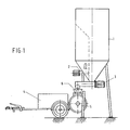
- Fig. 1 shows a known per se silo 1 comprising separate compartments for sand and cement and provided with a cement dosaging screw 2 and a sand dosaging screw 3.
- the mixing and transport apparatus 4 comprises a mixing tank 5, at the top of which a filling hole with a valve 6 is provided.
- the valve is a coned valve, as described in Dutch patent application 88.02924.
- the mixing and transport apparatus 4 has its valve 6 placed under the outlet opening of the sand dosaging screw 3 of the silo 1.
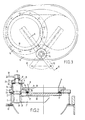
- Figs 2 and 3 show in detail the upper part of the mixing tank 5 with the valve 6.
- a connecting stub 11 is arranged, which is covered at the top by an upper plate 12.
- a circular opening 13 is provided in which a ring 14, L-shaped in cross-section, is mounted, the ring being secured to the upper plate 12 by means of bolts.
- the ring 14 comprises an inlet funnel 15 (shown in part).
- the ring 14 bounds a circular filling hole 18.
- a groove 16 is provided for accommodating an O-ring 17, which projects some distance downwards from the bottom surface of the ring 14 and engages the upper surface of a valve plate 23.
- a vertical bearing bush 19 is mounted on the upper plate 12 and welded to it.
- the bearing bush 19 accommodates the thickened guiding part 31 of a vertical valve shaft 20 whose lower end projects into stub 11.
- a bush 22 mounted onto this free end of the valve shaft 20 is a bush 22 comprising an arm 21 extending radially, onto which the horizontal valve plate 23 is mounted. In the position shown in Fig. 2 the valve plate 23, under the influence of the pressure obtaining within the mixing tank, is pressed into sealing engagement with O-ring 17.
- valve shaft 20 Provided at the top of the valve shaft 20 is a threaded part 24, onto which an adjusting nut 25 and a locking nut 26 are mounted.
- the bottom surface of the adjusting nut 25 is at a distance X from the upper edge of bearing bush 19.
- the distance or clearance X determines the distance over which the valve shaft 20, and hence also the valve plate 23, can lower in vertical direction when the pressure in the mixing tank 5 is released.
- the valve shaft 20 is then pressed down vertically by means of Belleville washers 27, arranged between the bottom edge of the bearing bush 19 and the upper edge of the bush 22 mounted on the valve shaft 20.
- a plain bearing 28 is mounted, for instance glued, on the upper edge of the bearing bush.
- a recess 29 is provided for applying a spanner for adjusting the clearance X such that when the pressure in the mixing tank is removed, the valve plate will be just clear of the O-ring 17, so that when the valve plate 23 is displaced horizontally no friction, which causes wear, will be exerted on the O-ring 17.
- a control arm 30 which, using an automatically operable air cylinder, can be pivoted into a position in which the filling hole 18 is completely sealed, or a position in which the filling hole 18 is cleared entirely, as shown in top plan view in Fig. 3.
- a grease nipple 34 is provided in the wall of the bush bearing 19, and the guiding part 31 of the valve shaft 20 at its bottom surface is sealed in axial direction by means of an O-ring 33.
Landscapes
- Engineering & Computer Science (AREA)
- Mechanical Engineering (AREA)
- Structural Engineering (AREA)
- Architecture (AREA)
- Civil Engineering (AREA)
- Chemical & Material Sciences (AREA)
- Chemical Kinetics & Catalysis (AREA)
- Accessories For Mixers (AREA)
- Preparation Of Clay, And Manufacture Of Mixtures Containing Clay Or Cement (AREA)
Priority Applications (1)
| Application Number | Priority Date | Filing Date | Title |
|---|---|---|---|
| DE1990616010 DE69016010T2 (de) | 1990-05-14 | 1990-05-14 | Mischtransportapparat für Bodenmörtel und dergleichen. |
Applications Claiming Priority (1)
| Application Number | Priority Date | Filing Date | Title |
|---|---|---|---|
| NL8802924A NL8802924A (nl) | 1988-11-28 | 1988-11-28 | Mixer-transportinrichting voor vloerspecie en dergelijke. |
Publications (2)
| Publication Number | Publication Date |
|---|---|
| EP0456911A1 true EP0456911A1 (de) | 1991-11-21 |
| EP0456911B1 EP0456911B1 (de) | 1995-01-11 |
Family
ID=19853297
Family Applications (1)
| Application Number | Title | Priority Date | Filing Date |
|---|---|---|---|
| EP90201206A Expired - Lifetime EP0456911B1 (de) | 1988-11-28 | 1990-05-14 | Mischtransportapparat für Bodenmörtel und dergleichen |
Country Status (2)
| Country | Link |
|---|---|
| EP (1) | EP0456911B1 (de) |
| NL (1) | NL8802924A (de) |
Cited By (5)
| Publication number | Priority date | Publication date | Assignee | Title |
|---|---|---|---|---|
| NL1001285C2 (nl) * | 1995-09-26 | 1997-03-28 | Lambertus Johannes Gerardus Va | Inrichting voor het mengen van ten minste twee stoffen. |
| EP1201973A1 (de) * | 2000-10-27 | 2002-05-02 | Johannes Henricus Loos | Druckbehälter mit einem Deckel |
| FR2997686A1 (fr) * | 2012-11-08 | 2014-05-09 | Pronal | Reservoir de stockage pour le stockage de liquides |
| CN104454621A (zh) * | 2014-11-04 | 2015-03-25 | 通辽矽砂工业公司 | 压差式防抽空砂浆泵 |
| CN110825001A (zh) * | 2019-11-30 | 2020-02-21 | 河南潜合自动化科技有限公司 | 一种干混砂浆控制系统 |
Families Citing this family (1)
| Publication number | Priority date | Publication date | Assignee | Title |
|---|---|---|---|---|
| CN109514732A (zh) * | 2018-11-05 | 2019-03-26 | 山东新大地环保建材有限公司 | 用于自流平砂浆的原料制备装置 |
Citations (7)
| Publication number | Priority date | Publication date | Assignee | Title |
|---|---|---|---|---|
| US1663830A (en) * | 1924-11-13 | 1928-03-27 | Eirich Ludwig | Discharging closure for mixing machines |
| FR1165381A (fr) * | 1957-01-30 | 1958-10-21 | Gondard & Cie | Trappe de vidange pour mélangeur |
| US3152624A (en) * | 1960-12-22 | 1964-10-13 | Ridley And Company Inc | Inlet valve for gun for refractories |
| DE1584521A1 (de) * | 1965-03-11 | 1970-03-19 | Rudolf Kalich | Mischbehaelter zum Mischen von Baustoffen |
| FR2178863A1 (de) * | 1972-04-01 | 1973-11-16 | Teka Baumaschinen Gmbh | |
| DE8520089U1 (de) * | 1985-07-11 | 1985-08-22 | Dr. Herfeld GmbH & Co KG, 5982 Neuenrade | Mischer |
| DE3641328A1 (de) * | 1986-12-03 | 1988-06-16 | Mann & Hummel Filter | Vorrichtung zum mischen eines koernigen oder pulverfoermigen hauptmaterials und mindestens eines zusatzstoffes |
-
1988
- 1988-11-28 NL NL8802924A patent/NL8802924A/nl not_active Application Discontinuation
-
1990
- 1990-05-14 EP EP90201206A patent/EP0456911B1/de not_active Expired - Lifetime
Patent Citations (7)
| Publication number | Priority date | Publication date | Assignee | Title |
|---|---|---|---|---|
| US1663830A (en) * | 1924-11-13 | 1928-03-27 | Eirich Ludwig | Discharging closure for mixing machines |
| FR1165381A (fr) * | 1957-01-30 | 1958-10-21 | Gondard & Cie | Trappe de vidange pour mélangeur |
| US3152624A (en) * | 1960-12-22 | 1964-10-13 | Ridley And Company Inc | Inlet valve for gun for refractories |
| DE1584521A1 (de) * | 1965-03-11 | 1970-03-19 | Rudolf Kalich | Mischbehaelter zum Mischen von Baustoffen |
| FR2178863A1 (de) * | 1972-04-01 | 1973-11-16 | Teka Baumaschinen Gmbh | |
| DE8520089U1 (de) * | 1985-07-11 | 1985-08-22 | Dr. Herfeld GmbH & Co KG, 5982 Neuenrade | Mischer |
| DE3641328A1 (de) * | 1986-12-03 | 1988-06-16 | Mann & Hummel Filter | Vorrichtung zum mischen eines koernigen oder pulverfoermigen hauptmaterials und mindestens eines zusatzstoffes |
Cited By (7)
| Publication number | Priority date | Publication date | Assignee | Title |
|---|---|---|---|---|
| NL1001285C2 (nl) * | 1995-09-26 | 1997-03-28 | Lambertus Johannes Gerardus Va | Inrichting voor het mengen van ten minste twee stoffen. |
| EP1201973A1 (de) * | 2000-10-27 | 2002-05-02 | Johannes Henricus Loos | Druckbehälter mit einem Deckel |
| BE1013815A3 (nl) * | 2000-10-27 | 2002-09-03 | Loos Johannes Henricus | Vat met deksel |
| FR2997686A1 (fr) * | 2012-11-08 | 2014-05-09 | Pronal | Reservoir de stockage pour le stockage de liquides |
| WO2014072917A1 (fr) * | 2012-11-08 | 2014-05-15 | Pronal | Réservoir de stockage pour le stockage de liquides |
| CN104454621A (zh) * | 2014-11-04 | 2015-03-25 | 通辽矽砂工业公司 | 压差式防抽空砂浆泵 |
| CN110825001A (zh) * | 2019-11-30 | 2020-02-21 | 河南潜合自动化科技有限公司 | 一种干混砂浆控制系统 |
Also Published As
| Publication number | Publication date |
|---|---|
| EP0456911B1 (de) | 1995-01-11 |
| NL8802924A (nl) | 1990-06-18 |
Similar Documents
| Publication | Publication Date | Title |
|---|---|---|
| US4379663A (en) | Vacuum sequencing system with weight controlled material draw cycle | |
| US5190132A (en) | System for loading a silo vehicle or similar with pourable bulk material | |
| US5478172A (en) | Apparatus for feeding ultrafine powder in quantitative batch operation | |
| CA1128908A (en) | Pressurized apparatus for discharging powdered reagent from a shipping container | |
| US4489862A (en) | Device for the controllable removal of bulk materials from containers | |
| US4618294A (en) | Concrete feeder apparatus | |
| EP0456911B1 (de) | Mischtransportapparat für Bodenmörtel und dergleichen | |
| US2686083A (en) | Material handling apparatus | |
| EP0678736B1 (de) | Vorrichtung zum Zumessen von pulver- oder granulatförmigem Wägegut | |
| CN101734443A (zh) | 一种分级支撑悬挂活振动防堵配料仓 | |
| US3885606A (en) | Moveable loading apparatus for fine granular and pulverized loose solids | |
| US4466760A (en) | Mobile material handler and a method for transferring bulk material | |
| US6632063B1 (en) | Method and an arrangement for filing a silo | |
| US4744701A (en) | Drum unloader | |
| US5040929A (en) | Loading system for particulate materials | |
| US3348589A (en) | Pneumatic loading apparatus | |
| US4439072A (en) | Fluidized bed discharge bin with aerating blower | |
| US5118242A (en) | Loading system | |
| US4289428A (en) | Particulate matter air assisted screw discharge apparatus | |
| US3695315A (en) | Container filler-valve volume adjustment | |
| US3592444A (en) | Mixing apparatus | |
| EP1090678A1 (de) | Einrichtung zum Dosieren von pulverförmigem oder körnigem Gut | |
| US3257151A (en) | Discharge bucket | |
| US2599235A (en) | Concrete conveying apparatus | |
| EP0403017B1 (de) | Mörteltransport-Vorrichtung |
Legal Events
| Date | Code | Title | Description |
|---|---|---|---|
| PUAI | Public reference made under article 153(3) epc to a published international application that has entered the european phase |
Free format text: ORIGINAL CODE: 0009012 |
|
| AK | Designated contracting states |
Kind code of ref document: A1 Designated state(s): DE FR NL |
|
| 17P | Request for examination filed |
Effective date: 19920520 |
|
| RAP1 | Party data changed (applicant data changed or rights of an application transferred) |
Owner name: BREMAT B.V. |
|
| RAP3 | Party data changed (applicant data changed or rights of an application transferred) |
Owner name: BREMAT B.V. |
|
| 17Q | First examination report despatched |
Effective date: 19931221 |
|
| GRAA | (expected) grant |
Free format text: ORIGINAL CODE: 0009210 |
|
| AK | Designated contracting states |
Kind code of ref document: B1 Designated state(s): DE FR NL |
|
| ET | Fr: translation filed | ||
| REF | Corresponds to: |
Ref document number: 69016010 Country of ref document: DE Date of ref document: 19950223 |
|
| PLBE | No opposition filed within time limit |
Free format text: ORIGINAL CODE: 0009261 |
|
| STAA | Information on the status of an ep patent application or granted ep patent |
Free format text: STATUS: NO OPPOSITION FILED WITHIN TIME LIMIT |
|
| 26N | No opposition filed | ||
| NLS | Nl: assignments of ep-patents |
Owner name: TECHNISCHE HANDELSONDERNEMING DE VLIEDBERG BV |
|
| REG | Reference to a national code |
Ref country code: FR Ref legal event code: TP |
|
| PGFP | Annual fee paid to national office [announced via postgrant information from national office to epo] |
Ref country code: DE Payment date: 20080513 Year of fee payment: 19 |
|
| PGFP | Annual fee paid to national office [announced via postgrant information from national office to epo] |
Ref country code: NL Payment date: 20080531 Year of fee payment: 19 |
|
| NLV4 | Nl: lapsed or anulled due to non-payment of the annual fee |
Effective date: 20091201 |
|
| PG25 | Lapsed in a contracting state [announced via postgrant information from national office to epo] |
Ref country code: NL Free format text: LAPSE BECAUSE OF NON-PAYMENT OF DUE FEES Effective date: 20091201 |
|
| REG | Reference to a national code |
Ref country code: FR Ref legal event code: ST Effective date: 20100129 |
|
| PG25 | Lapsed in a contracting state [announced via postgrant information from national office to epo] |
Ref country code: FR Free format text: LAPSE BECAUSE OF NON-PAYMENT OF DUE FEES Effective date: 20090602 |
|
| PGFP | Annual fee paid to national office [announced via postgrant information from national office to epo] |
Ref country code: FR Payment date: 20080429 Year of fee payment: 19 |
|
| PG25 | Lapsed in a contracting state [announced via postgrant information from national office to epo] |
Ref country code: DE Free format text: LAPSE BECAUSE OF NON-PAYMENT OF DUE FEES Effective date: 20091201 |