EP0456970B1 - Dispositif pour le revêtement continu d'éléments cylindriques avec un matériau élastique - Google Patents
Dispositif pour le revêtement continu d'éléments cylindriques avec un matériau élastique Download PDFInfo
- Publication number
- EP0456970B1 EP0456970B1 EP91102677A EP91102677A EP0456970B1 EP 0456970 B1 EP0456970 B1 EP 0456970B1 EP 91102677 A EP91102677 A EP 91102677A EP 91102677 A EP91102677 A EP 91102677A EP 0456970 B1 EP0456970 B1 EP 0456970B1
- Authority
- EP
- European Patent Office
- Prior art keywords
- shells
- semi
- cylindrical housing
- recited
- head
- Prior art date
- Legal status (The legal status is an assumption and is not a legal conclusion. Google has not performed a legal analysis and makes no representation as to the accuracy of the status listed.)
- Expired - Lifetime
Links
Images


Classifications
-
- B—PERFORMING OPERATIONS; TRANSPORTING
- B29—WORKING OF PLASTICS; WORKING OF SUBSTANCES IN A PLASTIC STATE IN GENERAL
- B29C—SHAPING OR JOINING OF PLASTICS; SHAPING OF MATERIAL IN A PLASTIC STATE, NOT OTHERWISE PROVIDED FOR; AFTER-TREATMENT OF THE SHAPED PRODUCTS, e.g. REPAIRING
- B29C48/00—Extrusion moulding, i.e. expressing the moulding material through a die or nozzle which imparts the desired form; Apparatus therefor
- B29C48/25—Component parts, details or accessories; Auxiliary operations
- B29C48/30—Extrusion nozzles or dies
- B29C48/32—Extrusion nozzles or dies with annular openings, e.g. for forming tubular articles
- B29C48/34—Cross-head annular extrusion nozzles, i.e. for simultaneously receiving moulding material and the preform to be coated
-
- B—PERFORMING OPERATIONS; TRANSPORTING
- B29—WORKING OF PLASTICS; WORKING OF SUBSTANCES IN A PLASTIC STATE IN GENERAL
- B29C—SHAPING OR JOINING OF PLASTICS; SHAPING OF MATERIAL IN A PLASTIC STATE, NOT OTHERWISE PROVIDED FOR; AFTER-TREATMENT OF THE SHAPED PRODUCTS, e.g. REPAIRING
- B29C48/00—Extrusion moulding, i.e. expressing the moulding material through a die or nozzle which imparts the desired form; Apparatus therefor
- B29C48/03—Extrusion moulding, i.e. expressing the moulding material through a die or nozzle which imparts the desired form; Apparatus therefor characterised by the shape of the extruded material at extrusion
- B29C48/09—Articles with cross-sections having partially or fully enclosed cavities, e.g. pipes or channels
-
- B—PERFORMING OPERATIONS; TRANSPORTING
- B29—WORKING OF PLASTICS; WORKING OF SUBSTANCES IN A PLASTIC STATE IN GENERAL
- B29C—SHAPING OR JOINING OF PLASTICS; SHAPING OF MATERIAL IN A PLASTIC STATE, NOT OTHERWISE PROVIDED FOR; AFTER-TREATMENT OF THE SHAPED PRODUCTS, e.g. REPAIRING
- B29C48/00—Extrusion moulding, i.e. expressing the moulding material through a die or nozzle which imparts the desired form; Apparatus therefor
- B29C48/25—Component parts, details or accessories; Auxiliary operations
- B29C48/256—Exchangeable extruder parts
- B29C48/2562—Mounting or handling of the die
Definitions
- the invention relates to a device of the type as described in the preamble of the first claim.
- Such a device is known from European Patent Application No. 0 231 976.
- metallic polygraphic rollers and the like covered with a rubber layer.
- the object is achieved in a device according to the preamble of the first claim by the features in the characterizing part.
- outlet-side end of the cylinder housing as a hinged half-shell for receiving the sleeve-like inner cone enables a very quick and easy change of the respective tool, but also a quick change of material.
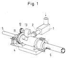
- the sheathing device shown in FIG. 1 is composed of the extruder 1, which is connected to the sheathing head 3 through the flow channel 2.
- the sheathing head 3 has a degassing opening 4 on.
- a cylindrical body 5 is guided through the head 3 and thereby covered with a rubber layer 6.
- the rubber mixture prepared in the extruder passes through the flow channel 2 into the distributor space 7, in which a sleeve-shaped material distributor 8 is arranged.
- the material distributor 8 is arranged in a bearing of the housing, not shown, and has a drive gear 11 (FIG. 1) on its gear-side end.
- a pinion 12 which is driven by a motor 13, engages in the drive gear 11.
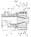
- a stationary central tube 14 is arranged coaxially in the material distributor sleeve 8, which central tube does not rotate and which is connected to the base plate by a frame-like linkage.
- an axially movable guide sleeve 26 which is held stationary during the coating process, for guiding the workpiece to be coated.
- the guide sleeve 26 is connected to a holding bracket by a linkage, not shown.
- Further guide tubes 30 to 35 are arranged in the central tube 14 for guiding the workpiece 5 to be cylindrical, in order to be able to encase workpieces of different diameters. Depending on the diameter of the workpiece 5 to be encased (FIG. 1), individual guide tubes 30-35 are removed from the head 3.
- Helical conveyor webs 17 are arranged on the back of the material distributor 8, which convey the plastic material to the outlet side of the head and distribute it uniformly over the circumference.
- a cylindrical one Housing 10 is arranged, which consists of two foldable half-shells 15 and 16 on the material outlet side of the head.
- the half-shells 15 and 16 are pivotable at their lower parting line around the bearing pin 23 and each have hinge parts 18 and 19 which engage around the bearing pin 23.
- the housing half 15 has eye bolts 20 which engage in recesses 21 for the purpose of locking the housing halves 15 and 16 and brace both housing halves against one another by means of nuts 22.
- a large ring nut 24 is provided which runs on a thread 25.
- the ring nut 24 runs circumferentially against an annular cranked stop 15a of the two housing halves 15 and 16, so that the half-shells 15 and 16 are pressed axially against the annular end face 27 and axially seal.
- An inner cone 28 is arranged in the hinged half-shells 15 and 16 and is held in the half-shells 15 and 16 by the shoulder item 36.
- the mouthpiece 29 itself is screwed to the housing halves 15 and 16 by bolts, not shown.
- a cleaning process of the head 3 is described below.
- the ring nut 24 is screwed back, for example, by a quarter turn by inserting a rod into the openings 24a and a radial rotation. This rotation causes the clamping pressure of the ring nut 24 against the stop 15a of the housing halves 15 and 16 solved.
- the inner cone 28 is freely accessible and is pulled off axially to the front, so that the rubber compound in the distributor space 7a can be pulled off from the respective guide tubes in one block.
- the cleaning of the distributor space 7a can thus be carried out very quickly, which is of crucial importance when the work is terminated or with every change of material and tools.
Landscapes
- Engineering & Computer Science (AREA)
- Mechanical Engineering (AREA)
- Manufacturing & Machinery (AREA)
- Extrusion Moulding Of Plastics Or The Like (AREA)
Claims (4)
- Appareil pour l'enrobage en continu de pièces cylindriques avec un mélange de caoutchouc ou de matière thermoplastique se composant d'une extrudeuse (1) pour la plastification du mélange et d'une tête d'enrobage (3) ainsi que d'un canal d'écoulement (2) reliant les deux machines entre elles, la tête d'enrobage (3) étant formée par un carter cylindrique (10) avec une douille distributrice de matière (8) qui tourne la-dedans et qui comprend des filets de transport (17) hélicoïdaux sur le dos et avec un tuyau central (14) stationnaire qui est arrangé coaxialement dans la douille distributrice de matière et qui sert au guidage de la pièce à enrober,
caractérisé en ce que
le carter cylindrique (10) est formé sur le côté de sortie par des semi-coupelles (15, 16) rabattables qui logent un cône intérieur (28) échangeable. - Appareil selon revendication 1,
caractérisé en ce que
les semi-coupelles (15, 16) sont conçues de sorte à permettre un verrouillage en direction radiale l'une par rapport à l'autre et en direction axiale contre le carter cylindrique (10). - Appareil selon revendication 1,
caractérisé en ce que
les semi-coupelles (15, 16) sont reliées entre elles sur un côté de leur ligne de séparation axiale au moyen d'une charnière (18, 19, 23) et qu'elles sont conçues sur l'autre côté de leur ligne de séparation axiale de façon à permettre leur fixation et leur verrouillage l'une par rapport à l'autre au moyen de boulons à oeillet pivotables (20, 22). - Appareil selon les revendications 1 et 2,
caractérisé en ce que
le dispositif de verrouillage axial des semi-coupelles (15, 16) est formé par un écrou à anneau (24) qui presse les semi-coupelles (15, 16) contre le carter de tête (9), qui se déplace sur un filet extérieur (25) du carter cylindrique (10) et qui peut être tourné contre une butée (15a) des semi-coupelles (15, 16).
Applications Claiming Priority (2)
| Application Number | Priority Date | Filing Date | Title |
|---|---|---|---|
| DE4015863A DE4015863C1 (en) | 1990-05-17 | 1990-05-17 | Appts. to continuously surround cylindrical workpieces with rubber etc - has extruder to plasticise mixt., mantle head and flow channel to connect machines |
| DE4015863 | 1990-05-17 |
Publications (3)
| Publication Number | Publication Date |
|---|---|
| EP0456970A2 EP0456970A2 (fr) | 1991-11-21 |
| EP0456970A3 EP0456970A3 (en) | 1992-03-18 |
| EP0456970B1 true EP0456970B1 (fr) | 1994-07-20 |
Family
ID=6406616
Family Applications (1)
| Application Number | Title | Priority Date | Filing Date |
|---|---|---|---|
| EP91102677A Expired - Lifetime EP0456970B1 (fr) | 1990-05-17 | 1991-02-23 | Dispositif pour le revêtement continu d'éléments cylindriques avec un matériau élastique |
Country Status (3)
| Country | Link |
|---|---|
| EP (1) | EP0456970B1 (fr) |
| JP (1) | JPH04229221A (fr) |
| DE (2) | DE4015863C1 (fr) |
Families Citing this family (5)
| Publication number | Priority date | Publication date | Assignee | Title |
|---|---|---|---|---|
| FR2687095B1 (fr) * | 1992-02-06 | 1995-06-09 | Vetrotex France Sa | Procede de fabrication d'un fil composite et produits composites obtenus a partir dudit fil. |
| FR2687094A1 (fr) * | 1992-02-06 | 1993-08-13 | Vetrotex France Sa | Dispositif de gainage d'un materiau filiforme par une matiere a l'etat fondu. |
| US5601646A (en) * | 1995-05-26 | 1997-02-11 | Alcatel Na Cable Systems, Inc. | Apparatus for applying gel to a plurality of optical fibers |
| AT3318U1 (de) * | 1998-09-29 | 2000-01-25 | Technoplast Kunststofftechnik | Vorrichtung zum extrudieren von kunststoffrohren oder profilen |
| CN111438913A (zh) * | 2020-05-26 | 2020-07-24 | 昆明智旺实业有限公司 | 一种便于改变挤出形状的熔融塑料挤出设备用出料机构 |
Family Cites Families (5)
| Publication number | Priority date | Publication date | Assignee | Title |
|---|---|---|---|---|
| US2057043A (en) * | 1934-09-29 | 1936-10-13 | Farrel Birmingham Co Inc | Attaching means for tube machine closures |
| DE1809470A1 (de) * | 1968-11-18 | 1970-06-11 | Karl Marx Stadt Maschf | Schalenverschluss,vorzugsweise zur Befestigung eines Spritzwerkzeuges an einer Schneckenpresse |
| US3833247A (en) * | 1973-03-15 | 1974-09-03 | Royle & Sons J | Breech-lock mechanism for extrusion apparatus |
| EP0095010A1 (fr) * | 1982-05-25 | 1983-11-30 | Luigi Bartoli | Tuyau isolant pour placement souterrain, procédé pour sa réalisation et machine pour la mise en oeuvre du procédé |
| DK173158B1 (da) * | 1986-01-30 | 2000-02-14 | Viradan As | Ekstruderkrydshoved til pålægning af uvulkaniseret gummimasse eller lignende på et cylindrisk emne |
-
1990
- 1990-05-17 DE DE4015863A patent/DE4015863C1/de not_active Expired - Lifetime
-
1991
- 1991-02-23 EP EP91102677A patent/EP0456970B1/fr not_active Expired - Lifetime
- 1991-02-23 DE DE59102222T patent/DE59102222D1/de not_active Expired - Fee Related
- 1991-05-16 JP JP3111942A patent/JPH04229221A/ja not_active Withdrawn
Also Published As
| Publication number | Publication date |
|---|---|
| DE4015863C1 (en) | 1991-03-07 |
| EP0456970A2 (fr) | 1991-11-21 |
| DE59102222D1 (de) | 1994-08-25 |
| JPH04229221A (ja) | 1992-08-18 |
| EP0456970A3 (en) | 1992-03-18 |
Similar Documents
| Publication | Publication Date | Title |
|---|---|---|
| DE69009320T2 (de) | Vorrichtung zum kontinuierlichen Strangpressen. | |
| EP1620246B1 (fr) | Extrudeur a arbres multiples | |
| DE2600648A1 (de) | Pelletpresse | |
| DE4305202A1 (en) | Injection moulding machine with plasticator feeding injector chamber - has side bore leading from injector chamber to nozzle to prevent any portion of shot from remaining un-injected and hence affected thermally | |
| EP0456970B1 (fr) | Dispositif pour le revêtement continu d'éléments cylindriques avec un matériau élastique | |
| DE69009859T2 (de) | Vorrichtung zur Herstellung verstärkter Polymerrohre. | |
| DE1960269A1 (de) | Maschine und Vorrichtung zum Formen von Behaeltern aus Kunststoff | |
| DE2355458B1 (de) | Vorrichtung zum Spritzgießen von Kunststoffteilchen mit glatter Oberfläche und porigem Kern | |
| EP0006489B1 (fr) | Boudineuse pour la plastification de matières plastiques | |
| DE2003282C3 (de) | Extruderkopf | |
| EP0876897A2 (fr) | Tête d'équerre pour extrudeuse | |
| EP1261472A1 (fr) | Dispositif et procede de fabrication de corps creux en plastique | |
| DE2352638A1 (de) | Vorrichtung zum reinigen von fuer die herstellung von betonrohren verwendeten giesscheiben | |
| EP0400281B1 (fr) | Dispositif pour enrober de façon continuelle des pièces à usiner cylindriques avec un matériau élastique | |
| DE822261C (de) | Spritzmaschine zum Erzeugen von gestreiften Isolierstoffmaenteln auf elektrischen Leitern oder zur Herstellung von gestreiften Schlaeuchen oder aehnlichen fortlaufenden hohlen oder vollen Gebilden | |
| DE3907866C2 (fr) | ||
| EP3392013B1 (fr) | Injecteur, partie avant d'un injecteur, procédé et installation de production de pièces moulées en plastique | |
| DE1529782B2 (de) | Spritzkopf fuer eine schneckenspritzmaschine zum plastifi zieren von kunststoff | |
| EP3153296B1 (fr) | Tête d'extrusion pour un dispositif de fabrication d'un tuyau composite | |
| EP3784464A1 (fr) | Machine de moulage par injection comprenant un arbre d'indice comportant un canal pour un fluide | |
| DE2626560A1 (de) | Handschweissgeraet | |
| DE2050563A1 (en) | Thermoplastics tube extrusion - with material passed round mandrel from above | |
| EP0583508A1 (fr) | Procédé et dispositif pour fermer, verrouiller et ouvrir automatiquement un moule divisé pour la fabrication d'articles en matière plastique | |
| AT5541U1 (de) | Rinser mit einer düseneinrichtung | |
| DE3046113A1 (de) | Kuehlvorrichtung an einer stranggiessmaschine |
Legal Events
| Date | Code | Title | Description |
|---|---|---|---|
| PUAI | Public reference made under article 153(3) epc to a published international application that has entered the european phase |
Free format text: ORIGINAL CODE: 0009012 |
|
| AK | Designated contracting states |
Kind code of ref document: A2 Designated state(s): DE DK FR GB IT NL SE |
|
| PUAL | Search report despatched |
Free format text: ORIGINAL CODE: 0009013 |
|
| AK | Designated contracting states |
Kind code of ref document: A3 Designated state(s): DE DK FR GB IT NL SE |
|
| 17P | Request for examination filed |
Effective date: 19920212 |
|
| 17Q | First examination report despatched |
Effective date: 19931126 |
|
| ITF | It: translation for a ep patent filed | ||
| GRAA | (expected) grant |
Free format text: ORIGINAL CODE: 0009210 |
|
| AK | Designated contracting states |
Kind code of ref document: B1 Designated state(s): DE DK FR GB IT NL SE |
|
| REF | Corresponds to: |
Ref document number: 59102222 Country of ref document: DE Date of ref document: 19940825 |
|
| GBT | Gb: translation of ep patent filed (gb section 77(6)(a)/1977) |
Effective date: 19940819 |
|
| ET | Fr: translation filed | ||
| EAL | Se: european patent in force in sweden |
Ref document number: 91102677.1 |
|
| PG25 | Lapsed in a contracting state [announced via postgrant information from national office to epo] |
Ref country code: GB Effective date: 19950223 Ref country code: DK Effective date: 19950223 |
|
| PG25 | Lapsed in a contracting state [announced via postgrant information from national office to epo] |
Ref country code: SE Effective date: 19950224 |
|
| PLBE | No opposition filed within time limit |
Free format text: ORIGINAL CODE: 0009261 |
|
| STAA | Information on the status of an ep patent application or granted ep patent |
Free format text: STATUS: NO OPPOSITION FILED WITHIN TIME LIMIT |
|
| 26N | No opposition filed | ||
| PG25 | Lapsed in a contracting state [announced via postgrant information from national office to epo] |
Ref country code: NL Effective date: 19950901 |
|
| GBPC | Gb: european patent ceased through non-payment of renewal fee |
Effective date: 19950223 |
|
| PG25 | Lapsed in a contracting state [announced via postgrant information from national office to epo] |
Ref country code: FR Effective date: 19951031 |
|
| NLV4 | Nl: lapsed or anulled due to non-payment of the annual fee |
Effective date: 19950901 |
|
| EUG | Se: european patent has lapsed |
Ref document number: 91102677.1 |
|
| PGFP | Annual fee paid to national office [announced via postgrant information from national office to epo] |
Ref country code: DE Payment date: 19951202 Year of fee payment: 6 |
|
| REG | Reference to a national code |
Ref country code: FR Ref legal event code: ST |
|
| PG25 | Lapsed in a contracting state [announced via postgrant information from national office to epo] |
Ref country code: DE Effective date: 19971101 |
|
| PG25 | Lapsed in a contracting state [announced via postgrant information from national office to epo] |
Ref country code: IT Free format text: LAPSE BECAUSE OF NON-PAYMENT OF DUE FEES;WARNING: LAPSES OF ITALIAN PATENTS WITH EFFECTIVE DATE BEFORE 2007 MAY HAVE OCCURRED AT ANY TIME BEFORE 2007. THE CORRECT EFFECTIVE DATE MAY BE DIFFERENT FROM THE ONE RECORDED. Effective date: 20050223 |