EP0457036A2 - Dispositif pour le stockage en position verticale d'enveloppes rigides à quatre côtés - Google Patents
Dispositif pour le stockage en position verticale d'enveloppes rigides à quatre côtés Download PDFInfo
- Publication number
- EP0457036A2 EP0457036A2 EP91105901A EP91105901A EP0457036A2 EP 0457036 A2 EP0457036 A2 EP 0457036A2 EP 91105901 A EP91105901 A EP 91105901A EP 91105901 A EP91105901 A EP 91105901A EP 0457036 A2 EP0457036 A2 EP 0457036A2
- Authority
- EP
- European Patent Office
- Prior art keywords
- bar
- slots
- strips
- grooves
- slot
- Prior art date
- Legal status (The legal status is an assumption and is not a legal conclusion. Google has not performed a legal analysis and makes no representation as to the accuracy of the status listed.)
- Granted
Links
Images

Classifications
-
- A—HUMAN NECESSITIES
- A47—FURNITURE; DOMESTIC ARTICLES OR APPLIANCES; COFFEE MILLS; SPICE MILLS; SUCTION CLEANERS IN GENERAL
- A47F—SPECIAL FURNITURE, FITTINGS, OR ACCESSORIES FOR SHOPS, STOREHOUSES, BARS, RESTAURANTS OR THE LIKE; PAYING COUNTERS
- A47F7/00—Show stands, hangers, or shelves, adapted for particular articles or materials
- A47F7/0007—Show stands, hangers, or shelves, adapted for particular articles or materials for stacked articles; Stabilising means therefor
- A47F7/0014—Show stands, hangers, or shelves, adapted for particular articles or materials for stacked articles; Stabilising means therefor for a horizontal stack of flat articles in an almost vertical position; Stabilising means therefor
-
- A—HUMAN NECESSITIES
- A47—FURNITURE; DOMESTIC ARTICLES OR APPLIANCES; COFFEE MILLS; SPICE MILLS; SUCTION CLEANERS IN GENERAL
- A47B—TABLES; DESKS; OFFICE FURNITURE; CABINETS; DRAWERS; GENERAL DETAILS OF FURNITURE
- A47B81/00—Cabinets or racks specially adapted for other particular purposes, e.g. for storing guns or skis
- A47B81/06—Furniture aspects of radio, television, gramophone, or record cabinets
- A47B81/068—Cassette cabinets or the like
-
- A—HUMAN NECESSITIES
- A47—FURNITURE; DOMESTIC ARTICLES OR APPLIANCES; COFFEE MILLS; SPICE MILLS; SUCTION CLEANERS IN GENERAL
- A47F—SPECIAL FURNITURE, FITTINGS, OR ACCESSORIES FOR SHOPS, STOREHOUSES, BARS, RESTAURANTS OR THE LIKE; PAYING COUNTERS
- A47F3/00—Show cases or show cabinets
- A47F3/14—Display trays or containers
-
- G—PHYSICS
- G11—INFORMATION STORAGE
- G11B—INFORMATION STORAGE BASED ON RELATIVE MOVEMENT BETWEEN RECORD CARRIER AND TRANSDUCER
- G11B33/00—Constructional parts, details or accessories not provided for in the other groups of this subclass
- G11B33/02—Cabinets; Cases; Stands; Disposition of apparatus therein or thereon
- G11B33/04—Cabinets; Cases; Stands; Disposition of apparatus therein or thereon modified to store record carriers
- G11B33/0405—Cabinets; Cases; Stands; Disposition of apparatus therein or thereon modified to store record carriers for storing discs
- G11B33/0433—Multiple disc containers
- G11B33/0455—Multiple disc containers for single disc boxes
Definitions
- the invention relates to a device for standing storage of square, rigid and flat casings, with the features of the preamble of claim 1.
- Such a generic storage device contains a square bowl with pairs of parallel low side walls that rise vertically above a flat floor.
- the two longer opposite side walls are provided with a large number of prismatic pins.
- the Pins are distributed equidistantly along each side wall, in such a way that with each pin on one side wall a pin is aligned on the other side wall. This creates gaps between adjacent pegs into which CD cassettes can be inserted, which then stand on the bottom of the storage device with their edge that is in use at the bottom. Since the distance between adjacent tenons is somewhat larger than the thickness of the CD cassette, the CD cassette can be swung back and forth between a position inclined forwards and a position inclined backwards. In both cases, the CD cassette has a maximum inclination of 20 o with respect to the vertical.
- the known device is limited to the storage of this type of casing by the arrangement of the pins.
- thinner casings for example the casings of floppy disks, cannot optionally be lifted in the known device. These are much thinner than the cassettes on CDs and would swing back and forth much more strongly between the pins that serve to limit the tilt.
- an excessive inclination of the casings to be kept standing is undesirable.
- the device according to the invention is characterized by the features of claim 1.
- the use of the slots to be tapered downwards ensures that even thin cases, for example of floppy disks, can only tip back and forth by the same angle as the much stronger cassettes of CD disks.
- the thicker cassettes of CD disks will remain stuck in the tapering slot, their tilt angle forwards and backwards being limited by the flank angle of the slots.
- the thin shells of floppy disks will be able to penetrate to the bottom of the slot, but will be determined in the same way with regard to the possible tilt angle by the flank angle of the slots.
- the new device can therefore be used universally for both thick and thin casings.
- each slot contains in its flanks the same number of grooves, the longitudinal axis of which is horizontal in the use position of the device. These grooves open approximately in a V-shape to, so that there is a lower, slightly inclined to the horizontal and an upper, slightly inclined to the vertical wall. In the two stable limit positions that the casing can assume in the device, the casing lies with its lower edge on the only slightly inclined lower side or wall of the groove.
- At least one further bar running parallel to the outer bars is arranged between the two bars running at a distance from one another, which bars have slots in the same way is provided like the outer strips. This ensures that even narrow sleeves are held by the device at at least two points along the edge of the sleeve.
- a very compact and stable device is obtained if the strips are arranged on the side walls of a flat square shell and the intermediate strip, if present, is provided on the bottom of the shell.
- Such an arrangement can also be inexpensively molded, for example, by injection molding.
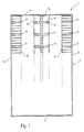
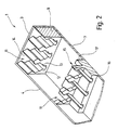
- a device 1 shown in FIGS. 1 and 2 for standing storage of square, rigid and flat sleeves, such as sleeves of CD disks, mini disks, floppy disks and the like, which are not shown. contains a flat rectangular shell 2 with pairs of parallel side walls 3, 4, 5, 6 and a substantially flat bottom 7.
- the side walls 3 ... 6 and the bottom 7 are integrally connected.
- two strips 8 and 9 are provided, which run parallel at a distance from one another and extend over the entire length of the two side walls 3 and 5 between the two side walls 4 and 6.
- the height of the two strips 8 and 9 corresponds to the height of the side walls 3 and 5.
- only the strip 9 can be seen because of the broken-off representation of the device 1.
- Both strips 8, 9 are mirror-symmetrical with respect to a plane perpendicular to the floor 7.
- Each of the two strips 8, 9 is provided with a plurality of slots 11 arranged equidistantly distributed along its longitudinal extent, in such a way that with each slot 11 in one of the two strips 8, 9 a corresponding slot 11 of the other strip 8, 9 is aligned.
- Each of the slots 8, 9 has two flanks 12, 13 which are opposite one another and converge in the direction of the base 7, and an opening 14 which points away from the base 7, ie upwards.
- each of the slots 11 is open in the direction of the opposite bar 8, 9, as can be seen in FIG. 2.
- the two flanks 12, 13 are profiled in the manner described below and have an inclination of 20 o to 30 o with respect to the vertical.
- the strip 15 is provided with two step-like widenings 16 and 17, which extend a bit extend in the direction of the opposite strips 8, 9.
- the bar 15 is also provided with equidistantly distributed slots which have the same cross-sectional profile as the slots 11 in the two side bars 8, 9, which is why the slots in the bar 15 are also designated 11, although they are in the direction of the two side bars 8, 9 are too open.
- the slots 11 in the middle bar 15 are aligned with the respectively associated slots 11 in the side bars 8, 9 and also extend a bit into the widenings 16 and 17.
- the cross-sectional profile of the slots 11 is illustrated in Figure 3.
- the cross-sectional profile is to be understood to mean the projection of the slots 11 onto a plane that runs perpendicular to an axis on which corresponding slots 11 of the strips 8, 9 and 15 are lined up.
- V-shaped grooves 18, 19 and 21 In the flank 12 are towards the bottom 7 contain a total of three V-shaped grooves 18, 19 and 21.
- the V-shaped groove 18 is delimited by straight side walls 22, 23, the groove 19 by straight side walls 24, 25 and the groove 21 by likewise straight walls 26, 27.
- adjacent grooves 18 .. 21 merge into one another with their adjacent walls 23, 25, 26.
- the flank 13 is provided in the same way with three V-shaped grooves 29, 31, 32, which in turn are also delimited by straight side walls 33 .. 38.
- a straight piece 39 Corresponding to the height offset of the first groove 29, a straight piece 39 also remains on the flank 13 at the upper end of the slot 11.
- the angle at which the flank sections 28, 39 and the walls 22.. 27 and 33.. 38 run against one another or with respect to the vertical in one exemplary embodiment is entered in FIG. 3.
- the walls 33, 35 and 37 are inclined with respect to the vertical by an angle which is equal to or slightly greater than the angle which the opposite flank section 28 makes with the vertical direction.
- the distance between the flank section 28 and the relevant side walls 33, 35, 37, measured perpendicular to the flank section 28 or its straight extension, is approximately equal to the thickness the shell cooperating with the corresponding wall 33, 35, 37.
- the corresponding relationship also applies between the flank section 39 and the walls 22, 24, 26 on the opposite flank 12. These side walls 22, 24, 26 are also slightly more inclined with respect to the vertical than the flank section 39, and their distance from the flank section 39 or its straight extension corresponds to the thickness of the shell interacting with the respective wall 22, 24, 26.
- the distances between the V-shaped grooves 18 .. 21 and 29 .. 32 obey a special relationship.
- the distance between the nose at which the wall 23 merges into the wall 24 and the opposite nose, which is approximately at the same height and at which the wall 34 collides with the wall 35, is smaller than the distance between the flank section 28 and the wall 33 , which in turn is equal to the distance between the wall 22 and the flank section 39.
- next two grooves 19 and 31 which in turn are also at approximately the same vertical height, a relationship similar to that mentioned above applies.
- the distance the nose between wall 25 and wall 26 from the nose between wall 36 and the wall 37 has, is smaller than the distance between the flank section 39 and the wall 24 or the distance between the flank section 28 and the wall 35. Accordingly, a shell that is intended to cooperate with the grooves 19 and 31 can be the grooves above 18 and 29 pass, but does not reach the area of the grooves 21 and 32.
- the cassette of a CD disk is to be stored in the device 1 described, the cassette is inserted with one edge ahead into aligned slots 11 of the strips 8, 9, 15. Due to its thickness, the cassette can only be used up to the V-shaped grooves 18, 29, because the clear distance between the free edges of the walls 23, 34 is smaller than the thickness of the cassette. It will therefore stand up with its edge on one of the two walls 23, 34. Assume the cassette is backwards, i.e. 3, inclined to the left, then the back of the cassette will rest on the flank section 28 which runs approximately parallel to the back of the cassette. The opposite edge on the narrow side stands on the wall 34, while the cassette in the slot 11 is prevented from falling over by the wall 37 of the groove 29. The front surface of the cassette lies against this wall 33.
- the inserted cassette is not quite 10 mm deep in the slots 11, it is held securely on the corresponding edge without being able to tip over backwards.
- the inclination angle of the cassette is about 30 o . From this position, the cassette can easily be folded forward, ie to the right in FIG. 3, the one sitting in the slot 11 Narrow side of the cassette on the wall 34 makes a sliding movement in the direction of the wall 23 of the other flank 12. Because of the dimensions mentioned above, the cassette cannot fall deeper into the slot 11 when folded and can, without getting caught, assume the other forward-inclined position, in which it is inclined by approximately 20 ° in accordance with the angle of the flank section 39. In this position the cassette stands on the wall 23, ie this wall essentially absorbs the vertical force of the cassette used. The tilting moment, however, is essentially absorbed by the wall 22 in connection with the flank section 39.
- the sleeve can penetrate into the slots 11 up to the V-shaped grooves 19 and 31, so that they co-operate in the tilted stable positions through the cooperation of the flank section 28 the walls 35 and 36 or in the forwardly tilted position is held by the flank section 39 and the walls 24 and 25, ie from the groove 19.
- the new device 1 it is possible to store the casings essentially upright, the casings being independent of their thickness or thickness practically always take the same angle of inclination and can therefore be mixed in one and the same device 1.
- the angle which the inserted sleeves make with respect to the vertical is somewhat larger to the rear of the amount of the folded-away state than in the folded-forward state than in the folded-forward state, so that the label can be read better.
Landscapes
- Packaging For Recording Disks (AREA)
- Packaging Of Annular Or Rod-Shaped Articles, Wearing Apparel, Cassettes, Or The Like (AREA)
- Supplying Of Containers To The Packaging Station (AREA)
- Soil Working Implements (AREA)
- Centrifugal Separators (AREA)
- Mirrors, Picture Frames, Photograph Stands, And Related Fastening Devices (AREA)
Applications Claiming Priority (2)
| Application Number | Priority Date | Filing Date | Title |
|---|---|---|---|
| DE4015314A DE4015314C2 (de) | 1990-05-12 | 1990-05-12 | Vorrichtung zum stehenden Aufbewahren von viereckigen, steifen Hüllen |
| DE4015314 | 1990-05-12 |
Publications (3)
| Publication Number | Publication Date |
|---|---|
| EP0457036A2 true EP0457036A2 (fr) | 1991-11-21 |
| EP0457036A3 EP0457036A3 (en) | 1992-09-02 |
| EP0457036B1 EP0457036B1 (fr) | 1995-12-27 |
Family
ID=6406283
Family Applications (1)
| Application Number | Title | Priority Date | Filing Date |
|---|---|---|---|
| EP91105901A Expired - Lifetime EP0457036B1 (fr) | 1990-05-12 | 1991-04-13 | Dispositif pour le stockage en position verticale d'enveloppes rigides à quatre cÔtés |
Country Status (3)
| Country | Link |
|---|---|
| EP (1) | EP0457036B1 (fr) |
| AT (1) | ATE132288T1 (fr) |
| DE (2) | DE4015314C2 (fr) |
Cited By (3)
| Publication number | Priority date | Publication date | Assignee | Title |
|---|---|---|---|---|
| EP0860831A1 (fr) * | 1997-02-24 | 1998-08-26 | SCHÜCO International KG | Dispositif pour accueillir des supports pour des données numérique à multi-angles ou pour des cases à multi-angles ou des enveloppes contenants des supports de données numériques |
| FR2792104A1 (fr) * | 1999-04-09 | 2000-10-13 | Jackson Yu | Dispositif de stockage darticles sensiblement plans et de differentes tailles. |
| US6784813B2 (en) | 2001-02-12 | 2004-08-31 | Matrics, Inc. | Method, system, and apparatus for remote data calibration of a RFID tag population |
Families Citing this family (1)
| Publication number | Priority date | Publication date | Assignee | Title |
|---|---|---|---|---|
| DE29503199U1 (de) * | 1995-02-25 | 1995-04-20 | Fuji Magnetics GmbH, 47533 Kleve | Behälter für Datenträger |
Family Cites Families (8)
| Publication number | Priority date | Publication date | Assignee | Title |
|---|---|---|---|---|
| EP0162999B1 (fr) * | 1984-05-29 | 1988-07-20 | Ernst Stadelmann Gesellschaft m.b.H. | Réceptacle pour cassettes à bande magnétique ou similaire |
| US4629067A (en) * | 1985-06-11 | 1986-12-16 | Pavlik Patrick C | Diskette holder |
| US4657146A (en) * | 1985-11-06 | 1987-04-14 | Richard Walters | Adjustable printed circuit board rack for supporting printed circuit boards in a horizontal or a vertical position |
| EP0263227A1 (fr) * | 1986-10-06 | 1988-04-13 | Ernst Stadelmann Gesellschaft m.b.H. | Récipient pour cassettes à bande magnétique ou similaire |
| NL8800712A (nl) * | 1988-03-22 | 1989-10-16 | Robertus Antonius Meuwese | Opslaginrichting voor in het bijzonder compact-discs. |
| FR2636463B1 (fr) * | 1988-09-09 | 1990-11-23 | Gefitec Sa | Support pour boites de disques compacts |
| FR2641114B1 (fr) * | 1988-12-27 | 1995-06-30 | Valin Didier | |
| DE8911892U1 (de) * | 1989-10-06 | 1989-11-30 | Forty Four Kunststofferzeugnisse GmbH, 4050 Mönchengladbach | Vorrichtung zur Aufnahme von Hüllen von Compact-Discs od.dgl. |
-
1990
- 1990-05-12 DE DE4015314A patent/DE4015314C2/de not_active Expired - Fee Related
-
1991
- 1991-04-13 AT AT91105901T patent/ATE132288T1/de not_active IP Right Cessation
- 1991-04-13 EP EP91105901A patent/EP0457036B1/fr not_active Expired - Lifetime
- 1991-04-13 DE DE59107140T patent/DE59107140D1/de not_active Expired - Fee Related
Cited By (3)
| Publication number | Priority date | Publication date | Assignee | Title |
|---|---|---|---|---|
| EP0860831A1 (fr) * | 1997-02-24 | 1998-08-26 | SCHÜCO International KG | Dispositif pour accueillir des supports pour des données numérique à multi-angles ou pour des cases à multi-angles ou des enveloppes contenants des supports de données numériques |
| FR2792104A1 (fr) * | 1999-04-09 | 2000-10-13 | Jackson Yu | Dispositif de stockage darticles sensiblement plans et de differentes tailles. |
| US6784813B2 (en) | 2001-02-12 | 2004-08-31 | Matrics, Inc. | Method, system, and apparatus for remote data calibration of a RFID tag population |
Also Published As
| Publication number | Publication date |
|---|---|
| EP0457036B1 (fr) | 1995-12-27 |
| DE4015314A1 (de) | 1991-03-28 |
| DE59107140D1 (de) | 1996-02-08 |
| ATE132288T1 (de) | 1996-01-15 |
| EP0457036A3 (en) | 1992-09-02 |
| DE4015314C2 (de) | 1994-08-04 |
Similar Documents
| Publication | Publication Date | Title |
|---|---|---|
| DE69925709T2 (de) | Schubladengleitlagerhalter und führungsblock | |
| DE69110962T2 (de) | Präsentationsvorrichtung für in einer Reihe angeordnete Gegenstände. | |
| DE3330067C2 (fr) | ||
| DE3200310C2 (de) | Gestell aus mehreren Profilstäben | |
| DE3443634A1 (de) | Neigungsverstellbarer stuetzbock | |
| DE2737973A1 (de) | Wandtragkonsole | |
| DE2633972A1 (de) | Verbindungsanordnung fuer moebel | |
| EP0457036B1 (fr) | Dispositif pour le stockage en position verticale d'enveloppes rigides à quatre cÔtés | |
| DE2312403C2 (de) | Aktenregal | |
| DE1927710A1 (de) | Verstellbares Lagergestell | |
| CH683807A5 (de) | Vorrichtung zur Aufnahme von Schallplatten-, Tonband- oder Videokassetten. | |
| DE701894C (de) | Behaelter fuer Karteien, Registraturen u. dgl. | |
| CH687050A5 (de) | Staender fuer die Aufnahme von Gegenstaenden einheitlicher Gestalt. | |
| DE2514943C2 (de) | Werkzeughalter | |
| DE4327203C2 (de) | Vorrichtung zum Archivieren von Kassetten | |
| DE3108696C2 (de) | Längsmagazin | |
| DE29501159U1 (de) | Verbindungskonstruktion | |
| DE9306650U1 (de) | Kassette zur Aufbewahrung mehrerer plattenförmiger Datenträger o.dgl. | |
| DE7721646U1 (de) | Kassette zur aufbewahrung laenglicher gegenstaende | |
| DE2834148C2 (fr) | ||
| DE19848711B4 (de) | Schrankähnliche Anordnung mit Einschüben | |
| DE2457167C3 (de) | Kartenablage | |
| DE3231207A1 (de) | Tonbandkassettenaufnahme aus kunststoff | |
| DE3433438C2 (fr) | ||
| DE69803790T2 (de) | Verbindungseinheit und system für balken |
Legal Events
| Date | Code | Title | Description |
|---|---|---|---|
| PUAI | Public reference made under article 153(3) epc to a published international application that has entered the european phase |
Free format text: ORIGINAL CODE: 0009012 |
|
| AK | Designated contracting states |
Kind code of ref document: A2 Designated state(s): AT BE CH DE DK ES FR GB GR IT LI LU NL SE |
|
| PUAL | Search report despatched |
Free format text: ORIGINAL CODE: 0009013 |
|
| AK | Designated contracting states |
Kind code of ref document: A3 Designated state(s): AT BE CH DE DK ES FR GB GR IT LI LU NL SE |
|
| 17P | Request for examination filed |
Effective date: 19930203 |
|
| 17Q | First examination report despatched |
Effective date: 19941117 |
|
| GRAA | (expected) grant |
Free format text: ORIGINAL CODE: 0009210 |
|
| AK | Designated contracting states |
Kind code of ref document: B1 Designated state(s): AT BE CH DE DK ES FR GB GR IT LI LU NL SE |
|
| PG25 | Lapsed in a contracting state [announced via postgrant information from national office to epo] |
Ref country code: IT Free format text: LAPSE BECAUSE OF FAILURE TO SUBMIT A TRANSLATION OF THE DESCRIPTION OR TO PAY THE FEE WITHIN THE PRE;WARNING: LAPSES OF ITALIAN PATENTS WITH EFFECTIVE DATE BEFORE 2007 MAY HAVE OCCURRED AT ANY TIME BEFORE 2007. THE CORRECT EFFECTIVE DATE MAY BE DIFFERENT FROM THE ONE RECORDED.SCRIBED TIME-LIMIT Effective date: 19951227 Ref country code: NL Free format text: LAPSE BECAUSE OF FAILURE TO SUBMIT A TRANSLATION OF THE DESCRIPTION OR TO PAY THE FEE WITHIN THE PRESCRIBED TIME-LIMIT Effective date: 19951227 Ref country code: BE Effective date: 19951227 Ref country code: ES Free format text: THE PATENT HAS BEEN ANNULLED BY A DECISION OF A NATIONAL AUTHORITY Effective date: 19951227 Ref country code: GR Free format text: LAPSE BECAUSE OF FAILURE TO SUBMIT A TRANSLATION OF THE DESCRIPTION OR TO PAY THE FEE WITHIN THE PRESCRIBED TIME-LIMIT Effective date: 19951227 Ref country code: DK Effective date: 19951227 |
|
| REF | Corresponds to: |
Ref document number: 132288 Country of ref document: AT Date of ref document: 19960115 Kind code of ref document: T |
|
| REF | Corresponds to: |
Ref document number: 59107140 Country of ref document: DE Date of ref document: 19960208 |
|
| PG25 | Lapsed in a contracting state [announced via postgrant information from national office to epo] |
Ref country code: SE Effective date: 19960327 |
|
| PG25 | Lapsed in a contracting state [announced via postgrant information from national office to epo] |
Ref country code: LU Free format text: LAPSE BECAUSE OF NON-PAYMENT OF DUE FEES Effective date: 19960430 |
|
| ET | Fr: translation filed | ||
| GBT | Gb: translation of ep patent filed (gb section 77(6)(a)/1977) |
Effective date: 19960404 |
|
| REG | Reference to a national code |
Ref country code: CH Ref legal event code: NV Representative=s name: KIRKER & CIE SA |
|
| NLV1 | Nl: lapsed or annulled due to failure to fulfill the requirements of art. 29p and 29m of the patents act | ||
| PLBE | No opposition filed within time limit |
Free format text: ORIGINAL CODE: 0009261 |
|
| STAA | Information on the status of an ep patent application or granted ep patent |
Free format text: STATUS: NO OPPOSITION FILED WITHIN TIME LIMIT |
|
| 26N | No opposition filed | ||
| PGFP | Annual fee paid to national office [announced via postgrant information from national office to epo] |
Ref country code: GB Payment date: 19970408 Year of fee payment: 7 |
|
| PGFP | Annual fee paid to national office [announced via postgrant information from national office to epo] |
Ref country code: AT Payment date: 19970429 Year of fee payment: 7 |
|
| PGFP | Annual fee paid to national office [announced via postgrant information from national office to epo] |
Ref country code: CH Payment date: 19970501 Year of fee payment: 7 |
|
| PG25 | Lapsed in a contracting state [announced via postgrant information from national office to epo] |
Ref country code: GB Free format text: LAPSE BECAUSE OF NON-PAYMENT OF DUE FEES Effective date: 19980413 Ref country code: AT Free format text: LAPSE BECAUSE OF NON-PAYMENT OF DUE FEES Effective date: 19980413 |
|
| PGFP | Annual fee paid to national office [announced via postgrant information from national office to epo] |
Ref country code: FR Payment date: 19980429 Year of fee payment: 8 |
|
| PG25 | Lapsed in a contracting state [announced via postgrant information from national office to epo] |
Ref country code: CH Free format text: LAPSE BECAUSE OF NON-PAYMENT OF DUE FEES Effective date: 19980430 Ref country code: LI Free format text: LAPSE BECAUSE OF NON-PAYMENT OF DUE FEES Effective date: 19980430 |
|
| GBPC | Gb: european patent ceased through non-payment of renewal fee |
Effective date: 19980413 |
|
| REG | Reference to a national code |
Ref country code: CH Ref legal event code: PL |
|
| PG25 | Lapsed in a contracting state [announced via postgrant information from national office to epo] |
Ref country code: FR Free format text: LAPSE BECAUSE OF NON-PAYMENT OF DUE FEES Effective date: 19991231 |
|
| REG | Reference to a national code |
Ref country code: FR Ref legal event code: ST |
|
| PGFP | Annual fee paid to national office [announced via postgrant information from national office to epo] |
Ref country code: DE Payment date: 20040908 Year of fee payment: 14 |
|
| PG25 | Lapsed in a contracting state [announced via postgrant information from national office to epo] |
Ref country code: DE Free format text: LAPSE BECAUSE OF NON-PAYMENT OF DUE FEES Effective date: 20051101 |