EP0457050A1 - Palier pour tête de bielle - Google Patents
Palier pour tête de bielle Download PDFInfo
- Publication number
- EP0457050A1 EP0457050A1 EP91106273A EP91106273A EP0457050A1 EP 0457050 A1 EP0457050 A1 EP 0457050A1 EP 91106273 A EP91106273 A EP 91106273A EP 91106273 A EP91106273 A EP 91106273A EP 0457050 A1 EP0457050 A1 EP 0457050A1
- Authority
- EP
- European Patent Office
- Prior art keywords
- connecting rod
- bearing
- roller
- axial
- another
- Prior art date
- Legal status (The legal status is an assumption and is not a legal conclusion. Google has not performed a legal analysis and makes no representation as to the accuracy of the status listed.)
- Granted
Links
Images

Classifications
-
- F—MECHANICAL ENGINEERING; LIGHTING; HEATING; WEAPONS; BLASTING
- F16—ENGINEERING ELEMENTS AND UNITS; GENERAL MEASURES FOR PRODUCING AND MAINTAINING EFFECTIVE FUNCTIONING OF MACHINES OR INSTALLATIONS; THERMAL INSULATION IN GENERAL
- F16C—SHAFTS; FLEXIBLE SHAFTS; ELEMENTS OR CRANKSHAFT MECHANISMS; ROTARY BODIES OTHER THAN GEARING ELEMENTS; BEARINGS
- F16C9/00—Bearings for crankshafts or connecting-rods; Attachment of connecting-rods
- F16C9/04—Connecting-rod bearings; Attachments thereof
Definitions
- the invention relates to a mounting of at least one connecting rod on at least one crank pin of a crankshaft of a reciprocating piston machine, according to the preamble of patent claim 1.
- the object of the invention is to provide a bearing of the generic type, which is friction and wear optimized and easy to manufacture with reliable axial guidance.
- At least one, but preferably all, of the contact surfaces of the connecting rod (s) be designed spherically to a small extent.
- harmful jamming with wear that may occur is counteracted, in particular in the case of two or more connecting rods mounted next to one another on their immediately adjacent contact surfaces.
- the connecting rod eyes also experience in addition to their swiveling movement a radial displacement to one another, whereby the risk of scraping wear is particularly pronounced. Due to the spherical design of the contact surfaces, this is reliably counteracted, without widening these contact surfaces and thus an overall stronger connecting rod eye being required in a weight-increasing manner.
- For the axial guidance of the connecting rods it is sufficient if partial areas of the contact surfaces are in guide contact with one another. Furthermore, the friction between the connecting rods or between connecting rods and start collars on the crank pin is reduced. It has proven to be particularly expedient if, according to claim 2, the radius of curvature of the contact surfaces increases radially outward from the bearing bore.
- the features of claim 3 have proven to be particularly advantageous.
- the smooth rolling treatment achieves an advantageous surface compaction which noticeably increases the wear resistance on the contact surfaces.
- Claims 4-7 describe a technically favorable and precise method for producing the spherical contact surfaces, in which the connecting rod with the large connecting rod eye is clamped on a machine tool and the smooth rolling treatment is carried out using a roller with a defined pressing force.
- the punch carrying the roll is preferably moved during the smooth rolling around a defined curved path, so as to produce a crowning as defined in claim 2.
- cranks 16, 18 with their large connecting rod eyes 20, 22 are pivotally mounted on a crankshaft 10 of a reciprocating piston engine or V6 internal combustion engine, which is only shown in sections, with two crank pins 12, 14 offset from one another by 30 °.
- the connecting rod eyes 20, 22 designed in a known manner in a split design have a bearing bore 24, 26 into which bearing shells 28, 30, 32, 34 are inserted.
- the crank pins 12, 14 which are formed directly onto one another merge into the immediately adjacent crank webs 36, 38.
- Each connecting rod eye 20, 22 is provided on both sides around the bearing bores 24, 26 with radial contact surfaces 40, 42 and 44, 46 for axial guidance, the contact surfaces 40, 44 with contact collars 48, 50 on the crank webs 36, 38 and the immediately adjacent contact surfaces 42, 46 interact directly.
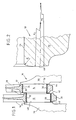
- Fig. 2 shows an enlarged section of the connecting rod eye 22 of the connecting rod 18 with the axial contact surface 46.
- this contact surface is spherical, with its radii of curvature R starting with a radius of curvature R 1 at the bearing bore 26 going radially outwards in a larger radius of curvature R2 and continuously increasing in a radius of curvature R3 constantly increasing.
- This spherical design of the contact surface 46 or all contact surfaces 40, 42, 44, 46 results in both a reduction in friction with the flat contact collars 48, 50 of the crank webs 36, 38 and, in particular, a scraping effect between the directly adjacent ones Avoid contact surfaces 42,46.
- the contact surfaces are rolled or subjected to a smooth rolling treatment.
- each connecting rod e.g. the connecting rod 16, see FIG. 3
- the connecting rod eye 20 onto the spindle 52 of a machine tool, not shown, the axis of rotation 54 of the spindle 52 with the central axis of the bearing bore 24 Connecting rod eye 20 coincides.
- the contact surface 42 is then rolled smooth, while simultaneously producing the crowning described.
- the punch 58 is pressed in the direction of the arrow 60 against the contact surface 42 while the spindle 52 is rotating, and is thereby moved along a curved path (arrows 62, 64) which is not defined in more detail.
- the cam track is specified in the machine tool in such a way that the crowning of the contact surfaces 40, 42, 44, 46 described in FIG. 2 is generated.
- the punch 58 can also be moved in the defined curved path by means of a cross slide (not shown), the peripheral surface of the roller 56 preferably being convex.
Landscapes
- Engineering & Computer Science (AREA)
- General Engineering & Computer Science (AREA)
- Mechanical Engineering (AREA)
- Shafts, Cranks, Connecting Bars, And Related Bearings (AREA)
- Rolling Contact Bearings (AREA)
- Pistons, Piston Rings, And Cylinders (AREA)
Applications Claiming Priority (2)
| Application Number | Priority Date | Filing Date | Title |
|---|---|---|---|
| DE4015536 | 1990-05-15 | ||
| DE4015536A DE4015536C1 (fr) | 1990-05-15 | 1990-05-15 |
Publications (2)
| Publication Number | Publication Date |
|---|---|
| EP0457050A1 true EP0457050A1 (fr) | 1991-11-21 |
| EP0457050B1 EP0457050B1 (fr) | 1994-03-09 |
Family
ID=6406425
Family Applications (1)
| Application Number | Title | Priority Date | Filing Date |
|---|---|---|---|
| EP91106273A Expired - Lifetime EP0457050B1 (fr) | 1990-05-15 | 1991-04-19 | Palier pour tête de bielle |
Country Status (3)
| Country | Link |
|---|---|
| EP (1) | EP0457050B1 (fr) |
| DE (2) | DE4015536C1 (fr) |
| ES (1) | ES2050008T3 (fr) |
Cited By (1)
| Publication number | Priority date | Publication date | Assignee | Title |
|---|---|---|---|---|
| DE102007045543A1 (de) * | 2007-09-24 | 2008-11-20 | Audi Ag | Brennkraftmaschine, Pleuel sowie Verfahren zur Herstellung eines Pleuels |
Families Citing this family (2)
| Publication number | Priority date | Publication date | Assignee | Title |
|---|---|---|---|---|
| DE10001993A1 (de) * | 2000-01-19 | 2001-07-26 | Volkswagen Ag | Pleuellagerung |
| DE102006017923B4 (de) * | 2006-04-18 | 2017-09-28 | Audi Ag | Verfahren zur Pleuelmontage, Pleuel sowie Kurbelwelle mit Pleuel |
Citations (3)
| Publication number | Priority date | Publication date | Assignee | Title |
|---|---|---|---|---|
| US3144786A (en) * | 1962-03-21 | 1964-08-18 | Robert A Dale | Anti-friction type mounting means for connecting rods |
| DE2238384A1 (de) * | 1972-08-04 | 1974-02-14 | Porsche Ag | Pleuel fuer brennkraftmaschinen |
| US4239303A (en) * | 1978-12-04 | 1980-12-16 | Allis-Chalmers Corporation | Full contact crankshaft bearing |
Family Cites Families (5)
| Publication number | Priority date | Publication date | Assignee | Title |
|---|---|---|---|---|
| DE524765C (de) * | 1931-05-15 | Otto Foeppl | Verfahren zur Fertigbearbeitung von Bauteilen | |
| FR477445A (fr) * | 1914-06-16 | 1915-10-20 | Moteurs Edelweiss | Bielle pour moteurs |
| DE521405C (de) * | 1928-07-10 | 1931-03-20 | Otto Foeppl | Verfahren zur Fertigbearbeitung von Bauteilen |
| IT1153817B (it) * | 1980-05-20 | 1987-01-21 | Ass Eng Italia | Metodo di sagomatura di pistoni per evitare fessurazioni nell'interno delle sedi per lo spinotto |
| DE3728014A1 (de) * | 1987-08-22 | 1989-03-02 | Daimler Benz Ag | Kurbeltrieb einer brennkraftmaschine der v-bauart |
-
1990
- 1990-05-15 DE DE4015536A patent/DE4015536C1/de not_active Expired - Lifetime
-
1991
- 1991-04-19 ES ES91106273T patent/ES2050008T3/es not_active Expired - Lifetime
- 1991-04-19 DE DE91106273T patent/DE59101130D1/de not_active Expired - Lifetime
- 1991-04-19 EP EP91106273A patent/EP0457050B1/fr not_active Expired - Lifetime
Patent Citations (3)
| Publication number | Priority date | Publication date | Assignee | Title |
|---|---|---|---|---|
| US3144786A (en) * | 1962-03-21 | 1964-08-18 | Robert A Dale | Anti-friction type mounting means for connecting rods |
| DE2238384A1 (de) * | 1972-08-04 | 1974-02-14 | Porsche Ag | Pleuel fuer brennkraftmaschinen |
| US4239303A (en) * | 1978-12-04 | 1980-12-16 | Allis-Chalmers Corporation | Full contact crankshaft bearing |
Non-Patent Citations (1)
| Title |
|---|
| PATENT ABSTRACTS OF JAPAN vol. 9, no. 146 (M-389)(1989) 21 Juni 1985, & JP-A-60 23619 (HONDA GIKEN KOGYO K.K) 06 Februar 1985, * |
Cited By (1)
| Publication number | Priority date | Publication date | Assignee | Title |
|---|---|---|---|---|
| DE102007045543A1 (de) * | 2007-09-24 | 2008-11-20 | Audi Ag | Brennkraftmaschine, Pleuel sowie Verfahren zur Herstellung eines Pleuels |
Also Published As
| Publication number | Publication date |
|---|---|
| ES2050008T3 (es) | 1994-05-01 |
| DE4015536C1 (fr) | 1991-10-10 |
| DE59101130D1 (de) | 1994-04-14 |
| EP0457050B1 (fr) | 1994-03-09 |
Similar Documents
| Publication | Publication Date | Title |
|---|---|---|
| DE3686801T3 (de) | Feinstbearbeitungsvorrichtung und Verfahren. | |
| EP0661137B1 (fr) | Dispositif pour la galetage de portées de vilebrequin, outil et procédé de galetage de portées de vilebrequin adjacents et décolés | |
| DE69614369T2 (de) | Mechanisches teil | |
| DE4324833C2 (de) | Berührfläche einer Walz- oder Gleitpaarung | |
| DE212007000073U1 (de) | Vorrichtung zum Verfestigen von Werkstücken | |
| DE60126707T2 (de) | Vorrichtung zum Bearbeiten von zylindrischen Laufflächen mittels eines Schleifbandes | |
| DE10308124B3 (de) | Verfahren zum Festwalzen von Übergängen zwischen Lagerzapfen und Wangen von Kurbelwellen | |
| EP1289712B1 (fr) | Procede de rectification et rectifieuse | |
| DE69713985T2 (de) | Herstellungsverfahren für einen Spinnring einer Ringspinnmaschine | |
| DE4030189C2 (de) | Mehrteiliger Ölabstreifring und Verfahren zum Herstellen eines Lamellenringes und eines Spreizfederringes dieses Ölabstreifringes | |
| WO2013120480A1 (fr) | Procédé et outil permettant d'augmenter la résistance d'arbres, notamment de vilebrequins | |
| DE10006448B4 (de) | Stufenlos verstellbares Toroidgetriebe und Verfahren zur Herstellung eines Drehzapfens zum Einsatz in diesem | |
| DE2734382C2 (de) | Zentriervorrichtung für einen Wellenzapfen in einer Gelenkwelle | |
| DE3008606A1 (de) | Vorrichtung zur feinbearbeitung von exzentrisch umlaufenden flaechen | |
| EP0457050A1 (fr) | Palier pour tête de bielle | |
| EP3894105B1 (fr) | Procédé pour la préparation d'une piste de roulement à billes à la surface intérieure d'une pièce | |
| EP1588051B1 (fr) | Machine a piston avec arbre et palier a roulement | |
| DE1901184A1 (de) | Vorrichtung zum dynamischen Auswuchten von Werkstuecken | |
| DE10202547C1 (de) | Verfahren zum Bearbeiten von Hubzapfen einer Kurbelwelle sowie danach hergestellte Kurbelwelle | |
| WO2005058546A1 (fr) | Tete de rouleau de cylindrage pour vilebrequin a goupille d'arret | |
| DE2252309A1 (de) | Maschine zum verformen von zylindrischen werkstuecken durch walzen | |
| DE102007049197B4 (de) | Verfahren zur Erhöhung der Dauerfestigkeit einer Kurbelwelle, sowie Kurbelwelle | |
| DE102020121239A1 (de) | Verfahren zur Herstellung einer Schiebemuffe für eine Synchronisierungseinheit, Schiebemuffe sowie Synchronisierungseinheit | |
| EP1372903A1 (fr) | Procede de fabrication d'un cylindre de laminage et cylindre de laminage | |
| DE4317091A1 (de) | Verfahren zur Festigkeitserhöhung einer Kurbelwelle |
Legal Events
| Date | Code | Title | Description |
|---|---|---|---|
| PUAI | Public reference made under article 153(3) epc to a published international application that has entered the european phase |
Free format text: ORIGINAL CODE: 0009012 |
|
| 17P | Request for examination filed |
Effective date: 19910906 |
|
| AK | Designated contracting states |
Kind code of ref document: A1 Designated state(s): DE ES FR GB IT |
|
| 17Q | First examination report despatched |
Effective date: 19921210 |
|
| ITF | It: translation for a ep patent filed | ||
| GRAA | (expected) grant |
Free format text: ORIGINAL CODE: 0009210 |
|
| AK | Designated contracting states |
Kind code of ref document: B1 Designated state(s): DE ES FR GB IT |
|
| REF | Corresponds to: |
Ref document number: 59101130 Country of ref document: DE Date of ref document: 19940414 |
|
| REG | Reference to a national code |
Ref country code: ES Ref legal event code: FG2A Ref document number: 2050008 Country of ref document: ES Kind code of ref document: T3 |
|
| ET | Fr: translation filed | ||
| GBT | Gb: translation of ep patent filed (gb section 77(6)(a)/1977) |
Effective date: 19940503 |
|
| PLBE | No opposition filed within time limit |
Free format text: ORIGINAL CODE: 0009261 |
|
| STAA | Information on the status of an ep patent application or granted ep patent |
Free format text: STATUS: NO OPPOSITION FILED WITHIN TIME LIMIT |
|
| 26N | No opposition filed | ||
| REG | Reference to a national code |
Ref country code: GB Ref legal event code: IF02 |
|
| PGFP | Annual fee paid to national office [announced via postgrant information from national office to epo] |
Ref country code: IT Payment date: 20090421 Year of fee payment: 19 Ref country code: FR Payment date: 20090421 Year of fee payment: 19 Ref country code: DE Payment date: 20090430 Year of fee payment: 19 |
|
| PGFP | Annual fee paid to national office [announced via postgrant information from national office to epo] |
Ref country code: GB Payment date: 20100324 Year of fee payment: 20 |
|
| PG25 | Lapsed in a contracting state [announced via postgrant information from national office to epo] |
Ref country code: DE Free format text: LAPSE BECAUSE OF THE APPLICANT RENOUNCES Effective date: 20100401 |
|
| PGFP | Annual fee paid to national office [announced via postgrant information from national office to epo] |
Ref country code: ES Payment date: 20100423 Year of fee payment: 20 |
|
| REG | Reference to a national code |
Ref country code: FR Ref legal event code: ST Effective date: 20101230 |
|
| PG25 | Lapsed in a contracting state [announced via postgrant information from national office to epo] |
Ref country code: IT Free format text: LAPSE BECAUSE OF NON-PAYMENT OF DUE FEES Effective date: 20100419 |
|
| REG | Reference to a national code |
Ref country code: GB Ref legal event code: PE20 Expiry date: 20110418 |
|
| PG25 | Lapsed in a contracting state [announced via postgrant information from national office to epo] |
Ref country code: GB Free format text: LAPSE BECAUSE OF EXPIRATION OF PROTECTION Effective date: 20110418 |
|
| REG | Reference to a national code |
Ref country code: ES Ref legal event code: FD2A Effective date: 20120511 |
|
| PG25 | Lapsed in a contracting state [announced via postgrant information from national office to epo] |
Ref country code: FR Free format text: LAPSE BECAUSE OF NON-PAYMENT OF DUE FEES Effective date: 20100430 Ref country code: ES Free format text: LAPSE BECAUSE OF EXPIRATION OF PROTECTION Effective date: 20110420 |