EP0457080A1 - Fixation de cheville pour éléments porteurs de marches d'escalier ou pour élÀ©ments similaires de construction lourde - Google Patents
Fixation de cheville pour éléments porteurs de marches d'escalier ou pour élÀ©ments similaires de construction lourde Download PDFInfo
- Publication number
- EP0457080A1 EP0457080A1 EP91106746A EP91106746A EP0457080A1 EP 0457080 A1 EP0457080 A1 EP 0457080A1 EP 91106746 A EP91106746 A EP 91106746A EP 91106746 A EP91106746 A EP 91106746A EP 0457080 A1 EP0457080 A1 EP 0457080A1
- Authority
- EP
- European Patent Office
- Prior art keywords
- ring segment
- clamping
- dowel
- parts
- shells
- Prior art date
- Legal status (The legal status is an assumption and is not a legal conclusion. Google has not performed a legal analysis and makes no representation as to the accuracy of the status listed.)
- Granted
Links
Images
Classifications
-
- F—MECHANICAL ENGINEERING; LIGHTING; HEATING; WEAPONS; BLASTING
- F16—ENGINEERING ELEMENTS AND UNITS; GENERAL MEASURES FOR PRODUCING AND MAINTAINING EFFECTIVE FUNCTIONING OF MACHINES OR INSTALLATIONS; THERMAL INSULATION IN GENERAL
- F16B—DEVICES FOR FASTENING OR SECURING CONSTRUCTIONAL ELEMENTS OR MACHINE PARTS TOGETHER, e.g. NAILS, BOLTS, CIRCLIPS, CLAMPS, CLIPS OR WEDGES; JOINTS OR JOINTING
- F16B13/00—Dowels or other devices fastened in walls or the like by inserting them in holes made therein for that purpose
- F16B13/04—Dowels or other devices fastened in walls or the like by inserting them in holes made therein for that purpose with parts gripping in the hole or behind the reverse side of the wall after inserting from the front
- F16B13/06—Dowels or other devices fastened in walls or the like by inserting them in holes made therein for that purpose with parts gripping in the hole or behind the reverse side of the wall after inserting from the front combined with expanding sleeve
- F16B13/063—Dowels or other devices fastened in walls or the like by inserting them in holes made therein for that purpose with parts gripping in the hole or behind the reverse side of the wall after inserting from the front combined with expanding sleeve by the use of an expander
- F16B13/066—Dowels or other devices fastened in walls or the like by inserting them in holes made therein for that purpose with parts gripping in the hole or behind the reverse side of the wall after inserting from the front combined with expanding sleeve by the use of an expander fastened by extracting a separate expander-part, actuated by the screw, nail or the like
- F16B13/068—Dowels or other devices fastened in walls or the like by inserting them in holes made therein for that purpose with parts gripping in the hole or behind the reverse side of the wall after inserting from the front combined with expanding sleeve by the use of an expander fastened by extracting a separate expander-part, actuated by the screw, nail or the like expanded in two or more places
-
- E—FIXED CONSTRUCTIONS
- E04—BUILDING
- E04F—FINISHING WORK ON BUILDINGS, e.g. STAIRS, FLOORS
- E04F11/00—Stairways, ramps, or like structures; Balustrades; Handrails
- E04F11/02—Stairways; Layouts thereof
- E04F11/022—Stairways; Layouts thereof characterised by the supporting structure
-
- E—FIXED CONSTRUCTIONS
- E04—BUILDING
- E04B—GENERAL BUILDING CONSTRUCTIONS; WALLS, e.g. PARTITIONS; ROOFS; FLOORS; CEILINGS; INSULATION OR OTHER PROTECTION OF BUILDINGS
- E04B1/00—Constructions in general; Structures which are not restricted either to walls, e.g. partitions, or floors or ceilings or roofs
- E04B1/62—Insulation or other protection; Elements or use of specified material therefor
- E04B1/74—Heat, sound or noise insulation, absorption, or reflection; Other building methods affording favourable thermal or acoustical conditions, e.g. accumulating of heat within walls
- E04B1/82—Heat, sound or noise insulation, absorption, or reflection; Other building methods affording favourable thermal or acoustical conditions, e.g. accumulating of heat within walls specifically with respect to sound only
- E04B2001/8254—Soundproof supporting of building elements, e.g. stairs, floor slabs or beams, on a structure
Definitions
- the invention has for its object to design a dowel fastener of the type mentioned so that it always carries with certainty with very different hollow bricks with a relatively low load-bearing capacity of the webs, even if the ends of the ring segment clamping shells are not in a web.
- a plastic tube provided with a longitudinal slot is provided over the entire length of the dowel, inside the ring segment clamping shells and the clamping parts are arranged and whose elasticity and bending strength values are matched to the intended expansion and slight bending of the ring segment clamping shells and that each ring segment clamping shell in the longitudinal direction of the dowel only extends over a small part of its length and that at least two ring segment clamping shells are arranged one behind the other in the plastic tube and that in addition to the end clamping parts between the ring segment clamping shells intermediate clamping parts are provided.
- intermediate clamping parts are also provided at at least one intermediate point, so that the ring segment clamping shells are not pressed apart at the beginning and end of the dowel, as is the case with all previous dowels, but that an annular ring is also formed in intermediate areas by the wedge effect on the ring segment clamping shells Separation force acts and that this is transmitted through the slotted tube in the longitudinal direction over a certain range, you have the guarantee that any existing web in the hollow chamber stone is reached by the clamping forces and that even if small portions of the webs break out due to inadequate drilling or insertion of the Dowels the clamping parts are not simply pulled into the ring segment clamping shells without there being any external resistance.
- two sets of ring segment clamping shells each forming a simple dowel, with associated conical clamping parts are arranged one behind the other in a continuous, slotted plastic tube.
- the dowels made of plastic and / or die-cast metal parts for the heavy-duty fastening in large numbers other than hollow bricks in large numbers also for fastening in all hollow bricks.
- the two dowels are inserted into the pipe at the factory and provided with the clamping bolt.
- the assembly person can plug and fit the dowels formed with the force-controlled, tensioning plastic pipe himself if required.
- the slotted plastic tube is suitably made of polyethylene. This material is a part much cheaper than the glass fiber reinforced polyamide or die-cast metal to be used for the ring segment clamping shells and clamping parts, which must be much stiffer than the plastic pipe because of their task in the overall context of the attachment. On the other hand, it is better to give it the elastic properties that are required for spreading and force-controlled tensioning.
- the outer surfaces of the ring segment clamping shells expediently have external profiles.
- the plastic tube is advantageously provided on the inside with suitable profiles to prevent relative movements between the tube and ring segment clamping shells during assembly and loading. Furthermore, the outer surface of the plastic tube is expediently provided with profiles which prevent displacement and rotation.
- the ring segment clamping shells are expediently formed in three parts. They can then be manufactured well on the one hand and on the other hand offer the most favorable clamping conditions with optimized production. So that they hold together well during assembly and no further holding parts are required and, on the other hand, can be easily inserted into the pipe, they are expediently connected to one another via predetermined breaking points. Since they expediently have reinforcing ribs on the inside anyway, you can use the cones of the clamping parts between the ribs of the ring segment clamping shells provide anti-rotation devices. So not only the end clamping parts, but also the internal intermediate clamping parts are secured against rotation and the whole dowel has a simple and secure anti-rotation lock.
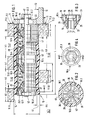
- Fig. 1 shows a dowel attachment in hollow bricks 11.1 and 11.2 with a dowel 10, to which a support bracket 12 is attached for a step, not shown, which acts on the support bracket 12 and the dowel attachment with the load indicated by the arrow 13.
- the hollow bricks 11 form a wall surface 15 on which the leg 12.1 of the support bracket 12 lies smoothly.
- This wall surface 15 formed with a plurality of hollow bricks is the wall surface of a stairwell wall and is constructed in a conventional manner.
- three webs of a first possible hollow brick 11.1 and in the lower part two webs of another hollow brick 11.2 with very large hollow chambers are indicated.
- These Different hollow bricks do not naturally occur on a dowel, but it is only intended to clarify how the dowel according to the invention can be used with very different hollow bricks and can carry safely in the hollow chambers even with large free lengths.
- Both hollow bricks 11.1 and 11.2 have the same design and lying outer webs 11.3. These form the wall surface 15 and have a width a.
- a first cavity 11.41 adjoins the outer web 11.3 and has a width h1 in the hollow chamber stone 11.1 in the upper part of FIG. 1.
- the second web 11.51 with a width b1.
- the second cavity 11.42 with a width h2.
- the third web 11.6 with a width b3.
- the cavity 11.43 is substantially wider than the cavity 11.41 in the upper part of the figure and has the width h3.
- a further cavity 11.7 with a width h4 adjoins the second web 11.52 with the width b2. the limitation of which is no longer shown.
- the third web 11.6 can already limit the opposite wall surface in the case of thin walls, for example 17.5 cm thick.
- the drilled hole can then be plastered.
- the bore 14 extends through all the webs shown. It is created in the usual way with a drill bit.
- the dowel 10 is inserted into this bore 14.
- the dowel 10 has a plastic tube 40 extending over its entire length L on the outside. It has a wall thickness 41 of approximately 5 mm, for example. Bore 14 and plastic tube 40 have an initial diameter D of, for example, approximately 50 mm.
- the length L is, for example, approximately 16.5 cm.
- the plastic tube 40 is provided with a slot 47 (FIG. 2), preferably continuous over its entire length, so that it can follow the spreading movements and deformations.
- a slot 47 (FIG. 2), preferably continuous over its entire length, so that it can follow the spreading movements and deformations.
- its material properties are to be determined above all in such a way that it has sufficient rigidity for force-controlled spreading and can serve as the bridging dealt with below.
- the plastic tube 40 there are two ring segment cylinders 10.5 and 10.6 with four clamping parts 10.4. They are penetrated by a clamping bolt 42, which has threads at least at its ends and is screwed onto the hexagon nuts 43.1 and 43.2, the nut 43.2 being located on the wall leg 12.1 of the support bracket 12 at the edges of an elongated hole 12.2 made in the latter via a washer 44 supports.
- the clamping parts 10.4 are made with approximately the same wall thickness in the injection molding process from glass fiber reinforced polyamide - as described in DE-OS 32 18 457 - or from a suitable metal in the die casting process. They each have an outer cone 16 which is formed with a smooth conical surface. The cone angle is indicated at 17. Cavities 19 protrude from the end face 18 into the clamping part 10.4 in the outer region, so that the same wall thicknesses are formed for production.
- a receiving recess 20 for a hexagon nut with suitable external dimensions and suitable depth is formed centrally.
- An M10 hex nut is provided here.
- a central bore 21 has in the region of the cone 16 only six ribs 22 pointing to the corners of the receiving recess 20 designed as a hexagon, with which the clamping part 10.4 is centered on the clamping bolt 42.
- the hexagon nut 43.1 lies in the receiving recess 20 of the end clamping part 10.41, while the other end clamping part 10.42 extends to the wall surface 15 so that it is supported on the wall leg 12.1 of the support bracket 12. No mother is inserted here.
- each ring segment cylinder 10.5 or 10.6 form a coherent unit which is equipped with predetermined breaking points 35.
- each ring segment cylinder 10.5 or 10.6 have inside conical surfaces 25 which are formed on the ends of their inner longitudinal ribs 29.
- the ring segment cylinder 10.5 and 10.6 are made in one piece and have in their longitudinal center inside a transverse rib 33 up to which the integrally molded longitudinal ribs 29 extend so that the injection molding tools can engage from both ends.
- the conical surfaces 25 only have a continuous ring region 25.1 on the outside, the wall thickness of which corresponds to that of the partial cylinder walls 28 of the ring segment clamping shells 10.1 to 10.3 and which preferably merges into the end surfaces of the longitudinal ribs 29 at the same angle.
- the longitudinal ribs 29 form a space between them for the passage of the clamping bolt 42.
- the relatively high longitudinal ribs 29 lead to a favorable flexural strength of the ring segment clamping shells 10.1 to 10.3, which after the breaking apart of the predetermined breaking points 35 also spread in the end regions, as schematically indicated, can deform depending on the outer support.
- the arch-like design of the partial cylinder walls 28 of the ring segment clamping shells 10.1 to 10.3 results in favorable stiffness and strength properties, to which the central transverse rib contributes significantly.
- conical surfaces at the ends of the longitudinal ribs 29 other wedge surface shapes corresponding to the wedge ratios when pressed together can also be selected.
- All wall thicknesses of the outer walls, the cone parts, ribs and the like are approximately 1.5 to 2 mm if a glass fiber reinforced polyamide is used. Suitable metal die-casting materials can, however, also be used, provided the necessary deformations can be achieved.
- clamping parts 10.4 from metal and the ring segment clamping shells 10.1 to 10.3 from glass fiber reinforced plastic.
- the materials are to be coordinated with the outer plastic tube 40.
- Suitable measures are to be taken to prevent the components of the dowel 10 from rotating with respect to one another and against the wall.
- at least one fixing pin 36 protrudes from the conical surface of each clamping part 10.4. They engage between the longitudinal ribs 29 of the ring segment clamping shells 10.1 to 10.3.
- the ring segment clamping shells 10.1 to 10.3 have the usual holding profiles 27 on their outer surfaces 26.
- the plastic tube 40 is provided on the inside with similar profiles, not shown, so that the two profiles interlock.
- the plastic pipe 40 is likewise provided on its outer surface 45 with suitable profiles 46.
- the ring segment clamping shells 10.1 to 10.3 are not only pressed apart in the end regions, but that clamping parts are also provided in intermediate regions and the ring segment clamping shells 10.1 to 10.3 therefore do not extend over the entire length L of the Dowel 10 or Extend plastic tube 40, but only have a ring segment clamping shell length 30, which makes up a small part of the same.
- the ring segment clamping shell length 30 is approximately 60 mm.
- the diameter of the cylindrical shaft 23 of the clamping part 10.4 is approximately 40 mm, its length is approximately 10 mm.
- the ring segment clamping shell which is to be located further outwards, always lies with certainty within the outer wall surface 15.
- two complete inner dowels with ring segment clamping shells and clamping parts are installed one behind the other in the plastic tube 40.
- Such dowels can otherwise be used for conventional heavy-duty assemblies in the known manner.
- the dowels 10 according to the invention can only be constructed from the same tools with little production and storage expenditure by using an additional slotted plastic tube 40.
- the use of two ring segment clamping shells with lengths of 60 mm is expedient for all hollow chamber stones that are currently under consideration, including those that have very large cavities and are made, for example, of sand-lime brick material.
- the ring segment clamping shells can now in no case avoid that the clamping parts 10.4 would pull completely into them, because the plastic tube 40 always finds a hold somewhere and is sufficient in the rest is stiff.
- the differently spaced webs in the two parts of FIG. 1 illustrate that even in cases in which the ends of the ring segment clamping shells no longer lie in the support region of the webs, a very good hold is still achieved. Due to the large length L of the dowel 10 and the favorable position of the inner web 11.5, even in such a hollow chamber stone 11.2 it is still possible to fasten a stair step with not too great a load with only one dowel 10.
- the dowel (10) has ring segment clamping shells (10.1, 10.2, 10.3) which are pressed apart by clamping parts (10.4) when the clamping bolt (42) is tightened using the hexagon nuts (43.1, 43.2).
- a plastic tube (40) inserted over the ring segment clamping shells prevents the ends of the ring segment clamping shells from opening apart if they cannot find a hold in cavities (11.41, 11.42).
Landscapes
- Engineering & Computer Science (AREA)
- General Engineering & Computer Science (AREA)
- Architecture (AREA)
- Mechanical Engineering (AREA)
- Civil Engineering (AREA)
- Structural Engineering (AREA)
- Mutual Connection Of Rods And Tubes (AREA)
- Steps, Ramps, And Handrails (AREA)
- Table Equipment (AREA)
- Clamps And Clips (AREA)
Priority Applications (1)
| Application Number | Priority Date | Filing Date | Title |
|---|---|---|---|
| AT91106746T ATE97717T1 (de) | 1990-05-12 | 1991-04-26 | Duebelbefestigung fuer tragteile von treppenstufen oder fuer aehnliche schwere bauteile. |
Applications Claiming Priority (2)
| Application Number | Priority Date | Filing Date | Title |
|---|---|---|---|
| DE4015278 | 1990-05-12 | ||
| DE4015278A DE4015278A1 (de) | 1990-05-12 | 1990-05-12 | Duebelbefestigung fuer tragteile von treppenstufen oder fuer aehnliche schwere bauteile |
Publications (2)
| Publication Number | Publication Date |
|---|---|
| EP0457080A1 true EP0457080A1 (fr) | 1991-11-21 |
| EP0457080B1 EP0457080B1 (fr) | 1993-11-24 |
Family
ID=6406259
Family Applications (1)
| Application Number | Title | Priority Date | Filing Date |
|---|---|---|---|
| EP91106746A Expired - Lifetime EP0457080B1 (fr) | 1990-05-12 | 1991-04-26 | Fixation de cheville pour éléments porteurs de marches d'escalier ou pour éléments similaires de construction lourde |
Country Status (3)
| Country | Link |
|---|---|
| EP (1) | EP0457080B1 (fr) |
| AT (1) | ATE97717T1 (fr) |
| DE (2) | DE4015278A1 (fr) |
Families Citing this family (1)
| Publication number | Priority date | Publication date | Assignee | Title |
|---|---|---|---|---|
| DE202006017696U1 (de) * | 2006-11-21 | 2008-01-03 | Grünewald, Robin | Schwerlastdübel, insbesondere zur Halterung der Treppenstufen einer Bolzentreppe an einer Baufläche |
Citations (1)
| Publication number | Priority date | Publication date | Assignee | Title |
|---|---|---|---|---|
| DE3218457A1 (de) * | 1982-05-15 | 1983-11-17 | Neucon Maschinen- Und Bausysteme Gmbh U. Co Kg, 7100 Heilbronn | Duebelbefestigung fuer treppenstufen |
Family Cites Families (2)
| Publication number | Priority date | Publication date | Assignee | Title |
|---|---|---|---|---|
| SE389715B (sv) * | 1972-11-01 | 1976-11-15 | Herbacks Ind Ab | Expanderbult |
| DE2626494C2 (de) * | 1976-06-12 | 1986-11-20 | Hilti Ag, Schaan | Verwendung eines Dübels |
-
1990
- 1990-05-12 DE DE4015278A patent/DE4015278A1/de not_active Withdrawn
-
1991
- 1991-04-26 AT AT91106746T patent/ATE97717T1/de not_active IP Right Cessation
- 1991-04-26 DE DE91106746T patent/DE59100627D1/de not_active Expired - Fee Related
- 1991-04-26 EP EP91106746A patent/EP0457080B1/fr not_active Expired - Lifetime
Patent Citations (1)
| Publication number | Priority date | Publication date | Assignee | Title |
|---|---|---|---|---|
| DE3218457A1 (de) * | 1982-05-15 | 1983-11-17 | Neucon Maschinen- Und Bausysteme Gmbh U. Co Kg, 7100 Heilbronn | Duebelbefestigung fuer treppenstufen |
Also Published As
| Publication number | Publication date |
|---|---|
| DE4015278A1 (de) | 1991-11-14 |
| EP0457080B1 (fr) | 1993-11-24 |
| DE59100627D1 (de) | 1994-01-05 |
| ATE97717T1 (de) | 1993-12-15 |
Similar Documents
| Publication | Publication Date | Title |
|---|---|---|
| DE10035580B4 (de) | Formschlüssig setzbarer Hinterschneid-Anker | |
| DE2256938B2 (de) | Einsatzhülse für Gipswände o.dgl | |
| EP0008085B1 (fr) | Cheville | |
| DE4030978C2 (de) | Verbindungseinrichtung für Rohre | |
| DE2334763C2 (de) | Dübel | |
| AT392130B (de) | Befestigungselement | |
| DE19642914C2 (de) | Dübel | |
| EP0004374B1 (fr) | Moyen de liaison de deux profilés | |
| EP0015895B1 (fr) | Tirant pour l'ancrage d'éléments de construction dans un corps de fondement | |
| EP0529229B1 (fr) | Chevilles murales | |
| DE1775527A1 (de) | Mehrteiliger Spreizduebel | |
| DE4231313C2 (de) | Spreizdübel | |
| EP0457080B1 (fr) | Fixation de cheville pour éléments porteurs de marches d'escalier ou pour éléments similaires de construction lourde | |
| DE2655728A1 (de) | Loesbare naben-wellenverbindung | |
| EP0693162B1 (fr) | Cheville d'expansion | |
| DE3921733A1 (de) | Befestigungsanker fuer die verankerung in einem bohrloch eines mauerwerks | |
| WO1985003332A1 (fr) | Cheville de fermeture de moule pour du beton | |
| DE2741422A1 (de) | Spreizduebel | |
| EP0964169B1 (fr) | Cheville pour cadres | |
| DE4344344C2 (de) | Kamin mit mehreren, durch Verbindungsanordnungen biegesteif miteinander verbundenen Kaminelementen | |
| DE2229657B2 (de) | Montageplatte fuer moebelscharniere | |
| DE3218457C2 (de) | Dübelbefestigung für Treppenstufen | |
| EP2565470B1 (fr) | Cheville | |
| DE3426288C2 (de) | Spreizdübel aus Metallblech | |
| AT399374B (de) | Kunststoffspreizdübel für die verankerung in mauerwerk, betonteilen oder dgl. |
Legal Events
| Date | Code | Title | Description |
|---|---|---|---|
| PUAI | Public reference made under article 153(3) epc to a published international application that has entered the european phase |
Free format text: ORIGINAL CODE: 0009012 |
|
| AK | Designated contracting states |
Kind code of ref document: A1 Designated state(s): AT BE CH DE DK ES FR GB GR IT LI LU NL SE |
|
| 17P | Request for examination filed |
Effective date: 19920116 |
|
| 17Q | First examination report despatched |
Effective date: 19930413 |
|
| GRAA | (expected) grant |
Free format text: ORIGINAL CODE: 0009210 |
|
| AK | Designated contracting states |
Kind code of ref document: B1 Designated state(s): AT BE CH DE DK ES FR GB GR IT LI LU NL SE |
|
| PG25 | Lapsed in a contracting state [announced via postgrant information from national office to epo] |
Ref country code: IT Free format text: LAPSE BECAUSE OF FAILURE TO SUBMIT A TRANSLATION OF THE DESCRIPTION OR TO PAY THE FEE WITHIN THE PRE;WARNING: LAPSES OF ITALIAN PATENTS WITH EFFECTIVE DATE BEFORE 2007 MAY HAVE OCCURRED AT ANY TIME BEFORE 2007. THE CORRECT EFFECTIVE DATE MAY BE DIFFERENT FROM THE ONE RECORDED.SCRIBED TIME-LIMIT Effective date: 19931124 Ref country code: DK Effective date: 19931124 Ref country code: SE Effective date: 19931124 Ref country code: GR Free format text: LAPSE BECAUSE OF FAILURE TO SUBMIT A TRANSLATION OF THE DESCRIPTION OR TO PAY THE FEE WITHIN THE PRESCRIBED TIME-LIMIT Effective date: 19931124 Ref country code: ES Free format text: THE PATENT HAS BEEN ANNULLED BY A DECISION OF A NATIONAL AUTHORITY Effective date: 19931124 Ref country code: BE Effective date: 19931124 |
|
| REF | Corresponds to: |
Ref document number: 97717 Country of ref document: AT Date of ref document: 19931215 Kind code of ref document: T |
|
| REF | Corresponds to: |
Ref document number: 59100627 Country of ref document: DE Date of ref document: 19940105 |
|
| GBT | Gb: translation of ep patent filed (gb section 77(6)(a)/1977) |
Effective date: 19940126 |
|
| ET | Fr: translation filed | ||
| PG25 | Lapsed in a contracting state [announced via postgrant information from national office to epo] |
Ref country code: LU Free format text: LAPSE BECAUSE OF NON-PAYMENT OF DUE FEES Effective date: 19940430 |
|
| PLBE | No opposition filed within time limit |
Free format text: ORIGINAL CODE: 0009261 |
|
| STAA | Information on the status of an ep patent application or granted ep patent |
Free format text: STATUS: NO OPPOSITION FILED WITHIN TIME LIMIT |
|
| 26N | No opposition filed | ||
| PGFP | Annual fee paid to national office [announced via postgrant information from national office to epo] |
Ref country code: NL Payment date: 20010430 Year of fee payment: 11 |
|
| REG | Reference to a national code |
Ref country code: GB Ref legal event code: IF02 |
|
| PGFP | Annual fee paid to national office [announced via postgrant information from national office to epo] |
Ref country code: AT Payment date: 20020404 Year of fee payment: 12 |
|
| PGFP | Annual fee paid to national office [announced via postgrant information from national office to epo] |
Ref country code: FR Payment date: 20020405 Year of fee payment: 12 |
|
| PGFP | Annual fee paid to national office [announced via postgrant information from national office to epo] |
Ref country code: GB Payment date: 20020424 Year of fee payment: 12 |
|
| PGFP | Annual fee paid to national office [announced via postgrant information from national office to epo] |
Ref country code: CH Payment date: 20020709 Year of fee payment: 12 |
|
| PG25 | Lapsed in a contracting state [announced via postgrant information from national office to epo] |
Ref country code: NL Free format text: LAPSE BECAUSE OF NON-PAYMENT OF DUE FEES Effective date: 20021101 |
|
| NLV4 | Nl: lapsed or anulled due to non-payment of the annual fee |
Effective date: 20021101 |
|
| PG25 | Lapsed in a contracting state [announced via postgrant information from national office to epo] |
Ref country code: GB Free format text: LAPSE BECAUSE OF NON-PAYMENT OF DUE FEES Effective date: 20030426 Ref country code: AT Free format text: LAPSE BECAUSE OF NON-PAYMENT OF DUE FEES Effective date: 20030426 |
|
| PG25 | Lapsed in a contracting state [announced via postgrant information from national office to epo] |
Ref country code: LI Free format text: LAPSE BECAUSE OF NON-PAYMENT OF DUE FEES Effective date: 20030430 Ref country code: CH Free format text: LAPSE BECAUSE OF NON-PAYMENT OF DUE FEES Effective date: 20030430 |
|
| REG | Reference to a national code |
Ref country code: CH Ref legal event code: PL |
|
| GBPC | Gb: european patent ceased through non-payment of renewal fee | ||
| PG25 | Lapsed in a contracting state [announced via postgrant information from national office to epo] |
Ref country code: FR Free format text: LAPSE BECAUSE OF NON-PAYMENT OF DUE FEES Effective date: 20031231 |
|
| REG | Reference to a national code |
Ref country code: FR Ref legal event code: ST |
|
| PGFP | Annual fee paid to national office [announced via postgrant information from national office to epo] |
Ref country code: DE Payment date: 20060424 Year of fee payment: 16 |
|
| PG25 | Lapsed in a contracting state [announced via postgrant information from national office to epo] |
Ref country code: DE Free format text: LAPSE BECAUSE OF NON-PAYMENT OF DUE FEES Effective date: 20071101 |