EP0457086B1 - Mesure sans contact de propagation du couple locale sur des machines à vis sans fin - Google Patents
Mesure sans contact de propagation du couple locale sur des machines à vis sans fin Download PDFInfo
- Publication number
- EP0457086B1 EP0457086B1 EP91106868A EP91106868A EP0457086B1 EP 0457086 B1 EP0457086 B1 EP 0457086B1 EP 91106868 A EP91106868 A EP 91106868A EP 91106868 A EP91106868 A EP 91106868A EP 0457086 B1 EP0457086 B1 EP 0457086B1
- Authority
- EP
- European Patent Office
- Prior art keywords
- worm
- der
- measuring
- local
- torque
- Prior art date
- Legal status (The legal status is an assumption and is not a legal conclusion. Google has not performed a legal analysis and makes no representation as to the accuracy of the status listed.)
- Expired - Lifetime
Links
- 238000005259 measurement Methods 0.000 title claims description 23
- 238000000034 method Methods 0.000 claims description 31
- 230000008569 process Effects 0.000 claims description 17
- 239000000463 material Substances 0.000 claims description 7
- 238000004458 analytical method Methods 0.000 claims description 4
- 238000011144 upstream manufacturing Methods 0.000 claims 1
- 238000011156 evaluation Methods 0.000 description 8
- 238000006243 chemical reaction Methods 0.000 description 7
- 230000008901 benefit Effects 0.000 description 6
- 238000006073 displacement reaction Methods 0.000 description 5
- 230000008859 change Effects 0.000 description 3
- 230000008878 coupling Effects 0.000 description 3
- 238000010168 coupling process Methods 0.000 description 3
- 238000005859 coupling reaction Methods 0.000 description 3
- 238000005516 engineering process Methods 0.000 description 3
- 238000004886 process control Methods 0.000 description 3
- 241000393427 Cepaea hortensis Species 0.000 description 2
- 238000010586 diagram Methods 0.000 description 2
- 230000001939 inductive effect Effects 0.000 description 2
- 238000004898 kneading Methods 0.000 description 2
- 230000000737 periodic effect Effects 0.000 description 2
- 210000002023 somite Anatomy 0.000 description 2
- 239000000126 substance Substances 0.000 description 2
- 239000000853 adhesive Substances 0.000 description 1
- 230000001070 adhesive effect Effects 0.000 description 1
- 230000005540 biological transmission Effects 0.000 description 1
- 238000004364 calculation method Methods 0.000 description 1
- 238000005352 clarification Methods 0.000 description 1
- 238000004891 communication Methods 0.000 description 1
- 238000007906 compression Methods 0.000 description 1
- 238000010276 construction Methods 0.000 description 1
- 238000007796 conventional method Methods 0.000 description 1
- 238000001816 cooling Methods 0.000 description 1
- 230000003111 delayed effect Effects 0.000 description 1
- 230000001419 dependent effect Effects 0.000 description 1
- 238000013461 design Methods 0.000 description 1
- 238000001514 detection method Methods 0.000 description 1
- 238000010438 heat treatment Methods 0.000 description 1
- 230000004807 localization Effects 0.000 description 1
- 230000007257 malfunction Effects 0.000 description 1
- 238000004519 manufacturing process Methods 0.000 description 1
- 238000011089 mechanical engineering Methods 0.000 description 1
- 230000003287 optical effect Effects 0.000 description 1
- 230000000704 physical effect Effects 0.000 description 1
- 238000012545 processing Methods 0.000 description 1
- 230000001105 regulatory effect Effects 0.000 description 1
- 230000000246 remedial effect Effects 0.000 description 1
- 238000010079 rubber tapping Methods 0.000 description 1
- 230000035945 sensitivity Effects 0.000 description 1
- 230000009466 transformation Effects 0.000 description 1
- 238000002604 ultrasonography Methods 0.000 description 1
Images

Classifications
-
- G—PHYSICS
- G01—MEASURING; TESTING
- G01L—MEASURING FORCE, STRESS, TORQUE, WORK, MECHANICAL POWER, MECHANICAL EFFICIENCY, OR FLUID PRESSURE
- G01L3/00—Measuring torque, work, mechanical power, or mechanical efficiency, in general
- G01L3/02—Rotary-transmission dynamometers
- G01L3/04—Rotary-transmission dynamometers wherein the torque-transmitting element comprises a torsionally-flexible shaft
- G01L3/10—Rotary-transmission dynamometers wherein the torque-transmitting element comprises a torsionally-flexible shaft involving electric or magnetic means for indicating
-
- A—HUMAN NECESSITIES
- A21—BAKING; EDIBLE DOUGHS
- A21C—MACHINES OR EQUIPMENT FOR MAKING OR PROCESSING DOUGHS; HANDLING BAKED ARTICLES MADE FROM DOUGH
- A21C1/00—Mixing or kneading machines for the preparation of dough
- A21C1/14—Structural elements of mixing or kneading machines; Parts; Accessories
- A21C1/145—Controlling; Testing; Measuring
- A21C1/1455—Measuring data of the driving system, e.g. torque, speed, power
-
- G—PHYSICS
- G01—MEASURING; TESTING
- G01L—MEASURING FORCE, STRESS, TORQUE, WORK, MECHANICAL POWER, MECHANICAL EFFICIENCY, OR FLUID PRESSURE
- G01L3/00—Measuring torque, work, mechanical power, or mechanical efficiency, in general
Definitions
- the invention is based on a screw machine with a device for measuring the torque input in the product space.
- Measurements on rotating shafts to determine the torque input essentially use two methods.
- the first method is done using strain gauges that are glued to the rotating shaft.
- the second method is to apply two additional marks on the shaft (e.g. gears, additional disks), see U.S. Patent 3,589,178 or U.S. Patent 3,604,255, which induce periodic signals in stationary sensors. Both methods can be used on screw machines without affecting the product space if the measuring element or markings are outside the product space.
- the strain gauges are usually attached to the coupling between the drive unit and the actual system and are used in this case to measure the total input torque.
- the moment distribution along the screw remains unknown and cannot be calculated from this measurement.
- a measurement with strain gauges arranged along the screw encounters considerable difficulties with regard to their applicability in practice. These difficulties are due to the fact that the strain gauges are glued on so that the There are limits to the applicability of this method due to the temperature resistance of the adhesive used.
- there is the blatant disadvantage that an intervention in the geometry of the body to be measured must take place in every case, be it to lead out the measuring cable or to create the cheapest measuring location.
- a suitable measuring location is often not representative, while conversely a representative measuring location is inaccessible due to the construction of the machine.
- the underlying task is to develop a measuring technique in connection with a screw machine which, under operating conditions and without additional mechanical engineering intervention, allows the determination of the local torque curve in the axial direction of the screw.
- the locally entered moment means the mechanical power converted into thermal and kinetic energy at a discrete location of the screw.
- the locally entered torque depends, among other things, on the locally prevailing characteristic process variables, such as viscosity, conversion.
- a measurement of the locally entered torque could therefore be used to infer the process variables prevailing at the measurement location and, in turn, the local composition of the product transported through the machine. In this way, one could receive information about the ongoing process and take specific measures for regulation, for example with a view to optimal economy.
- Non-contact scanning sensors are arranged in the screw housing, each of which emits one or more electrical measuring pulses when the screw shaft rotates, and the sensors are connected to an evaluation circuit for determining the time differences between the measuring pulses.
- the surface profile or the surface structure of the screw is scanned with a suitable sensor in such a way that a function which is significant for this surface is obtained, which is the distance between the sensor and the screw surface over time, i.e. over the angle of rotation of the screw.
- sensors are e.g. inductive displacement sensors.
- the curve obtained in this way represents a kind of "fingerprint" of the screw surface rotating under the sensor. If the assignment of said curve and the surface structure is difficult, suitable, precisely assignable significance can be created with suitable marking elements (notches or the like). The dimensions of these significance can be chosen based on the sensitivity of the sensors so that they do not affect the processes in the process space. Furthermore, it is conceivable to view the surface curve only at a discrete point, e.g. snail comb or screw flank, and only to locate it sensitively, since the surface curve itself does not change in its absolute form, but only shifts relative to the time axis due to a wave torsion. A proximity switch would already be sufficient to fulfill this measuring function.
- a discrete point e.g. snail comb or screw flank
- the time differences between the surface curves delayed by the torsion and their reference curves for a non-twisted shaft are evaluated. This applies to both types of localization of the surface curve described above.
- the time differences can be viewed as a direct measure of the torsion angle between the start of the shaft and the measuring location by converting it into a distance, while knowing the current speed and some material and geometry sizes of the shaft. If several sensors are used in the axial direction, a section-wise torsion angle course and thus the sectionally entered torque can be determined by forming the difference. This could provide information about the chemical or technological process taking place. If several sensors are used in the radial direction, suitable evaluation methods such as Fourier analysis or the like, torsional vibrations can be detected.
- the maximum possible resolution is a known function of the radial offset and the speed of the shafts. It is advantageous to additionally arrange a position angle transmitter for measuring the angle of the screw at the end of the screw. Furthermore, a measuring unit (sensor with associated marking element on the screw) is expediently arranged before the screw shaft enters the product space in order to generate a reference pulse in the region of the screw shaft which is still unloaded.
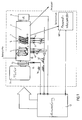
- the worm shaft 1 in the product space 2 of the worm machine is driven by an electric motor 3.
- Two different process sections 4 and 5 are indicated along the worm shaft.
- the first section 4 e.g. an intensive mixing of the material by means of kneading disks and in the second section 5 a compression process with predominantly axial conveyance takes place.
- a position angle sensor 6 can be arranged, which allows an additional angle measurement.
- the screw space (screw flank) 7 in the process section 5 and the kneading disks 8 in the process section 4 are provided with measuring notches 9. These additional measuring notches are only necessary if it is difficult to assign the surface profile to the measuring curve.
- Fixed, contactlessly scanning sensors 11 are arranged in the worm housing 10 and scan the worm surface with every revolution of the worm shaft 1.
- Standard capacitive, inductive, optical sensors or sensors based on ultrasound or eddy currents, non-contact displacement sensors or proximity switches are suitable as sensors.
- Such transducers deliver an analog signal that is proportional to the distance from the opposite surface. In the case of a measurement notch 9, this distance is increased abruptly, which has a strong influence on the gradient of the analog output signal from sensor 11.
- An evaluation unit 12 connected downstream of the sensors emits a rectangular pulse precisely when the evaluation unit has received reliable information from the sensor signal that a characteristic of the surface curve has occurred.
- the possibly very small signals can possibly be amplified by a measuring amplifier 13.
- a separate measuring unit 15 is attached to the screw 14 on the coupling 14 for the drive 3 and supplies a reference pulse 16 from a point on the screw machine at which the shaft 1 does not yet have any torsion. This reference pulse 16 is referred to below as the master pulse.
- the total torsion angle of the worm shaft 1 is detected during operation by the separately mounted position angle transmitter 6 and measured directly.
- the amplified measuring pulses 17, the master pulse 16 and the measuring signal coming from the position angle transmitter 6 are fed to an evaluation unit (arithmetic unit), for example a measuring computer (not shown), which takes over the further processing of the measured values.
- the functions of the evaluation unit (not shown), the measuring amplifier and the measurement signal tracking can possibly be carried out by a powerful measuring computer.
- the measuring cycle preferably begins with the evaluation unit receiving the master pulse 16 and first of all recording the current position angle supplied by the angle transmitter 6 and at the same time resetting and starting a timer.
- the incoming pulses of the individual measuring sensors 11 each trigger a routine that converts the time that has elapsed since the timer started into the angular offset existing with respect to the clutch 14, or directly determines the offset angle values of two successive measuring pulses.
- a dimensionless angle and a dimensionless length can be formed by relating the individual measured angles to the total angle initially determined and the individual distances of the measuring units from the start of the screw to the total length of the screw.
- a dimensionless torque results if the total torque measured on the coupling of the worm is related to the torque entered up to a specific measuring unit. From the knowledge of the partial torques entered up to each measuring unit (sensor 11), the torques entered locally between the measuring units can be calculated by subtraction. The denser the network of measuring units or sensors 11, the more precisely the torque curve can be determined. From the moment, the local viscosity of the material transported by the screw machine can be closed when the product viscosity is measured online with a process rheometer 18 connected to the product space 2.
- Viscosity locus curves of this type have so far not been accessible in terms of measurement technology in screw machines.
- the time difference ⁇ t between the measuring pulse coming from a sensor i and the next sensor i + 1 is entered in the pulse-time diagram according to FIG. 2.
- the measurement of the time difference .DELTA.t takes place in a conventional manner in that a timer is activated by the first pulse 17a, which emits counting pulses until the second pulse 17b arrives.
- the time difference to the master pulse can be determined in an analogous manner. If the instantaneous speed of the worm shaft is known, the angle swept during the time period ⁇ t can then be calculated. This swept angle corresponds to the torsion angle of the shaft in the relevant measuring section, provided that the characteristics of the shaft surfaces, e.g. Snail comb or worm flank or possibly additional measuring notches are in alignment. If the arrangement is not aligned, the offset angle must be determined beforehand. If the torsional behavior of the worm shaft 1 is additionally known, the torque introduced between these two measuring units (i and i + 1) can be calculated, which is assigned to the measured torsional angle.
Landscapes
- Physics & Mathematics (AREA)
- General Physics & Mathematics (AREA)
- Life Sciences & Earth Sciences (AREA)
- Biophysics (AREA)
- Engineering & Computer Science (AREA)
- Food Science & Technology (AREA)
- Testing Of Devices, Machine Parts, Or Other Structures Thereof (AREA)
- Length Measuring Devices With Unspecified Measuring Means (AREA)
Claims (6)
- Machine à vis d'Archimède comportant un dispositif de mesure du couple appliqué, caractérisé en ce que dans le boîtier (10) de la vis d'Archimède sont agencés au moins deux capteurs de déplacement ou détecteurs de proximité (11) mesurant sans contact, qui balayent pendant la rotation de l'arbre (1) de la vis d'Archimède la surface de l'arbre de la vis d'Archimède et engendrent sur la base de caractéristiques détectées des impulsions de mesure qui peuvent être amenées conjointement avec un signal de vitesse de rotation à un circuit d'évaluation (12) électronique qui, en liaison avec un dispositif de mesure du couple intégral agencé entre l'entraînement (3) de l'arbre de la vis d'Archimède et un espace du produit de la machine à vis d'Archimède détermine le couple local, appliqué dans un segment de l'arbre de la vis d'Archimède, à l'intérieur de l'espace du produit.
- Machine à vis d'Archimède selon la revendication 1, caractérisée en ce que les couples appliqués localement peuvent être comparés à des valeurs de consigne et automatiquement régulés.
- Machine à vis d'Archimède selon la revendication 2, caractérisée en ce que le flux de matériau et/ou la vitesse de rotation sont utilisés comme paramètres de consigne pour la régulation.
- Machine à vis d'Archimède selon l'une quelconque des revendications 1 à 3, caractérisée en ce que l'espace du produit est en liaison avec un rhéomètre (18) de process et en ce qu'à l'aide du circuit d'évaluation, les viscosités locales peuvent être déterminées dans les différents segments de l'arbre de la vis d'Archimède.
- Machine à vis d'Archimède selon l'une quelconque des revendications 1 à 4, caractérisée en ce qu'une unité de mesure séparée (15) est agencée avant l'entrée de l'arbre (1) de la vis d'Archimède dans l'espace du produit (2) pour engendrer dans la région de tous les arbres de vis d'Archimède non surchargés une impulsion de référence (16) qui peut être amenée au circuit d'évaluation pour déterminer le couple intégral local sans dimension et pour déterminer la viscosité.
- Machine à vis d'Archimède selon l'une quelconque des revendications 1 à 5, caractérisée en ce que les éléments de marquage sont constitués par des entailles ou des gorges (9) étroitement limitées dans l'espace dans la bordure de la vis d'Archimède.
Applications Claiming Priority (2)
| Application Number | Priority Date | Filing Date | Title |
|---|---|---|---|
| DE4015295 | 1990-05-12 | ||
| DE4015295A DE4015295A1 (de) | 1990-05-12 | 1990-05-12 | Beruehrungslose messung des lokalen drehmomenteintrages an schneckenmaschinen |
Publications (3)
| Publication Number | Publication Date |
|---|---|
| EP0457086A2 EP0457086A2 (fr) | 1991-11-21 |
| EP0457086A3 EP0457086A3 (en) | 1992-12-09 |
| EP0457086B1 true EP0457086B1 (fr) | 1994-09-14 |
Family
ID=6406266
Family Applications (1)
| Application Number | Title | Priority Date | Filing Date |
|---|---|---|---|
| EP91106868A Expired - Lifetime EP0457086B1 (fr) | 1990-05-12 | 1991-04-27 | Mesure sans contact de propagation du couple locale sur des machines à vis sans fin |
Country Status (2)
| Country | Link |
|---|---|
| EP (1) | EP0457086B1 (fr) |
| DE (2) | DE4015295A1 (fr) |
Cited By (1)
| Publication number | Priority date | Publication date | Assignee | Title |
|---|---|---|---|---|
| DE102017009046A1 (de) * | 2017-09-27 | 2019-03-28 | Reifenhäuser GmbH & Co. KG Maschinenfabrik | Zustandsüberwachungssystem, verfahren zum bestimmen eines abnutzungsgrads, wartungssteuerungsverfahren, betriebsführungs- und sicherheitssystem und extruder |
Families Citing this family (6)
| Publication number | Priority date | Publication date | Assignee | Title |
|---|---|---|---|---|
| DE19515130A1 (de) * | 1995-04-25 | 1996-10-31 | Werner & Pfleiderer | Einrichtung zur Messung des Drehmomenteintrages bei Mehrwellenextrudern |
| IL124932A0 (en) * | 1998-06-16 | 1999-01-26 | Mea Motor Inspection Ltd | Method and apparatus for testing rotating machines |
| DE10008531A1 (de) * | 2000-02-24 | 2001-09-13 | List Ag Arisdorf | Verfahren zum Behandeln eines Produktes in zumindest einem Mischkneter |
| DE10303167B4 (de) * | 2003-01-27 | 2006-01-12 | List Holding Ag | Verfahren zur kontinuierlichen Phasenumwandlung eines Produktes |
| EP3955842A4 (fr) * | 2019-04-15 | 2023-01-11 | Covidien LP | Procédé d'étalonnage de capteurs de couple d'unités d'entraînement d'instrument d'un robot chirurgical |
| AT527588B1 (de) * | 2024-01-18 | 2025-04-15 | Pro2Future Gmbh | Verfahren zur Bestimmung des axialen Drehmomentenverlaufes in Schneckenextrudern |
Family Cites Families (10)
| Publication number | Priority date | Publication date | Assignee | Title |
|---|---|---|---|---|
| DE720181C (de) * | 1940-07-18 | 1942-04-27 | Wilhelm Koreska | Viskosimeter mit Foerderschnecke |
| SE321811B (fr) * | 1966-03-16 | 1970-03-16 | Jungner Instrument Ab | |
| GB1201310A (en) * | 1966-09-27 | 1970-08-05 | Rolls Royce | Electrical pulse transmitting apparatus |
| AT280656B (de) * | 1968-02-19 | 1970-04-27 | H C Hans Dipl Ing Dr Dr List | Schaltungsanordnung zur Messung des Verdrehwinkels |
| US3604255A (en) * | 1970-02-20 | 1971-09-14 | Teledyne Ind | Power meter for rotating shafts and method of providing power readout therefor |
| DE2435709C2 (de) * | 1974-07-25 | 1985-05-30 | Robert Bosch Gmbh, 7000 Stuttgart | Einrichtung zur Überprüfung von berührungslos arbeitenden Drehmomentmeßeinrichtungen |
| DE2557066C2 (de) * | 1975-12-18 | 1986-05-15 | Klöckner-Humboldt-Deutz AG, 5000 Köln | Verfahren zur Messung der Drehzahldifferenz zwischen losen Laufringen und einer in diesen gelagerten Drehtrommel sowie Vorrichtung zur Durchführung des Verfahrens |
| DE2928155A1 (de) * | 1979-07-12 | 1981-01-29 | Licentia Gmbh | Messanordnung |
| DE3808977C2 (de) * | 1988-03-17 | 1993-10-07 | Matec Mes Und Automatisierungs | Vorrichtung zur Messung eines Winkelversatzes |
| US5020968A (en) * | 1988-04-15 | 1991-06-04 | Ishikawajima-Harima Heavy Industries Co., Ltd. | System for controlling the rotating speed of a pneumatically driven spindle |
-
1990
- 1990-05-12 DE DE4015295A patent/DE4015295A1/de not_active Withdrawn
-
1991
- 1991-04-27 DE DE59102898T patent/DE59102898D1/de not_active Expired - Fee Related
- 1991-04-27 EP EP91106868A patent/EP0457086B1/fr not_active Expired - Lifetime
Cited By (1)
| Publication number | Priority date | Publication date | Assignee | Title |
|---|---|---|---|---|
| DE102017009046A1 (de) * | 2017-09-27 | 2019-03-28 | Reifenhäuser GmbH & Co. KG Maschinenfabrik | Zustandsüberwachungssystem, verfahren zum bestimmen eines abnutzungsgrads, wartungssteuerungsverfahren, betriebsführungs- und sicherheitssystem und extruder |
Also Published As
| Publication number | Publication date |
|---|---|
| EP0457086A2 (fr) | 1991-11-21 |
| DE59102898D1 (de) | 1994-10-20 |
| DE4015295A1 (de) | 1991-11-14 |
| EP0457086A3 (en) | 1992-12-09 |
Similar Documents
| Publication | Publication Date | Title |
|---|---|---|
| EP0384297B1 (fr) | Machine de cardage | |
| DE69708773T2 (de) | Automatisches Messgerät | |
| DE2336896C3 (de) | Vorrichtung mit einem Meßgerät zum Anziehen einer Verbindung von Bauteilen | |
| EP0679862B1 (fr) | Correction des signaux de mesure d'épaisseur d'un ruban fibreux de textile, obtenus par une paire de rouleaux palpeurs | |
| EP2093537A1 (fr) | Système et procédé pour déterminer l'alignement de deux pièces de machine rotatives, l'alignement de deux cylindres creux, ou pour éprouver la rectitude d'u component | |
| EP3885597B1 (fr) | Embrayage et méthode de détection sans contact de l'usure de l'embrayage | |
| EP3581328A1 (fr) | Unité de machine-outil à contrôle du voile et procédé de vérification de l'état de serrage | |
| EP0954746B1 (fr) | Procede pour la determination du couple exerce sur un corps rotatif pouvant etre entraine en rotation autour d'un axe de rotation | |
| EP0756165B1 (fr) | Méthode et dispositif pour calibrer un système de mesure de couple | |
| DE3627739C2 (fr) | ||
| EP2853857B1 (fr) | Procédé de mesure de l'élargissement d'un rotor rotatif | |
| EP3889706B1 (fr) | Procédé de vérification de l'état de serrage pendant la phase d'accélération | |
| EP3590811A2 (fr) | Dispositif de mesure des puissances | |
| DE102015223061A1 (de) | Winkelmesseinrichtung und Verfahren zum Betreiben einer Winkelmesseinrichtung | |
| EP2203730A2 (fr) | Dispositif de mesure destiné à déterminer l'état de fonctionnement d'un arbre, procédé et ensemble arbre muni du dispositif de mesure | |
| EP0457086A2 (fr) | Mesure sans contact de propagation du couple locale sur des machines à vis sans fin | |
| DE10335862B4 (de) | Verfahren zum Kalibrieren eines inkrementalen Winkelgebers an einem rotierenden Bauteil | |
| DE202024107385U1 (de) | Werkzeugmaschineneinheit mit Prüfung von Lagerbelastungen der Spindel im Betrieb | |
| DE69003581T2 (de) | Pelletpresse. | |
| DE69303988T2 (de) | On-line-Überwachung der Werkstückverschiebung beim Pilgerschrittwalzen | |
| DE10032600B4 (de) | Verfahren und Vorrichtung zum Auswuchten eines Rotors | |
| DE2005213A1 (de) | Walzblechbreitenmeßvorrichtung | |
| EP2673594B1 (fr) | Procédé d'enregistrement de l'angle de torsion d'un arbre et/ou d'un moment de rotation généré sur l'arbre et mise en uvre du procédé | |
| DE3522809C2 (fr) | ||
| DE102009009714A1 (de) | Vorrichtung und Verfahren zur Drehmomentmessung an einer Turbinenwelle |
Legal Events
| Date | Code | Title | Description |
|---|---|---|---|
| PUAI | Public reference made under article 153(3) epc to a published international application that has entered the european phase |
Free format text: ORIGINAL CODE: 0009012 |
|
| AK | Designated contracting states |
Kind code of ref document: A2 Designated state(s): CH DE FR GB IT LI NL |
|
| PUAL | Search report despatched |
Free format text: ORIGINAL CODE: 0009013 |
|
| AK | Designated contracting states |
Kind code of ref document: A3 Designated state(s): CH DE FR GB IT LI NL |
|
| 17P | Request for examination filed |
Effective date: 19930108 |
|
| 17Q | First examination report despatched |
Effective date: 19940214 |
|
| GRAA | (expected) grant |
Free format text: ORIGINAL CODE: 0009210 |
|
| AK | Designated contracting states |
Kind code of ref document: B1 Designated state(s): CH DE FR GB IT LI NL |
|
| REF | Corresponds to: |
Ref document number: 59102898 Country of ref document: DE Date of ref document: 19941020 |
|
| ITF | It: translation for a ep patent filed | ||
| GBT | Gb: translation of ep patent filed (gb section 77(6)(a)/1977) |
Effective date: 19941129 |
|
| ET | Fr: translation filed | ||
| PLBE | No opposition filed within time limit |
Free format text: ORIGINAL CODE: 0009261 |
|
| STAA | Information on the status of an ep patent application or granted ep patent |
Free format text: STATUS: NO OPPOSITION FILED WITHIN TIME LIMIT |
|
| 26N | No opposition filed | ||
| PGFP | Annual fee paid to national office [announced via postgrant information from national office to epo] |
Ref country code: DE Payment date: 19980316 Year of fee payment: 8 |
|
| PGFP | Annual fee paid to national office [announced via postgrant information from national office to epo] |
Ref country code: CH Payment date: 19980415 Year of fee payment: 8 |
|
| PGFP | Annual fee paid to national office [announced via postgrant information from national office to epo] |
Ref country code: FR Payment date: 19980416 Year of fee payment: 8 |
|
| PGFP | Annual fee paid to national office [announced via postgrant information from national office to epo] |
Ref country code: GB Payment date: 19980420 Year of fee payment: 8 |
|
| PGFP | Annual fee paid to national office [announced via postgrant information from national office to epo] |
Ref country code: NL Payment date: 19980430 Year of fee payment: 8 |
|
| PG25 | Lapsed in a contracting state [announced via postgrant information from national office to epo] |
Ref country code: GB Free format text: LAPSE BECAUSE OF NON-PAYMENT OF DUE FEES Effective date: 19990427 |
|
| PG25 | Lapsed in a contracting state [announced via postgrant information from national office to epo] |
Ref country code: LI Free format text: LAPSE BECAUSE OF NON-PAYMENT OF DUE FEES Effective date: 19990430 Ref country code: CH Free format text: LAPSE BECAUSE OF NON-PAYMENT OF DUE FEES Effective date: 19990430 |
|
| PG25 | Lapsed in a contracting state [announced via postgrant information from national office to epo] |
Ref country code: NL Free format text: LAPSE BECAUSE OF NON-PAYMENT OF DUE FEES Effective date: 19991101 |
|
| GBPC | Gb: european patent ceased through non-payment of renewal fee |
Effective date: 19990427 |
|
| REG | Reference to a national code |
Ref country code: CH Ref legal event code: PL |
|
| PG25 | Lapsed in a contracting state [announced via postgrant information from national office to epo] |
Ref country code: FR Free format text: LAPSE BECAUSE OF NON-PAYMENT OF DUE FEES Effective date: 19991231 |
|
| NLV4 | Nl: lapsed or anulled due to non-payment of the annual fee |
Effective date: 19991101 |
|
| REG | Reference to a national code |
Ref country code: FR Ref legal event code: ST |
|
| PG25 | Lapsed in a contracting state [announced via postgrant information from national office to epo] |
Ref country code: DE Free format text: LAPSE BECAUSE OF NON-PAYMENT OF DUE FEES Effective date: 20000201 |
|
| PG25 | Lapsed in a contracting state [announced via postgrant information from national office to epo] |
Ref country code: IT Free format text: LAPSE BECAUSE OF NON-PAYMENT OF DUE FEES;WARNING: LAPSES OF ITALIAN PATENTS WITH EFFECTIVE DATE BEFORE 2007 MAY HAVE OCCURRED AT ANY TIME BEFORE 2007. THE CORRECT EFFECTIVE DATE MAY BE DIFFERENT FROM THE ONE RECORDED. Effective date: 20050427 |