EP0457224A1 - Abscheiden von Teilchen aus Verbrennungsgasströmen - Google Patents
Abscheiden von Teilchen aus Verbrennungsgasströmen Download PDFInfo
- Publication number
- EP0457224A1 EP0457224A1 EP91107683A EP91107683A EP0457224A1 EP 0457224 A1 EP0457224 A1 EP 0457224A1 EP 91107683 A EP91107683 A EP 91107683A EP 91107683 A EP91107683 A EP 91107683A EP 0457224 A1 EP0457224 A1 EP 0457224A1
- Authority
- EP
- European Patent Office
- Prior art keywords
- combustion gas
- gas stream
- electrostatic precipitator
- conditioning agent
- particulate
- Prior art date
- Legal status (The legal status is an assumption and is not a legal conclusion. Google has not performed a legal analysis and makes no representation as to the accuracy of the status listed.)
- Withdrawn
Links
- 239000000567 combustion gas Substances 0.000 title claims abstract description 69
- 239000013618 particulate matter Substances 0.000 title claims abstract description 38
- 239000012717 electrostatic precipitator Substances 0.000 claims abstract description 68
- 230000003750 conditioning effect Effects 0.000 claims abstract description 32
- 239000007789 gas Substances 0.000 claims abstract description 24
- 230000001376 precipitating effect Effects 0.000 claims abstract description 14
- 238000005259 measurement Methods 0.000 claims abstract description 8
- AKEJUJNQAAGONA-UHFFFAOYSA-N sulfur trioxide Chemical compound O=S(=O)=O AKEJUJNQAAGONA-UHFFFAOYSA-N 0.000 claims description 56
- 239000003795 chemical substances by application Substances 0.000 claims description 27
- 239000000446 fuel Substances 0.000 claims description 21
- 238000000034 method Methods 0.000 claims description 19
- 238000002347 injection Methods 0.000 claims description 9
- 239000007924 injection Substances 0.000 claims description 9
- 230000008569 process Effects 0.000 claims description 8
- QGZKDVFQNNGYKY-UHFFFAOYSA-N Ammonia Chemical compound N QGZKDVFQNNGYKY-UHFFFAOYSA-N 0.000 claims description 6
- 230000002708 enhancing effect Effects 0.000 claims description 4
- 230000004044 response Effects 0.000 claims description 4
- 229910021529 ammonia Inorganic materials 0.000 claims description 3
- 239000003344 environmental pollutant Substances 0.000 claims description 3
- 231100000719 pollutant Toxicity 0.000 claims description 3
- 238000004364 calculation method Methods 0.000 claims description 2
- 239000012716 precipitator Substances 0.000 claims 1
- 230000001143 conditioned effect Effects 0.000 abstract 1
- 238000005367 electrostatic precipitation Methods 0.000 abstract 1
- 230000000694 effects Effects 0.000 description 16
- 239000002245 particle Substances 0.000 description 15
- 238000013459 approach Methods 0.000 description 13
- 230000008901 benefit Effects 0.000 description 7
- 230000008859 change Effects 0.000 description 7
- NINIDFKCEFEMDL-UHFFFAOYSA-N Sulfur Chemical compound [S] NINIDFKCEFEMDL-UHFFFAOYSA-N 0.000 description 6
- QAOWNCQODCNURD-UHFFFAOYSA-N Sulfuric acid Chemical compound OS(O)(=O)=O QAOWNCQODCNURD-UHFFFAOYSA-N 0.000 description 6
- 239000003245 coal Substances 0.000 description 6
- 238000005457 optimization Methods 0.000 description 6
- 229910052717 sulfur Inorganic materials 0.000 description 6
- 239000011593 sulfur Substances 0.000 description 6
- 239000002956 ash Substances 0.000 description 5
- 230000006870 function Effects 0.000 description 5
- RAHZWNYVWXNFOC-UHFFFAOYSA-N Sulphur dioxide Chemical compound O=S=O RAHZWNYVWXNFOC-UHFFFAOYSA-N 0.000 description 4
- 230000005284 excitation Effects 0.000 description 4
- 230000002411 adverse Effects 0.000 description 3
- 238000013507 mapping Methods 0.000 description 3
- XLYOFNOQVPJJNP-UHFFFAOYSA-N water Substances O XLYOFNOQVPJJNP-UHFFFAOYSA-N 0.000 description 3
- 230000007613 environmental effect Effects 0.000 description 2
- 239000010881 fly ash Substances 0.000 description 2
- 230000001965 increasing effect Effects 0.000 description 2
- 239000003921 oil Substances 0.000 description 2
- 230000009467 reduction Effects 0.000 description 2
- 239000002253 acid Substances 0.000 description 1
- 230000009471 action Effects 0.000 description 1
- 239000000654 additive Substances 0.000 description 1
- 230000000996 additive effect Effects 0.000 description 1
- 230000009286 beneficial effect Effects 0.000 description 1
- 230000015572 biosynthetic process Effects 0.000 description 1
- 239000003054 catalyst Substances 0.000 description 1
- 238000002485 combustion reaction Methods 0.000 description 1
- 238000011161 development Methods 0.000 description 1
- 239000000428 dust Substances 0.000 description 1
- 230000005611 electricity Effects 0.000 description 1
- 239000003546 flue gas Substances 0.000 description 1
- 239000002803 fossil fuel Substances 0.000 description 1
- 239000012212 insulator Substances 0.000 description 1
- 239000000463 material Substances 0.000 description 1
- 238000012986 modification Methods 0.000 description 1
- 230000004048 modification Effects 0.000 description 1
- 238000001556 precipitation Methods 0.000 description 1
- 238000011160 research Methods 0.000 description 1
- 239000000126 substance Substances 0.000 description 1
- 238000011144 upstream manufacturing Methods 0.000 description 1
Images


Classifications
-
- F—MECHANICAL ENGINEERING; LIGHTING; HEATING; WEAPONS; BLASTING
- F23—COMBUSTION APPARATUS; COMBUSTION PROCESSES
- F23J—REMOVAL OR TREATMENT OF COMBUSTION PRODUCTS OR COMBUSTION RESIDUES; FLUES
- F23J15/00—Arrangements of devices for treating smoke or fumes
- F23J15/02—Arrangements of devices for treating smoke or fumes of purifiers, e.g. for removing noxious material
-
- B—PERFORMING OPERATIONS; TRANSPORTING
- B03—SEPARATION OF SOLID MATERIALS USING LIQUIDS OR USING PNEUMATIC TABLES OR JIGS; MAGNETIC OR ELECTROSTATIC SEPARATION OF SOLID MATERIALS FROM SOLID MATERIALS OR FLUIDS; SEPARATION BY HIGH-VOLTAGE ELECTRIC FIELDS
- B03C—MAGNETIC OR ELECTROSTATIC SEPARATION OF SOLID MATERIALS FROM SOLID MATERIALS OR FLUIDS; SEPARATION BY HIGH-VOLTAGE ELECTRIC FIELDS
- B03C3/00—Separating dispersed particles from gases or vapour, e.g. air, by electrostatic effect
- B03C3/01—Pretreatment of the gases prior to electrostatic precipitation
- B03C3/013—Conditioning by chemical additives, e.g. with SO3
-
- B—PERFORMING OPERATIONS; TRANSPORTING
- B03—SEPARATION OF SOLID MATERIALS USING LIQUIDS OR USING PNEUMATIC TABLES OR JIGS; MAGNETIC OR ELECTROSTATIC SEPARATION OF SOLID MATERIALS FROM SOLID MATERIALS OR FLUIDS; SEPARATION BY HIGH-VOLTAGE ELECTRIC FIELDS
- B03C—MAGNETIC OR ELECTROSTATIC SEPARATION OF SOLID MATERIALS FROM SOLID MATERIALS OR FLUIDS; SEPARATION BY HIGH-VOLTAGE ELECTRIC FIELDS
- B03C3/00—Separating dispersed particles from gases or vapour, e.g. air, by electrostatic effect
- B03C3/34—Constructional details or accessories or operation thereof
- B03C3/66—Applications of electricity supply techniques
- B03C3/68—Control systems therefor
Definitions
- This invention relates to the economical removal of particles from combustion gas streams such as those of power plants, and, more particularly, to an approach for mutually optimizing the performance of the gas conditioning system and the electrostatic precipitator.
- the electrostatic precipitator applies an electrostatic charge to the particles in the gas stream.
- the combustion gas bearing the charged particles passes between oppositely charged electrode plates, causing the particles to be attracted to one of the electrodes by an electrostatic force.
- the particles adhere to the collecting electrode plates, and the mass of particles is periodically removed from the plates.
- the electrical resistivity of the particles may be excessively high, so that the electrical resistivity of the particle mass adhering to the collecting electrode plates is also excessively high.
- the particle mass produces a high series electrical resistance that reduces the precipitation current that flows between the oppositely charged electrodes, in the manner of an insulator layer, thereby reducing the efficiency of the particle collection.
- a corona discharge in the collected layer of particulate matter often develops, giving the phenomenon its name of "back corona".
- conditioning agents are added to the combustion gas stream to modify and reduce the resistive character of the particles.
- the electrostatic precipitator is placed on the hot side of the system combustion gas heat exchanger. At this temperature, the resistivity of the particulate is sufficiently low that it can be processed properly.
- various types of special electrostatic precipitators have been devised.
- One promising approach to improved efficiency of the electrostatic precipitator is to vary the duty cycle of the voltage applied to the precipitating elements of the electrostatic precipitator. Since the development of the corona effect is related to the capacitance of the particle mass on the collecting electrode, there is a time delay that is on the order of 0.1 to 2 seconds required to develop the adverse effects. It is known that the back corona effect may be reduced or avoided by energizing (applying a voltage between) the collection electrodes for a short period of time, and then deenergizing the electrodes before the back corona effect can develop. The electrodes are then reenergized and the process repeats. Experimental results have shown that both the collection efficiency of the particulate matter and also the power efficiency of the electrostatic precipitator can be improved by the use of such an intermittent voltage approach.
- the success of the intermittent energization technique in achieving improved plant performance varies with the nature of the fuel being burned to form the combustion gas stream.
- the present invention fulfills this need, and further provides related advantages.
- the present invention provides an apparatus and method for enhancing the removal of particulate matter from combustion gas streams.
- the beneficial effects of the intermittent energization technique for electrostatic precipitator operation are mutually optimized with the benefits of combustion gas conditioning. Increased removal of particulate matter and reduced power consumption of the electrostatic precipitator are achieved, over a wide range of types of fuels.
- the approach permits optimal conditions to be approached rapidly and then maintained closely over extended periods of time.
- apparatus for removing particulate matter from a combustion gas stream that is passed through an electrostatic precipitator having precipitating elements therein comprises first means for selectively injecting a controllably variable amount of a conditioning agent into a combustion gas stream at a location prior to the entry of the combustion gas into an electrostatic precipitator; second means for establishing the duty cycle of the power provided to a precipitating element in the electrostatic precipitator; third means for measuring the relative particulate content of the combustion gas stream after it leaves the electrostatic precipitator; and fourth means for controlling the first means and the second means in response to the measurement derived from the third means.
- the performance of the intermittent excitation operation of electrostatic precipitators depends upon the nature of the fuel burned. For example, different types of coal can be processed through such an electrostatic precipitator system with varying degrees of success. It has previously been the practice simply to accept whatever benefits available when a particular type of fuel was burned and then processed through the electrostatic precipitator operating in the intermittent operation mode. When another type of fuel was burned, its benefits were accepted. There has been no capability to modify the character of the particulate matter produced by different types of coal so as to yield even greater benefits.
- the present invention includes a control system that permits joint optimization of the addition of a conditioning agent such as sulfur trioxide to the combustion gas stream, and the duty cycle of the electrostatic precipitator operated in the intermittent excitation mode.
- concentration of particulate matter in the cleaned combustion gas leaving the electrostatic precipitator is measured by a sensor, such as an opacity meter.
- the operating parameters are varied so as to achieve an optimized system performance, which optimization may take any of several forms that are preselected as a figure of merit.
- the total flow of particulate matter in the combustion gas stream may be measured directly or with a proxy such as boiler load, and this information used to reduce the lag time required to reach optimized performance after a change in system demand, for example.
- a process for removing particulate matter from a combustion gas stream that is passed through an electrostatic precipitator comprises the steps of injecting a controllable flow of a conditioning agent to a flowing combustion gas stream at a location prior to the entry of the combustion gas into an electrostatic precipitator; providing a power supply that selectively varies the duty cycle of the power delivered to the electrostatic precipitator; detecting the resistivity of the particulate matter in the combustion gas stream at a location after the conditioning agent is injected but before the gas enters the electrostatic precipitator; detecting the particulate content of the gas stream after the gas stream has left the electrostatic precipitator; and selectively controlling the injection of the conditioning agent and the duty cycle of the power supply in response to the resistivity and particulate content of the gas stream.
- the present approach increases the fraction of particulate matter removed from combustion gas streams and also reduces the power consumed in the gas cleanup operation. Moreover, this improved performance is achieved with a wider range of types of fuel than heretofore possible, because the behavior of the various types of particulate matter produced by different fuels can be modified so as to be more conducive to removal by an electrostatic precipitator operating in the intermittent mode of operation.
- a power plant 10 that burns fossil fuels, oil or coal fuel is burned by a combustor 12, and the resulting hot flue or combustion gas is passed through a boiler 14, where it heats and boils water.
- the fuel flow to the combustor 12 is measured by a boiler load sensor 15, here a fuel flow meter.
- the steam generated in a loop 16 flows to a turbine-generator set 18, where electricity for consumption is produced.
- the steam is condensed, and the water flows back through the loop 16.
- the hot combustion gas stream denoted by the arrow 20, passes through an air preheater 22, where heat is transferred from the gas stream 20 to the incoming air flowing to the combustor 12.
- the preheater 22 cools the combustion gas stream 20, typically from a temperature of about 750°F to a temperature of about 300°F.
- the combustion gas stream enters an electrostatic precipitator 24.
- the individual particles of unburned material in the combustion gas stream are electrically charged as they pass between a pair of highly charged precipitating elements 28, one of which is a collection electrode 30.
- the charged particles are attracted to the collection electrode 30, and deposit as a dust layer 32 on the collection electrode 30.
- the accumulated layer 32 is periodically removed from the face of the collection electrode 30 to fall into a bin 34.
- a power supply 36 provides power to the precipitating elements 28.
- the applied voltage between the two elements 28 is typically on the order of about 30,000-55,000 volts. If the particulate in the accumulated layer 32 has too high an electrical resistivity, the back corona effect arises between the elements 28. The precipitating current is reduced, with a reduction in collection and power efficiency of the electrostatic precipitator 24.
- a sensor 37 to measure resistivity of the particulate matter in the combustion gas stream may also be provided, either within the electrostatic precipitator 24 or just upstream from it, as illustrated.
- the combustion gas stream leaves the electrostatic precipitator 24 and is propelled up a gas exhaust stack 38 by a fan 40.
- apparatus for enhancing the economical removal of particulate matter from a combustion gas stream that is passed through an electrostatic precipitator having precipitating elements therein comprises a source of a conditioning agent including an injector adapted to add a controllable flow of the conditioning agent to a flowing combustion gas stream at a location prior to the entry of the combustion gas into an electrostatic precipitator; a power supply that controllably varies the duty cycle of the power delivered to the electrostatic precipitator; a combustion gas particulate flow rate sensor that provides a measure of the total flow rate of the particulate matter in the combustion gas stream; a combustion gas particulate concentration sensor that measures the particulate content of the gas stream after the gas stream has left the electrostatic precipitator; and a controller that controls the source of conditioning agent and the power supply responsive to the signals received from the flow rate sensor and the concentration sensor, to achieve an optimized apparatus operation according to a preselected figure of merit.
- sulfur trioxide When fuel containing a high sulfur content is burned in the combustor 12, sulfur trioxide is naturally formed within the boiler and flue system.
- the sulfur trioxide combines with residual water vapor at the surface of the particulate matter in the gas stream to produce sulfuric acid.
- the sulfuric acid condenses and dissociates upon the surface of the particle, increasing the surface conductivity and reducing the resistivity of the particulate matter.
- the natural result is a reduction of the tendency for the occurrence of the back corona effect in the electrostatic precipitator 24.
- the present invention includes a source of a conditioning agent 42 which generates a conditioning agent that modifies the surface conductivity of the ash, for addition to the combustion gas stream.
- the conditioning agent is most preferably sulfur trioxide, but may be ammonia or other additive.
- An operable source 42 of sulfur trioxide is of the type disclosed in US Patent 3,993,429, whose disclosure is incorporated by reference. Briefly, in such a source as described in the '429 patent, sulfur is burned in air to produce sulfur dioxide. The sulfur dioxide is passed over a catalyst to oxidize it further to sulfur trioxide, which is then added to the combustion gas stream 20 through an injector 44. The amount of sulfur trioxide injected is controllable by varying the amount of sulfur that is burned, which in turn is controllable, as by varying the speed of a pump (not shown) in the source 42.
- the addition of the conditioning agent modifies the operation of the electrostatic precipitator 24 functioning in the intermittent excitation mode.
- the relative concentration of the particulate in the combustion gas leaving the electrostatic precipitator is measured by a combustion gas particulate concentration sensor 46.
- the sensor 46 is preferably an opacity meter which measures the attenuation of a beam of light passed into the combustion gas stream.
- Such opacity meters are well known in the industry, and an opacity meter operable for the present purposes is the model RM-41 meter made by Lear Siegler Corp.
- a controller 48 receives a particulate concentration measurement signal from the sensor 46, and in the illustrated preferred embodiment a particulate flow rate signal from the sensor 15, a resistivity signal from the sensor 37, and a power consumption signal from the power supply 36.
- the controller 48 is preferably a programmable microprocessor with the appropriate input/output interface.
- the controller 48 sends control signals to the conditioning agent source 42 and the power supply 36.
- the signal received from the sensor 46 provides an indication of the degree to which the particulate has been removed from the combustion gas, and is a key piece of information in ensuring compliance with the environmental protection laws.
- the signal received from the sensor 15 provides advance warning of a change in the amount of particulate matter passing through the system, and permits the controller 48 to take prospective action to minimize adverse consequences of a resulting change in the system operation.
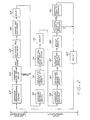
- FIG. 2 A preferred control approach for practicing the present invention is illustrated in Figure 2.
- This control procedure is used in conjunction with the preferred apparatus of Figure 1.
- the procedure is a continuously repeating loop of measurement and adjustment, having two portions.
- the feedforward boiler load signal from the sensor 15 is used to calculate and implement an approximate value for the sulfur trioxide injection flow rate.
- the feedback signals such as the particulate concentration and the electrostatic precipitator power consumption are measured, the sulfur trioxide content and power supply are adjusted responsively, the feedback signals again measured, and the effect of the adjustments assessed.
- the signal of the boiler load sensor 15 is read in a feedforward measurement step 60.
- the signal is ordinarily a time average of values over minutes or hours, with the average value being the one used in the calculations.
- the signal measured in step 60 is compared, numeral 62, with the prior reading of the boiler load sensor 15. If the values are identical within some preselected difference, the next three steps are skipped. If the values are sufficiently different, the sulfur trioxide flow rate is adjusted.
- the approximate required value to attain a preselected resistivity in the particulate matter is estimated, numeral 64.
- the estimation may be performed by any of several distinct techniques.
- the preferred approach is to use stored power plant data for a particular set of operations identical to those in effect, except for a change in fuel flow rate.
- an empirical equation has been developed to permit sulfur trioxide requirements to be estimated from data on the fuel flow and character of the particulate. This or other formulas may be found applicable to particular power plants, as the understanding of plant performance is improved.
- INJ is the estimated sulfur trioxide injection rate in parts per million by volume; K1-K5 and a-e are constants; ACIDB is the sulfur trioxide content in parts per million by volume required to reduce unconditioned fly ash resistivity to the target value, EXP( ) indicates an exponentiation to the base e (i.e., 2.718), LN( ) indicates a logarithm to the base e, ASH is the ash content of the fuel in weight percent, SUL is the sulfur content of the coal in weight percent, BARM is the ash base-to-acid ratio, molecular basis, and SOX is the sulfur trioxide content in parts per million by volume in the gas stream naturally produced by the combustion of the sulfur in the coal.
- the controller 48 Based upon the estimated value, the controller 48 adjusts the sulfur trioxide output of the source 42, numeral 66. There follows a preselected delay 68 to permit the effect of the change in sulfur trioxide injection to propagate through the system and for the system to reach equilibrium under this new operating condition, completing the coarse adjustment.
- the sulfur trioxide injection rate and the duty cycle of the power supply 36 of the electrostatic precipitator 24 are jointly optimized by seeking the optimal performance of the system.
- the result reached by this fine adjustment may confirm the estimate used in the coarse adjustment, but also may be different.
- the coarse adjustment is used to adjust the system to a condition believed to be close to the optimum based upon prior information, but this selection does not constrain the fine adjustment portion of the process from identifying the actual optimum performance condition independent of any empirical estimate.
- the feedback signals are first measured, numeral 70.
- the feedback signals indicated in Figure 1 are the combustion gas particulate concentration sensor 46, the particulate resistivity sensor 37, and the power consumption of the power supply 36.
- Other feedback signals may also be used, as desired, relating to matters such as residual sulfur trioxide content, residual ammonia content, etc., if sensors are provided to measure these quantities.
- the feedback signals are used to calculate a figure of merit, numeral 72. It is not necessarily the case that optimization would be based upon minimizing the value measured by the sensor 46, indicating maximal removal of particulate. This condition might be achieved only at an unacceptably high power consumption, increase in other pollutant levels, or other costs.
- the figure of merit is simply a way of expressing the optimizing factor. For example, the system performance might be optimized by maximizing the quantity (particulate removal)/(power consumption), minimizing the sum of weighted values of particulate content and gaseous pollutant content, or some more complex function.
- the figure of merit is the mathematical expression of the optimizing function, and is selected by the user.
- the system operation is modified in a search procedure designed to locate the optimum system performance as defined by the figure of merit.
- the sulfur trioxide injection rate and the power supply duty cycle are perturbed either separately or simultaneously in a preselected manner, and the resulting change in figure of merit determined. With repetition of this procedure, the operating regime is gradually mapped, to locate the optimum performance as a function of the system variables.
- a “map” is meant a description of the performance of the system as a function of operating variables, either in tabular or mathematical form, and is preferably developed in the microprocessor. Such a map permits optimal performance to be predicted and reached more quickly and with less trial-and-error as more experience and historical data are gained.
- the operating parameters of sulfur trioxide injection rate and duty cycle are first perturbed, numeral 74.
- the perturbation is initially random or based upon some understanding of prior behavior.
- an understanding of the mapping of system performance, as measured by the figure of merit, as a function of sulfur trioxide injection rate and duty cycle is developed.
- Subsequent perturbations are then used to explore unknown regions of the map or move to a known optimum. There are normally relatively few coarse adjustments of the system, with a large number of fine adjustments between coarse adjustments. It is therefore possible to map particular regions to locate optimum performance for a particular power plant output and fuel.
- the preferred mode of adjustment of the electrostatic precipitator duty cycle is illustrated in Figures 3 and 4.
- the power supplied to the electrostatic precipitator 24 by the power supply 48 is preferably rectified, as shown in Figure 3.
- the duty cycle is a full-on condition, so that each rectified half-cycle is delivered to the electrostatic precipitator 24.
- the duty cycle can be modified to remove and eliminate some of the half-cycles.
- two half-cycles are supplied to the electrostatic precipitator 24. There follows a period wherein two consecutive half-cycles are omitted (the omitted half-cycles being indicated in phantom lines in Figure 4).
- the duty cycle of two on and two off repeats indefinitely until modified.
- This intermittent duty cycle takes advantage of the delay time in the formation of a back corona effect, discussed previously.
- the use of an intermittent duty cycle has been known previously, but not in a joint optimization approach.
- the delay 76 may be as much as several hours for a typical large power plant.
- the measurements of the feedback sensors are recorded, numeral 78, and the figure of merit calculated, numeral 80, for the newly perturbed state. These steps are respectively the same as steps 70 and 72 described previously.
- the optimum values are selected and used, numeral 86.
- the system then maintains these values for a period of time, numeral 88, with the system performing optimally. If no optimum has been identified, or upon expiration of the time period 88, or if there is an indication of a change in the feedforward signal, the control process is repeated by proceeding to the measurement of step 60.
Landscapes
- Engineering & Computer Science (AREA)
- Chemical & Material Sciences (AREA)
- Chemical Kinetics & Catalysis (AREA)
- General Chemical & Material Sciences (AREA)
- Automation & Control Theory (AREA)
- Mechanical Engineering (AREA)
- General Engineering & Computer Science (AREA)
- Electrostatic Separation (AREA)
- Other Investigation Or Analysis Of Materials By Electrical Means (AREA)
Applications Claiming Priority (2)
| Application Number | Priority Date | Filing Date | Title |
|---|---|---|---|
| US07/523,312 US4987839A (en) | 1990-05-14 | 1990-05-14 | Removal of particulate matter from combustion gas streams |
| US523312 | 1990-05-14 |
Publications (1)
| Publication Number | Publication Date |
|---|---|
| EP0457224A1 true EP0457224A1 (de) | 1991-11-21 |
Family
ID=24084500
Family Applications (1)
| Application Number | Title | Priority Date | Filing Date |
|---|---|---|---|
| EP91107683A Withdrawn EP0457224A1 (de) | 1990-05-14 | 1991-05-11 | Abscheiden von Teilchen aus Verbrennungsgasströmen |
Country Status (4)
| Country | Link |
|---|---|
| US (1) | US4987839A (de) |
| EP (1) | EP0457224A1 (de) |
| AU (1) | AU652934B2 (de) |
| CA (1) | CA2042507A1 (de) |
Cited By (4)
| Publication number | Priority date | Publication date | Assignee | Title |
|---|---|---|---|---|
| WO1995033568A1 (en) * | 1994-06-07 | 1995-12-14 | The Chemithon Corporation | Flue gas conditioning system for intermittently energized precipitation |
| WO1997006891A1 (de) * | 1995-08-12 | 1997-02-27 | Ing. Walter Hengst Gmbh & Co. Kg | Verfahren zum betreiben eines elektrofilters bzw. einer kurbelgehäuseentlüftung |
| US20100313747A1 (en) * | 2008-01-09 | 2010-12-16 | Karlsson Anders N G | Method and device for controlling an electrostatic precipitator |
| US7857892B2 (en) | 2004-08-11 | 2010-12-28 | Koninklijke Philips Electronics N.V. | Air pollution sensor system |
Families Citing this family (52)
| Publication number | Priority date | Publication date | Assignee | Title |
|---|---|---|---|---|
| US5032154A (en) * | 1989-04-14 | 1991-07-16 | Wilhelm Environmental Technologies, Inc. | Flue gas conditioning system |
| US5282429A (en) * | 1989-08-09 | 1994-02-01 | Chubu Electric Power Company Inc. | Method and system for handling exhaust gas in a boiler |
| US5199363A (en) * | 1989-09-21 | 1993-04-06 | Phoenix Environmental, Ltd. | Method and apparatus for making solid waste material environmentally safe using heat |
| US5196038A (en) * | 1990-03-15 | 1993-03-23 | Wright Robert A | Flue gas conditioning system |
| US5350441A (en) * | 1990-03-15 | 1994-09-27 | Wilhelm Environmental Technologies, Inc. | Flue gas conditioning system |
| US5122162A (en) * | 1990-03-19 | 1992-06-16 | Wahlco, Inc. | Control system for flue gas conditioning |
| US5074226A (en) * | 1991-02-15 | 1991-12-24 | Field Service Associates, Inc. | Flue gas conditioning system |
| US5229077A (en) * | 1991-08-16 | 1993-07-20 | Environmental Elements Corp. | Sulfur rate control system |
| US5356597A (en) * | 1992-04-07 | 1994-10-18 | Wilhelm Environmental Technologies, Inc. | In-duct flue gas conditioning system |
| US5240470A (en) * | 1992-04-07 | 1993-08-31 | Wilhelm Environmental Technologies, Inc. | In-duct flue gas conditioning system |
| US5288303A (en) * | 1992-04-07 | 1994-02-22 | Wilhelm Environmental Technologies, Inc. | Flue gas conditioning system |
| GB2297925B (en) * | 1992-04-07 | 1996-10-16 | Wilhelm Env Tech Inc | Flue gas conditioning system |
| WO1993019852A1 (en) * | 1992-04-07 | 1993-10-14 | Wilhelm Environmental Technologies, Inc. | Flue gas conditioning system |
| SE501119C2 (sv) * | 1993-03-01 | 1994-11-21 | Flaekt Ab | Sätt att styra tillförsel av konditioneringsmedel till en elektrostatisk stoftavskiljare |
| US5370720A (en) * | 1993-07-23 | 1994-12-06 | Welhelm Environmental Technologies, Inc. | Flue gas conditioning system |
| US5665142A (en) * | 1994-04-12 | 1997-09-09 | Wilhelm Environmental Technologies, Inc. | Flue gas conditioning system and method using native SO2 feedstock |
| EP0712477A1 (de) * | 1994-06-15 | 1996-05-22 | Thermal Energy Systems, Incorporated | Vorrichtung und verfahren zur reduzierung der feststoffemissionen bei verbrennungsprozessen |
| US5538539A (en) * | 1995-01-20 | 1996-07-23 | Wahlco, Inc. | Catalytic sulfur trioxide flue gas conditioning |
| US5688308A (en) * | 1995-05-30 | 1997-11-18 | Trion, Inc. | Electrostatic air cleaning system with air flow sensor |
| US6152053A (en) * | 1999-07-30 | 2000-11-28 | Abb Alstom Power Inc. | Method and assembly for converting waste water accumulated in a fossil fuel-fired power generation system |
| US8079845B2 (en) * | 2005-05-10 | 2011-12-20 | Environmental Energy Services, Inc. | Processes for operating a utility boiler and methods therefor |
| US7465338B2 (en) | 2005-07-28 | 2008-12-16 | Kurasek Christian F | Electrostatic air-purifying window screen |
| US7531154B2 (en) * | 2005-08-18 | 2009-05-12 | Solvay Chemicals | Method of removing sulfur dioxide from a flue gas stream |
| US7481987B2 (en) * | 2005-09-15 | 2009-01-27 | Solvay Chemicals | Method of removing sulfur trioxide from a flue gas stream |
| US8656846B2 (en) * | 2006-05-01 | 2014-02-25 | Energy Technologies, Inc. | Continuous real time heating value (BTU)/coal flow balancing meter |
| KR100856873B1 (ko) * | 2007-01-05 | 2008-09-04 | 연세대학교 산학협력단 | 무전해도금용 촉매활성 방법 |
| US8955763B2 (en) * | 2007-10-04 | 2015-02-17 | Consolidated Edison Company Of New York, Inc. | Building heating system and method of operation |
| US8851882B2 (en) * | 2009-04-03 | 2014-10-07 | Clearsign Combustion Corporation | System and apparatus for applying an electric field to a combustion volume |
| KR20120129907A (ko) * | 2010-01-13 | 2012-11-28 | 클리어사인 컨버스천 코포레이션 | 열 전달의 전기적 제어 방법 및 장치 |
| PL2354651T3 (pl) * | 2010-01-18 | 2014-11-28 | General Electric Technology Gmbh | System odzysku ciepła spalin w połączeniu z poprawą odpylania jako rozwiązanie w modernizacji istniejących elektrowni węglowych |
| US11073280B2 (en) | 2010-04-01 | 2021-07-27 | Clearsign Technologies Corporation | Electrodynamic control in a burner system |
| US8398744B2 (en) * | 2010-09-21 | 2013-03-19 | General Electric Company | Method and apparatus for air pollution control |
| US8663362B2 (en) | 2011-02-11 | 2014-03-04 | Trane International Inc. | Air cleaning systems and methods |
| US9284886B2 (en) | 2011-12-30 | 2016-03-15 | Clearsign Combustion Corporation | Gas turbine with Coulombic thermal protection |
| MX2014007905A (es) | 2011-12-30 | 2015-04-16 | Clearsign Comb Corp | Metodo y aparato para la mejora de la radiacion de la llama. |
| CN104169725B (zh) | 2012-03-01 | 2018-04-17 | 克利尔赛恩燃烧公司 | 配置为与火焰电动交互的惰性电极和系统 |
| US9377195B2 (en) | 2012-03-01 | 2016-06-28 | Clearsign Combustion Corporation | Inertial electrode and system configured for electrodynamic interaction with a voltage-biased flame |
| US9289780B2 (en) | 2012-03-27 | 2016-03-22 | Clearsign Combustion Corporation | Electrically-driven particulate agglomeration in a combustion system |
| US9366427B2 (en) | 2012-03-27 | 2016-06-14 | Clearsign Combustion Corporation | Solid fuel burner with electrodynamic homogenization |
| WO2013147956A1 (en) | 2012-03-27 | 2013-10-03 | Clearsign Combustion Corporation | Multiple fuel combustion system and method |
| AU2013245311B2 (en) | 2012-04-04 | 2015-11-12 | General Electric Technology Gmbh | Flue gas conditioning system and method |
| EP2856031B1 (de) | 2012-05-31 | 2016-10-19 | Clearsign Combustion Corporation | Brenner mit niedrigem nox-ausstoss und betriebsverfahren für den brenner mit niedrigem nox-ausstoss |
| US10018356B2 (en) * | 2012-07-12 | 2018-07-10 | The Babcock & Wilcox Company | System and method for controlling one or more process parameters associated with a combustion process |
| US9702550B2 (en) | 2012-07-24 | 2017-07-11 | Clearsign Combustion Corporation | Electrically stabilized burner |
| US9310077B2 (en) | 2012-07-31 | 2016-04-12 | Clearsign Combustion Corporation | Acoustic control of an electrodynamic combustion system |
| US8911699B2 (en) | 2012-08-14 | 2014-12-16 | Clearsign Combustion Corporation | Charge-induced selective reduction of nitrogen |
| US9513006B2 (en) | 2012-11-27 | 2016-12-06 | Clearsign Combustion Corporation | Electrodynamic burner with a flame ionizer |
| WO2014085720A1 (en) | 2012-11-27 | 2014-06-05 | Clearsign Combustion Corporation | Multijet burner with charge interaction |
| US20140162198A1 (en) | 2012-11-27 | 2014-06-12 | Clearsign Combustion Corporation | Multistage ionizer for a combustion system |
| US9562681B2 (en) | 2012-12-11 | 2017-02-07 | Clearsign Combustion Corporation | Burner having a cast dielectric electrode holder |
| US9441834B2 (en) | 2012-12-28 | 2016-09-13 | Clearsign Combustion Corporation | Wirelessly powered electrodynamic combustion control system |
| US10429297B2 (en) * | 2017-01-26 | 2019-10-01 | Acumentor Llc | Monitoring opacity of smoke exhausted by wood stove and controlling wood stove based on same |
Citations (4)
| Publication number | Priority date | Publication date | Assignee | Title |
|---|---|---|---|---|
| FR2329353A1 (fr) * | 1975-11-03 | 1977-05-27 | Efremidi Anatoly | Installation de precipitation electrostatique, notamment pour le depoussierage des gaz |
| FR2503583A1 (fr) * | 1981-04-09 | 1982-10-15 | Mitsubishi Heavy Ind Ltd | Procede et appareil pour la capture electrique de poussieres |
| DE3430016A1 (de) * | 1984-08-16 | 1986-03-20 | Metallgesellschaft Ag, 6000 Frankfurt | Optimierung der Rauchgaskonditionierung |
| EP0274132A2 (de) * | 1987-01-06 | 1988-07-13 | The Chemithon Corporation | S03-Konditionierungssystem für Abgase |
Family Cites Families (3)
| Publication number | Priority date | Publication date | Assignee | Title |
|---|---|---|---|---|
| SE430472B (sv) * | 1982-03-25 | 1983-11-21 | Flaekt Ab | Anordning for att i en elektrofilteranleggning med ett flertal elektrodgrupper mojliggora en reglering av strom- och/eller spenningsverdena anslutna till resp elektrodgrupp sa att totala energibehovet kan minimeras mot. |
| US4885139A (en) * | 1985-08-22 | 1989-12-05 | The United States Of America As Represented By The Administrator Of U.S. Environmental Protection Agency | Combined electrostatic precipitator and acidic gas removal system |
| US4793268A (en) * | 1987-11-27 | 1988-12-27 | Apollo Technologies Int'l | Method for controlling additive feed in a boiler system |
-
1990
- 1990-05-14 US US07/523,312 patent/US4987839A/en not_active Expired - Fee Related
-
1991
- 1991-05-11 EP EP91107683A patent/EP0457224A1/de not_active Withdrawn
- 1991-05-14 AU AU77048/91A patent/AU652934B2/en not_active Ceased
- 1991-05-14 CA CA002042507A patent/CA2042507A1/en not_active Abandoned
Patent Citations (4)
| Publication number | Priority date | Publication date | Assignee | Title |
|---|---|---|---|---|
| FR2329353A1 (fr) * | 1975-11-03 | 1977-05-27 | Efremidi Anatoly | Installation de precipitation electrostatique, notamment pour le depoussierage des gaz |
| FR2503583A1 (fr) * | 1981-04-09 | 1982-10-15 | Mitsubishi Heavy Ind Ltd | Procede et appareil pour la capture electrique de poussieres |
| DE3430016A1 (de) * | 1984-08-16 | 1986-03-20 | Metallgesellschaft Ag, 6000 Frankfurt | Optimierung der Rauchgaskonditionierung |
| EP0274132A2 (de) * | 1987-01-06 | 1988-07-13 | The Chemithon Corporation | S03-Konditionierungssystem für Abgase |
Cited By (7)
| Publication number | Priority date | Publication date | Assignee | Title |
|---|---|---|---|---|
| WO1995033568A1 (en) * | 1994-06-07 | 1995-12-14 | The Chemithon Corporation | Flue gas conditioning system for intermittently energized precipitation |
| WO1997006891A1 (de) * | 1995-08-12 | 1997-02-27 | Ing. Walter Hengst Gmbh & Co. Kg | Verfahren zum betreiben eines elektrofilters bzw. einer kurbelgehäuseentlüftung |
| DE19680694C1 (de) * | 1995-08-12 | 1999-03-25 | Hengst Walter Gmbh & Co Kg | Verfahren zur Kurbelgehäuseentlüftung für eine Brennkraftmaschine |
| US5911213A (en) * | 1995-08-12 | 1999-06-15 | Firma Ing. Walter Hengst Gmbh & Co. Kg | Process for operating an electric filter for a crankcase ventilator |
| US7857892B2 (en) | 2004-08-11 | 2010-12-28 | Koninklijke Philips Electronics N.V. | Air pollution sensor system |
| US20100313747A1 (en) * | 2008-01-09 | 2010-12-16 | Karlsson Anders N G | Method and device for controlling an electrostatic precipitator |
| US8414680B2 (en) * | 2008-01-09 | 2013-04-09 | Alstom Technology Ltd | Method and device for controlling an electrostatic precipitator |
Also Published As
| Publication number | Publication date |
|---|---|
| US4987839A (en) | 1991-01-29 |
| AU652934B2 (en) | 1994-09-15 |
| CA2042507A1 (en) | 1991-11-15 |
| AU7704891A (en) | 1991-11-14 |
Similar Documents
| Publication | Publication Date | Title |
|---|---|---|
| US4987839A (en) | Removal of particulate matter from combustion gas streams | |
| EP0457225B1 (de) | Regelung der Zugabe von Konditionierungsmitteln in Abgasen | |
| US5032154A (en) | Flue gas conditioning system | |
| US5288309A (en) | Flue gas conditioning agent demand control apparatus | |
| US7081152B2 (en) | ESP performance optimization control | |
| EP0274132B1 (de) | S03-Konditionierungssystem für Abgase | |
| WO2007070220A2 (en) | Model based control and estimation of mercury emissions | |
| US5567226A (en) | Apparatus and method for enhancing the performance of a particulate collection device | |
| AU2008346572B2 (en) | Method and device for controlling an electrostatic precipitator | |
| WO1995033568A1 (en) | Flue gas conditioning system for intermittently energized precipitation | |
| Navarrete et al. | Influence of plate spacing and ash resistivity on the efficiency of electrostatic precipitators | |
| Bäck | Enhancing ESP efficiency for high resistivity fly ash by reducing the flue gas temperature | |
| US5122162A (en) | Control system for flue gas conditioning | |
| Dismukes | Conditioning of fly ash with ammonia | |
| US7226570B2 (en) | Fly ash conditioning systems | |
| JPS5936559A (ja) | 電気集塵機の制御方法 | |
| Baxter | Recent electrostatic precipitator experience with ammonia conditioning of power boiler flue gases | |
| RU2699373C1 (ru) | Способ регенерации электродов электрофильтра и устройство для его осуществления | |
| JP3731471B2 (ja) | 高イオウ油焚きボイラの排煙処理方法 | |
| Krigmont et al. | Development of the Intelligent Flue Gas Conditioning Injection Rate Control | |
| Petersen | Performance of electrostatic precipitators | |
| JP2679558B2 (ja) | 焼結機主排ガス用電気集塵機の運転方法 | |
| Bulley | USA trends in power station emission control | |
| Plaks | Fabric filtration with integral particle charging and collection in a combined electric and flow field: Part II. Development and verification of the mathematical engineering design model | |
| Parker | The precipitation of difficult dust |
Legal Events
| Date | Code | Title | Description |
|---|---|---|---|
| PUAI | Public reference made under article 153(3) epc to a published international application that has entered the european phase |
Free format text: ORIGINAL CODE: 0009012 |
|
| AK | Designated contracting states |
Kind code of ref document: A1 Designated state(s): AT BE CH DE DK ES FR GB GR IT LI LU NL SE |
|
| 17P | Request for examination filed |
Effective date: 19920425 |
|
| 17Q | First examination report despatched |
Effective date: 19940414 |
|
| STAA | Information on the status of an ep patent application or granted ep patent |
Free format text: STATUS: THE APPLICATION IS DEEMED TO BE WITHDRAWN |
|
| 18D | Application deemed to be withdrawn |
Effective date: 19950617 |