EP0457285B1 - Appareil pour la génération du champ magnétique statique d'un système à IRM et méthode pour l'assemblage du dit appareil - Google Patents
Appareil pour la génération du champ magnétique statique d'un système à IRM et méthode pour l'assemblage du dit appareil Download PDFInfo
- Publication number
- EP0457285B1 EP0457285B1 EP19910107809 EP91107809A EP0457285B1 EP 0457285 B1 EP0457285 B1 EP 0457285B1 EP 19910107809 EP19910107809 EP 19910107809 EP 91107809 A EP91107809 A EP 91107809A EP 0457285 B1 EP0457285 B1 EP 0457285B1
- Authority
- EP
- European Patent Office
- Prior art keywords
- magnet
- shield body
- cylindrical
- magnetic shield
- magnetic field
- Prior art date
- Legal status (The legal status is an assumption and is not a legal conclusion. Google has not performed a legal analysis and makes no representation as to the accuracy of the status listed.)
- Expired - Lifetime
Links
- 230000005291 magnetic effect Effects 0.000 title claims description 156
- 230000003068 static effect Effects 0.000 title claims description 48
- 238000000034 method Methods 0.000 title claims description 10
- 238000002595 magnetic resonance imaging Methods 0.000 claims description 13
- 230000007246 mechanism Effects 0.000 claims description 11
- 230000005389 magnetism Effects 0.000 claims description 4
- 238000001816 cooling Methods 0.000 claims 2
- 230000004907 flux Effects 0.000 description 9
- 238000009434 installation Methods 0.000 description 7
- 230000000694 effects Effects 0.000 description 6
- 230000007423 decrease Effects 0.000 description 4
- 230000003247 decreasing effect Effects 0.000 description 4
- 239000002826 coolant Substances 0.000 description 3
- 230000008878 coupling Effects 0.000 description 3
- 238000010168 coupling process Methods 0.000 description 3
- 238000005859 coupling reaction Methods 0.000 description 3
- 125000006850 spacer group Chemical group 0.000 description 3
- 238000005481 NMR spectroscopy Methods 0.000 description 2
- 230000002411 adverse Effects 0.000 description 2
- 239000000696 magnetic material Substances 0.000 description 2
- 238000004519 manufacturing process Methods 0.000 description 2
- 230000000593 degrading effect Effects 0.000 description 1
- 230000005294 ferromagnetic effect Effects 0.000 description 1
- 229910052734 helium Inorganic materials 0.000 description 1
- 239000001307 helium Substances 0.000 description 1
- SWQJXJOGLNCZEY-UHFFFAOYSA-N helium atom Chemical compound [He] SWQJXJOGLNCZEY-UHFFFAOYSA-N 0.000 description 1
- 239000012212 insulator Substances 0.000 description 1
- 239000007788 liquid Substances 0.000 description 1
- 238000003325 tomography Methods 0.000 description 1
Images


Classifications
-
- G—PHYSICS
- G01—MEASURING; TESTING
- G01R—MEASURING ELECTRIC VARIABLES; MEASURING MAGNETIC VARIABLES
- G01R33/00—Arrangements or instruments for measuring magnetic variables
- G01R33/20—Arrangements or instruments for measuring magnetic variables involving magnetic resonance
- G01R33/28—Details of apparatus provided for in groups G01R33/44 - G01R33/64
- G01R33/38—Systems for generation, homogenisation or stabilisation of the main or gradient magnetic field
- G01R33/381—Systems for generation, homogenisation or stabilisation of the main or gradient magnetic field using electromagnets
- G01R33/3815—Systems for generation, homogenisation or stabilisation of the main or gradient magnetic field using electromagnets with superconducting coils, e.g. power supply therefor
-
- G—PHYSICS
- G01—MEASURING; TESTING
- G01R—MEASURING ELECTRIC VARIABLES; MEASURING MAGNETIC VARIABLES
- G01R33/00—Arrangements or instruments for measuring magnetic variables
- G01R33/20—Arrangements or instruments for measuring magnetic variables involving magnetic resonance
- G01R33/28—Details of apparatus provided for in groups G01R33/44 - G01R33/64
- G01R33/42—Screening
- G01R33/421—Screening of main or gradient magnetic field
Definitions
- the present invention relates to an apparatus for generating a static magnetic field used by an MRI (Magnetic Resonance Imaging) system that obtains at least one of anatomical data and organic data of a living body by utilizing a magnetic resonance phenomenon, and a method for assembling the apparatus.
- MRI Magnetic Resonance Imaging
- An MRI system uses a static magnetic field generating apparatus capable of generating a high-strength, high-uniformity static magnetic field in order to obtain high-precision vital data.
- a static field generating apparatus has a magnet for generating a high-strength magnetic field of several thousands gauss or more.
- a magnet that generates such a high-strength magnetic field has electromagnetic adverse effects on other electronic appliances arranged close to it.
- the static magnetic field generating apparatus has a magnetic shield body for decreasing a leakage magnetic field generated by the magnet. The magnetic shield body reduces the space required for installing an MRI system. This moderates the installation condition for the MRI system.
- Document EP-A-0 243 669 discloses a (NMR) tomographic apparatus comprising a magnet system with magnetic coils which are supported by a frame structure through supporting elements. The magnet system is surrounded by shielding elements. At the frame structure adjusting means are provided for adjusting the respective magnetic coils.
- Document WO-A-89/01636 describes a unitary superconducting electromagnet having an outer ferromagnetic body about an inner generally cylindrical body containing the coils and used for a nuclear magnetic resonance tomography apparatus.
- the electromagnet has adjusting blocks secured to the cylindrical inner body for movement of this body vertically and longitudinally in the outer body for precise positioning.
- Document EP-A-0 141 149 discloses a magnetic apparatus wherein four bar-like shielding elements surround the surface of several cylindrical coils. In the apparatus the magnetic coils can be adjusted.
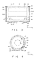
- a conventional static magnetic field generating apparatus having a magnet and a magnetic shield body will be described with reference to Figs. 1 and 2.
- a static magnetic field generating apparatus is constituted by a magnet 100, e.g., a superconducting magnet, and a magnetic shield body 120 enclosing the magnet 100.
- the magnet 100 is cylindrical.
- An object to be examined (not shown) is placed in a hollow portion 102 inside the magnet 100.
- Magnet legs 104 for supporting the magnet 100 are fixed at four lower corners of the magnet 100.
- the magnetic shield body 120 consists of a plurality of square rods 122, two terminal lids 124 each having a central opening 124A, and a plurality of bolts 126 for fixing the square rods 122 to the terminal lids 124.
- the plurality of square rods 122, the two terminal lids 124, and the plurality of bolts 126 are made of a magnetic material.
- the plurality of square rods 122 are arranged on the outer circumferential surfaces of the terminal lids 124.
- the square rods 122 are fixed on the terminal lids 124 by the bolts 126.
- Shield legs 128 are fixed on the four lower corners of the magnetic shield body 120.
- the magnet legs 104 supporting the magnet 100 penetrate the square rods 122 constituting the magnetic shield body 120. Thus, four magnet leg accesses 130 are formed in advance in the magnetic shield body 120.
- the magnet legs 104 supporting the magnet 100 penetrate the square rods 122 constituting the magnetic shield body 120. Therefore, the four magnet leg accesses 130 are formed in advance in the magnetic shield body 120. Accordingly, the square rods 122 are not present where the magnet leg accesses 130 are present.
- the square rods 122 are the magnetic flux paths (magnetic paths). Therefore, the partial absence of the square rods 122 interferes with flow of the magnetic fluxes within the magnetic shield body 120. As a result, the static magnetic field distribution of the hollow portion 102 of the magnet 100 is disturbed, thus degrading the uniformity in static magnetic field. High-precision vital data cannot be obtained due to this. In addition, the leakage magnetic flux amount is increased, and the shield effect is degraded. This imposes a strict condition for installation of the MRI system.
- Document GB-A-2 197 487 discloses a magnetic shield for a magnetic resonance magnet adapted to surround the magnetic resonance magnet.
- the shield comprises two units which are so constructed that they can be assembled to surround the magnet by moving them horizontally.
- the magnetic shield body has a plurality of legs attached to the underside of the outer surface thereof and a plurality of support members for supporting a cylindrical superconducting magnet.
- the shield body has two axial openings, two terminal lids with a central opening, which are butted against the two axial openings, and a plurality of bolts for fixing the terminal lids to the cylindrical shell.
- a magnetic shield body is shown which is split into two halves along a direction parallel to a longitudinal direction of the cylindrical magnet.
- the static magnet of this apparatus is fixed on the outer wall of the cylindrical magnetic shield, and thus the magnetic shield is provided with cut-away portions or openings into which the supporting legs of the static magnet are inserted.
- the size of the cut-away portions or openings may effect the precision of the uniform magnetic field and the image processing.
- an object of the present invention to provide an apparatus for generating a static magnetic field, which is used in an MRI system capable of obtaining high-precision vital data and which can moderate an installation condition for the MRI system, and a method for assembling the apparatus.
- an apparatus for generating a static magnetic field used by a magnetic resonance imaging system comprising a cylindrical superconducting magnet for generating a static magnetic field, a magnetic shield body for shielding magnetism generated by the cylindrical superconducting magnet, the magnetic shield body having a plurality of legs attached at predetermined positions to the underside of the outer surface thereof and being coaxially arranged outside of the cylindrical superconducting magnet, and a plurality of support members for supporting the cylindrical superconducting magnet, wherein said support members are fixed to the inner surface of said magnetic shield body at positions corresponding to the positions of said plurality of legs, said support members each have a mechanism for performing position adjustment of said magnetic shield body and said cylindrical superconducting magnet in x-, y- and z-axis directions, and said magnet shield body includes a cylindrical shell having two axial openings which comprises first and second split bodies split into halves along a direction parallel to a longitudinal direction of said cylindrical magnet, two terminal lids each having a central opening which are butted against the two
- This object is also achieved with a method for assembling an apparatus for generating a static magnetic field used by a magnetic resonance imaging system, said apparatus comprising a cylindrical magnet for generating a static magnetic field in a predetermined magnetic field generation direction, a magnetic shield body for shielding magnetism generated by said cylindrical magnet, said magnetic shield body having a plurality of legs at lower portions of an outer surface thereof, and being coaxially arranged outside of said cylindrical magnet, said magnetic shield body includes a cylindrical shell having two axial openings which comprises first and second split bodies split into halves along a direction parallel to a longitudinal direction of said cylindrical magnet, two terminal lids each having a central opening which are butted against the two axial openings of the cylindrical shell, and a plurality of bolts for fixing the terminal lids to the cylindrical shell, and a plurality of support members being fixed to the inner surface of said magnetic shield body at positions corresponding to the positions of said plurality of legs, for supporting said cylindrical magnet, said support members being fixed to those lower portions of an inner surface of said magnetic shield body which correspond to positions
- the magnetic shield body of this static magnetic field generating apparatus has no magnet leg accesses, the magnetic shield effect and the magnetic field uniformity are improved.
- the magnetic shield body is split into at least halves in a direction perpendicular to the magnetic field generating direction, assembly of the apparatus is easy.
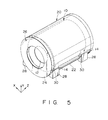
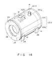
- a static magnetic field generating apparatus comprises a cylindrical superconducting magnet 10 and a magnetic shield body 20 enclosing the superconducting magnet 10. More specifically, the superconducting magnet 10 is arranged substantially coaxially in the magnetic shield body 20. The magnetic shield body 20 decreases the leakage magnetic flux amount of the magnetic field generated by the superconducting magnet 10.
- a superconducting coil, a coolant such as liquid helium, and a heat insulator are sealed in the cylindrical superconducting magnet 10.
- a high-strength, high-uniformity static magnetic field can be generated in a hollow portion 12 in the superconducting magnet 10.
- An object to be examined (not shown) can be placed in the hollow portion 12 of the superconducting magnet 10. Therefore, a high-strength, high-uniformity static magnetic field can be applied to the object (not shown).
- a gradient magnetic field and an RF magnetic field are required in order to acquire a magnetic resonance signal from a specific portion of the object.
- a coil for generating the gradient magnetic field and a coil for generating the RF magnetic field can be arranged in the hollow portion 12 in the cylindrical superconducting magnet 10. These coils are not shown in the drawings.
- the coil for acquiring the magnetic resonance signal also serves as the coil for generating the RF magnetic field. However, an independent coil for acquiring the magnetic resonance signal can be used instead.
- Magnet support members 14 for supporting the superconducting magnet 10 are fixed on the four lower corners of its outer circumferential surface.
- the magnet shield body 20 consists of a cylindrical shell 22, two terminal lids 24 each having a central opening 24A, and a plurality of bolts 26 for fixing the terminal lids 24 to the cylindrical shell 22.
- the shell 22, the two terminal lids 24, and the plurality of bolts 26 are made of a magnetic material.
- the terminal lids 24 are butted against the two axial openings of the cylindrical shell 22.
- the two terminal lids 24 are fixed to the cylindrical shell 22 by the bolts 26.
- Shield body legs 28 are fixed on the four lower corners of the magnetic shield body 20.
- Support members 30 for receiving the support members 14 of the magnet 10 are fixed on the four lower corners of the inner circumferential surface of the magnetic shield body 20.
- Each support member 30 includes a position adjusting mechanism 40.
- Each position adjusting mechanism 40 can move in at least one of x-, y-, and z-axis directions.
- the cylindrical superconducting magnet 10 can be set at a desired position.
- the four magnet support members 14 are supported by the four support members 30 of the magnetic shield body 20.
- each position adjusting mechanism 40 comprises bolts 41, 42, 43, and 45 screwed to the corresponding support member 30, and a spacer 44.
- the bolt 41 adjusts the position of the cylindrical superconducting magnet 10 in the vertical direction (y-axis direction).
- the bolts 42 and 43 adjust the position of the superconducting magnet 10 in the horizontal direction (x-axis direction).
- the spacer 44 is arranged between the support member 30 and the magnet support member 14.
- the bolts 45 serve to fix the support member 30 and the magnet support member 14.
- the position adjusting mechanism 40 having this arrangement, when the bolt 45 is unscrewed and the bolts 41, 42, and 43 and the spacer 44 are adjusted, the positional relationship between the cylindrical superconducting magnet 10 and cylindrical shell 22 of the magnetic shield body 20 can be optimized.
- the magnetic shield body 20 is free from a notch, a hole, or the like that interferes with the magnetic flux flow.
- the magnetic fluxes generated by the cylindrical superconducting magnet 10 flow in the magnetic shield body 20 in an ideal manner.
- the magnetic shield effect is improved and the magnetic field uniformity becomes good.
- the magnetic shield body 20 employs the cylindrical shell 22
- the shell 22 and the terminal lids 24 can be coupled to each other easily and reliably. In this case, only several bolts 26 are required to couple the cylindrical shell 22 and the terminal lids 24.
- cylindrical superconducting magnet 10 and the magnetic shield body 20 are integrally formed, they need not be disassembled for transportation. Also, they need not be reassembled for installation, resulting in easy installation.
- the structure becomes simple to decrease the manufacturing cost, the assembly cost, and the installation cost, resulting in an inexpensive apparatus.
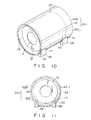
- a cylindrical superconducting magnet 10 is substantially the same as that of the first embodiment. No terminal lids are provided, and a magnetic shield body comprising a split type cylindrical shell 22-1 split into halves is employed. Since the split type cylindrical shell 22-1 does not have terminal lids, the cylindrical superconducting magnet 10 preferably has an auto shield function.
- the cylindrical superconducting magnet 10 having the auto shield function has a coil assembly in which a cancel coil is provided outside a main coil.
- the split type cylindrical shell 22-1 consists of lower and upper split bodies 22A and 22B. The lower and upper split bodies 22A and 22B are coupled through split lines 32. The split lines 32 are of a surface coupling type.
- a static magnetic field generating apparatus 20-1 according to the third embodiment does not have terminal lids and adopts a magnetic shield body comprising a split type cylindrical body 22-1 split into halves, as in the second embodiment.
- Lower and upper split bodies 22A and 22B are coupled through split lines 34.
- the split lines 34 are of a step coupling type.
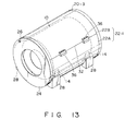
- a static magnetic field generating apparatus 20-2 according to the fourth embodiment employs a magnetic shield body 22-2 obtained by providing terminal lids 24 to a split type cylindrical shell 22-1, unlike in the second and third embodiments.
- a static magnetic field generating apparatus 20-3 of the fifth embodiment is substantially the same as that of the fourth embodiment except that in the fifth embodiment flange mechanisms 36 are provided to split lines 32 for fixing and coupling lower and upper split bodies 22A and 22B.
- a static magnetic field generating apparatus 20-4 of the sixth embodiment is substantially the same as that of the fourth embodiment except for the following respects. Namely, in the sixth embodiment, a notch 22cl for a coolant supply port 16 and a notch 22c2 for a charging port 18 are formed in an upper split body 22C so as to allow mounting of the coolant supply port 16 and the charging port 18.
- step S1 the lower magnetic shield body 22A is installed on a floor (not shown).
- step S2 the magnet 10 is suspended and is moved downward to the interior of the lower split body 22A such that the support members 14 of the magnet 10 are received by the support members 30 of the lower split body 22A.
- step S2 the upper split body 22B is placed on the lower split body 22A.
- step S3 the terminal lids 24 are butted against the openings of the cylindrical shell 22-1 and screwed to it by the bolts 26.
- the magnet 10 is a superconducting magnet. However, it can be a normal conductive magnet.
- the support members 30 are provided on the inner circumferential surface of the cylindrical shell 22 and the magnet 10 is received by and fixed on the support members 30.
- the number of notches or holes in the magnetic shield body 20 is decreased, resulting in an improvement in magnetic field uniformity and decrease in leakage magnetic field. Since the magnet 10 and the magnetic shield body 20 are integrally formed, disassembly and assembly for installation can be easily performed.
- the terminal lids and the cylindrical shell can be coupled easily and reliably, a variation in magnetic field uniformity due to assembly is decreased, thus providing an inexpensive magnetic shield body having a stable quality.
Landscapes
- Physics & Mathematics (AREA)
- Condensed Matter Physics & Semiconductors (AREA)
- General Physics & Mathematics (AREA)
- Health & Medical Sciences (AREA)
- Epidemiology (AREA)
- Electromagnetism (AREA)
- Magnetic Resonance Imaging Apparatus (AREA)
- Shielding Devices Or Components To Electric Or Magnetic Fields (AREA)
Claims (3)
- Appareil pour créer un champ magnétique statique pour un système d'imagerie à résonance magnétique, comprenant :caractérisé en ce queun aimant (10) supraconducteur cylindrique pour créer un champ magnétique statique ;un corps formant écran magnétique (20, 20-1, 20-2, 20-3, 20-4) pour faire écran au magnétisme créé par ledit aimant (10) supraconducteur cylindrique, ledit corps formant écran magnétique (20, 22A, 22B, 24, 24A, 26) ayant plusieurs pieds (28) fixés à des emplacements prédéterminés à la face de dessous de sa surface extérieure en disposition coaxiale à l'extérieur dudit aimant (10) supraconducteur cylindrique ; etdes éléments supports (30) pour supporter ledit aimant (10) supraconducteur cylindrique,lesdits éléments supports (30) sont fixés à la surface intérieure dudit corps formant écran magnétique (20, 22A, 22B, 24, 24A, 26) à des emplacements correspondant aux emplacements desdits pieds (28),lesdits éléments supports (30) ont chacun un mécanisme (40) pour effectuer un réglage de position dudit corps formant écran magnétique (20, 22A, 22B, 24, 24A, 26) et dudit aimant (10) supraconducteur magnétique dans des directions d'axes x, y et z, etledit corps formant aimant magnétique (20, 22A, 22B, 24, 24A, 26) comprend une enveloppe cylindrique (22) ayant deux ouvertures axiales qui comprend des premier et deuxième corps fractionnés (22A, 22B) fractionnés en moitiés le long d'une direction parallèle à une direction longitudinale dudit aimant (10) cylindrique, deux couvercles (24) terminaux ayant chacun une ouverture centrale (24A) qui sont aboutés contre les deux ouvertures axiales de l'enveloppe cylindrique (22), et des vis (26) pour fixer les couvercles terminaux (24) à l'enveloppe cylindrique (22).
- Appareil pour système d'imagerie à résonance magnétique selon la revendication 1, dans lequel ledit corps formant écran magnétique (20, 22A, 22B, 24, 24A, 26) a une encoche (20C1-20C2) dans une partie supérieure pour permettre à un élément (16, 18) de refroidissement et de chargement de s'y étendre, ledit élément (16, 18) de refroidissement et de chargement étant disposé sur ledit aimant (10) cylindrique.
- Procédé pour assembler un appareil pour créer un champ magnétique statique pour un système d'imagerie à résonance magnétique, ledit appareil comprenant :un aimant (10) cylindrique pour créer un champ magnétique statique dans une direction de création de champ magnétique prédéterminée ;un corps formant écran magnétique (20, 22A, 22B, 24, 24A, 26) pour confirmer le magnétisme créé par ledit aimant (10) cylindrique, ledit corps formant écran magnétique (20, 22A, 22B, 24, 24A, 26) ayant des pieds (28) à des parties inférieures de sa surface extérieure, coaxialement à l'extérieur dudit aimant (10) cylindrique, ledit corps formant écran magnétique (20, 22A, 22B, 24, 24A, 26) comporte une enveloppe cylindrique (22) ayant deux ouvertures axiales comprenant des premier et deuxième corps fractionnés (22A, 22B) fractionnés en moitiés le long d'une direction parallèle à une direction longitudinale dudit aimant (10) cylindrique, deux couvercles (24) terminaux ayant chacun une ouverture centrale (24A) qui sont aboutés contre les deux ouvertures axiales de l'enveloppe cylindrique (22), et des vis (26) pour fixer les couvercles terminaux (24) à l'enveloppe cylindrique (22) ; etdes éléments supports (30) fixés à la surface intérieure dudit corps formant écran magnétique (20, 22A, 22B, 24, 24A, 26) a des emplacements correspondant aux emplacements desdits pieds (28), pour supporter ledit aimant (10) cylindrique, lesdits éléments supports (30) étant fixés aux parties inférieures d'une surface intérieure dudit corps formant écran magnétique (20, 22A, 22B, 24, 24A, 26) qui correspondent aux emplacements desdits pieds (28), et chacun ayant un mécanisme (40) pour effectuer un réglage de position dudit corps formant écran magnétique (20, 22A, 22B, 24, 24A, 26) et dudit aimant (10) cylindrique dans des directions d'axes x, y et z, ledit procédé comprenant :une première étape d'installation dudit premier corps fractionné (20A) dudit corps formant écran magnétique (20 , 22A, 22B, 24, 24A, 26) sur un sol ;une deuxième étape de supportage dudit aimant (10) cylindrique par lesdits éléments supports (30) en suspendant et déplaçant ledit aimant (10) cylindrique vers le bas à l'intérieur dudit premier corps fractionné (22A);une troisième étape de placement dudit deuxième corps fractionné (22B) dudit corps formant écran magnétique (20, 22A, 22B, 24, 24A, 26) sur ledit premier corps fractionné (22A);une quatrième étape d'aboutement contre les deux ouvertures axiales de l'enveloppe cylindrique (22) desdits deux couvercles (24) terminaux et ; une cinquième étape de fixation des couvercles (24) terminaux à l'enveloppe (22) cylindrique par des vis (26) pour former ainsi d'un bloc ledit corps formant écran magnétique (20, 22A, 22B, 24, 24A, 26).
Applications Claiming Priority (2)
| Application Number | Priority Date | Filing Date | Title |
|---|---|---|---|
| JP123053/90 | 1990-05-15 | ||
| JP2123053A JPH0420326A (ja) | 1990-05-15 | 1990-05-15 | Mri装置用静磁界磁石装置 |
Publications (3)
| Publication Number | Publication Date |
|---|---|
| EP0457285A2 EP0457285A2 (fr) | 1991-11-21 |
| EP0457285A3 EP0457285A3 (en) | 1992-03-04 |
| EP0457285B1 true EP0457285B1 (fr) | 1998-10-28 |
Family
ID=14851038
Family Applications (1)
| Application Number | Title | Priority Date | Filing Date |
|---|---|---|---|
| EP19910107809 Expired - Lifetime EP0457285B1 (fr) | 1990-05-15 | 1991-05-14 | Appareil pour la génération du champ magnétique statique d'un système à IRM et méthode pour l'assemblage du dit appareil |
Country Status (3)
| Country | Link |
|---|---|
| EP (1) | EP0457285B1 (fr) |
| JP (1) | JPH0420326A (fr) |
| DE (1) | DE69130406T2 (fr) |
Families Citing this family (3)
| Publication number | Priority date | Publication date | Assignee | Title |
|---|---|---|---|---|
| GB2441795B (en) | 2006-09-15 | 2010-06-02 | Siemens Magnet Technology Ltd | A supported superconducting magnet |
| US7498814B1 (en) * | 2007-10-31 | 2009-03-03 | General Electric Company | Magnet assembly for magnetic resonance imaging system |
| EP3475494A1 (fr) * | 2016-06-24 | 2019-05-01 | Koninklijke Philips N.V. | Console à réglage vertical et horizontal |
Family Cites Families (6)
| Publication number | Priority date | Publication date | Assignee | Title |
|---|---|---|---|---|
| DE3333755A1 (de) * | 1983-09-19 | 1985-04-18 | Siemens AG, 1000 Berlin und 8000 München | Magneteinrichtung einer anlage der kernspin-tomographie mit einer abschirmvorrichtung |
| DE3769194D1 (de) * | 1986-04-21 | 1991-05-16 | Siemens Ag | Rahmenstruktur fuer ein magnetsystem einer anlage zur kernspin-tomographie. |
| JP2603944B2 (ja) * | 1986-11-13 | 1997-04-23 | 株式会社東芝 | Mri装置用磁石の磁気遮蔽体 |
| JPS63307711A (ja) * | 1987-06-10 | 1988-12-15 | Toshiba Corp | 磁石装置 |
| US4783628A (en) * | 1987-08-14 | 1988-11-08 | Houston Area Research Center | Unitary superconducting electromagnet |
| US5001448A (en) * | 1989-12-18 | 1991-03-19 | General Electric Company | Shield for a magnet |
-
1990
- 1990-05-15 JP JP2123053A patent/JPH0420326A/ja active Pending
-
1991
- 1991-05-14 EP EP19910107809 patent/EP0457285B1/fr not_active Expired - Lifetime
- 1991-05-14 DE DE1991630406 patent/DE69130406T2/de not_active Expired - Fee Related
Also Published As
| Publication number | Publication date |
|---|---|
| DE69130406T2 (de) | 1999-04-22 |
| JPH0420326A (ja) | 1992-01-23 |
| DE69130406D1 (de) | 1998-12-03 |
| EP0457285A3 (en) | 1992-03-04 |
| EP0457285A2 (fr) | 1991-11-21 |
Similar Documents
| Publication | Publication Date | Title |
|---|---|---|
| US5410287A (en) | Open MRI magnet with uniform magnetic field | |
| US5565831A (en) | Shielded and open MRI magnet | |
| US4590452A (en) | Magnetic device of apparatus in nuclear spin tomography with a shielding device | |
| EP0687920B1 (fr) | Aimant d'imagerie par résonance magnétique | |
| US5574417A (en) | Open MRI magnet with homogeneous imaging volume | |
| EP0216404B1 (fr) | Appareil pour l'imagerie par résonance magnétique comportant des éléments magnétiques d'homogénéisation | |
| US5721523A (en) | Compact MRI superconducting magnet | |
| US6100780A (en) | Cryogenic-fluid-cooled open MRI magnet with uniform magnetic field | |
| JPH09153408A (ja) | 超電導磁石装置 | |
| JPS581437A (ja) | Nmr断層写真法のための電磁石装置 | |
| WO1997025726A1 (fr) | Dispositif magnetique supraconducteur et dispositif d'imagerie rmn l'utilisant | |
| US4560933A (en) | Apparatus for adjustably mounting coils of a magnet system for nuclear spin tomography | |
| US4893083A (en) | Magnetic resonance apparatus comprising integrated gradient r.f. coils | |
| CA2021599A1 (fr) | Blindage pour aimant | |
| US4758812A (en) | Frame structure for a magnet system for nuclear spin tomography | |
| US5396208A (en) | Magnet system for magnetic resonance imaging | |
| US5568110A (en) | Closed MRI magnet having reduced length | |
| US7439836B2 (en) | Magnetic field generating apparatus for magnetic resonance imaging | |
| US20040100261A1 (en) | Cold mass support structure and helium vessel of actively shielded high field open MRI magnets | |
| EP0457285B1 (fr) | Appareil pour la génération du champ magnétique statique d'un système à IRM et méthode pour l'assemblage du dit appareil | |
| US5521571A (en) | Open MRI magnet with uniform imaging volume | |
| JP4331322B2 (ja) | Mri装置 | |
| GB2237647A (en) | Shield for nmr magnet | |
| US4673881A (en) | Magnetic apparatus of a nuclear spin tomography system with an approximately hollow-cylindrical shielding device | |
| US12504490B2 (en) | Detector unit for a magnetic resonance device with gradient coil unit, shim unit, and radio-frequency antenna unit |
Legal Events
| Date | Code | Title | Description |
|---|---|---|---|
| PUAI | Public reference made under article 153(3) epc to a published international application that has entered the european phase |
Free format text: ORIGINAL CODE: 0009012 |
|
| 17P | Request for examination filed |
Effective date: 19910611 |
|
| AK | Designated contracting states |
Kind code of ref document: A2 Designated state(s): DE GB NL |
|
| PUAL | Search report despatched |
Free format text: ORIGINAL CODE: 0009013 |
|
| AK | Designated contracting states |
Kind code of ref document: A3 Designated state(s): DE GB NL |
|
| 17Q | First examination report despatched |
Effective date: 19950718 |
|
| GRAG | Despatch of communication of intention to grant |
Free format text: ORIGINAL CODE: EPIDOS AGRA |
|
| GRAG | Despatch of communication of intention to grant |
Free format text: ORIGINAL CODE: EPIDOS AGRA |
|
| GRAH | Despatch of communication of intention to grant a patent |
Free format text: ORIGINAL CODE: EPIDOS IGRA |
|
| GRAH | Despatch of communication of intention to grant a patent |
Free format text: ORIGINAL CODE: EPIDOS IGRA |
|
| GRAA | (expected) grant |
Free format text: ORIGINAL CODE: 0009210 |
|
| AK | Designated contracting states |
Kind code of ref document: B1 Designated state(s): DE GB NL |
|
| REF | Corresponds to: |
Ref document number: 69130406 Country of ref document: DE Date of ref document: 19981203 |
|
| PLBE | No opposition filed within time limit |
Free format text: ORIGINAL CODE: 0009261 |
|
| STAA | Information on the status of an ep patent application or granted ep patent |
Free format text: STATUS: NO OPPOSITION FILED WITHIN TIME LIMIT |
|
| 26N | No opposition filed | ||
| PGFP | Annual fee paid to national office [announced via postgrant information from national office to epo] |
Ref country code: GB Payment date: 20000510 Year of fee payment: 10 |
|
| PGFP | Annual fee paid to national office [announced via postgrant information from national office to epo] |
Ref country code: DE Payment date: 20000515 Year of fee payment: 10 |
|
| PGFP | Annual fee paid to national office [announced via postgrant information from national office to epo] |
Ref country code: NL Payment date: 20000531 Year of fee payment: 10 |
|
| PG25 | Lapsed in a contracting state [announced via postgrant information from national office to epo] |
Ref country code: GB Free format text: LAPSE BECAUSE OF NON-PAYMENT OF DUE FEES Effective date: 20010514 |
|
| PG25 | Lapsed in a contracting state [announced via postgrant information from national office to epo] |
Ref country code: NL Free format text: LAPSE BECAUSE OF NON-PAYMENT OF DUE FEES Effective date: 20011201 |
|
| GBPC | Gb: european patent ceased through non-payment of renewal fee |
Effective date: 20010514 |
|
| NLV4 | Nl: lapsed or anulled due to non-payment of the annual fee |
Effective date: 20011201 |
|
| PG25 | Lapsed in a contracting state [announced via postgrant information from national office to epo] |
Ref country code: DE Free format text: LAPSE BECAUSE OF NON-PAYMENT OF DUE FEES Effective date: 20020301 |