EP0457301A1 - Tiltable table - Google Patents
Tiltable table Download PDFInfo
- Publication number
- EP0457301A1 EP0457301A1 EP91107858A EP91107858A EP0457301A1 EP 0457301 A1 EP0457301 A1 EP 0457301A1 EP 91107858 A EP91107858 A EP 91107858A EP 91107858 A EP91107858 A EP 91107858A EP 0457301 A1 EP0457301 A1 EP 0457301A1
- Authority
- EP
- European Patent Office
- Prior art keywords
- lever
- pivoted
- top plate
- air spring
- plate
- Prior art date
- Legal status (The legal status is an assumption and is not a legal conclusion. Google has not performed a legal analysis and makes no representation as to the accuracy of the status listed.)
- Ceased
Links
- 239000002184 metal Substances 0.000 claims 1
- 230000007246 mechanism Effects 0.000 description 15
- 239000012530 fluid Substances 0.000 description 4
- 238000010276 construction Methods 0.000 description 1
- 230000003247 decreasing effect Effects 0.000 description 1
- 238000009877 rendering Methods 0.000 description 1
Images


Classifications
-
- A—HUMAN NECESSITIES
- A47—FURNITURE; DOMESTIC ARTICLES OR APPLIANCES; COFFEE MILLS; SPICE MILLS; SUCTION CLEANERS IN GENERAL
- A47B—TABLES; DESKS; OFFICE FURNITURE; CABINETS; DRAWERS; GENERAL DETAILS OF FURNITURE
- A47B37/00—Tables adapted for other particular purposes
- A47B37/02—Tables specially adapted to be used with domestic photographic projectors, e.g. tables with levelling arrangements
-
- A—HUMAN NECESSITIES
- A47—FURNITURE; DOMESTIC ARTICLES OR APPLIANCES; COFFEE MILLS; SPICE MILLS; SUCTION CLEANERS IN GENERAL
- A47B—TABLES; DESKS; OFFICE FURNITURE; CABINETS; DRAWERS; GENERAL DETAILS OF FURNITURE
- A47B19/00—Reading-desks; Lecterns; Pulpits, i.e. free-standing
- A47B19/06—Reading-desks; Lecterns; Pulpits, i.e. free-standing with adjustable top leaf
-
- A—HUMAN NECESSITIES
- A47—FURNITURE; DOMESTIC ARTICLES OR APPLIANCES; COFFEE MILLS; SPICE MILLS; SUCTION CLEANERS IN GENERAL
- A47B—TABLES; DESKS; OFFICE FURNITURE; CABINETS; DRAWERS; GENERAL DETAILS OF FURNITURE
- A47B27/00—Drawing desks or tables; Carriers for drawing-boards
- A47B27/14—Adjustable underframes
- A47B27/16—Adjustable underframes hydraulically adjustable
Definitions
- the present invention relates to improvements in a tiltable table which is usable as a projector table or work table.
- the tiltable table has a top plate which can be tilted at a desired variable angle and fixed at a predetermined tilt angle for supporting a projector or like heavy article placed on the top plate. It is required that the tiltable table have strength sufficient to support the heavy article at the desired tilt angle. However, it has been difficult to provide mechanisms having such functions within a narrow space on the rear side of the top plate.
- An object of the present invention is to provide a tiltable table which is provided in a space on the rear side of its top plate with a mechanism for holding the top plate in a tilted position and a mechanism for releasing the top plate from the holding mechanism and setting the top plate at a desired angle.
- Another object of the present invention is to provide a tiltable table having a mechanism which enables the user to feel a snap through a handle upon the top plate tilting to the position of a predetermined angle, e.g., a horizontal position, thus permitting the user to recognize the horizontal position.
- a predetermined angle e.g., a horizontal position
- Still another object of the present invention is to provide a mechanism for preventing the top plate from inadvertently tilting to an altered angle.
- a lift mast 12 is upwardly and downwardly movably mounted on a fixed post 11 extending upward from a dolly 1.
- Two frames 13 extend in parallel from the upper end of the lift mast 12 as an assembly.
- a top plate 2 has a bracket 21 on its rear side.
- a pivot 23 extends through the forward ends of the frames 13 and the corresponding ends of side plates 22 of the bracket 21 to movably support the top plate 2 on the forward portion of assembly of the frames 13.
- a pivot 55 extends through the side plates 22 of the bracket 21.
- An air spring 5 is disposed between the pivot 55 and the lift mast 12.
- the air spring 5 has one end 51 pivoted to the mast 12, and a piston rod 52 projecting from the air spring has fixed to its outer end a bracket 54, which in turn is supported by the pivot 55. Consequently, the tilt angle of the top plate 2 can be set and fixed by determining the length of projection of the piston rod 52 from the cylinder as desired and locking the piston rod at the projected position.
- the air spring 5 is a commercial one and has in its interior a piston 91, compressed gas 94, working fluid 92, release valve 96 and free piston 93.
- a first chamber 97 and a second chamber 98 on opposite sides of the piston 91 are filled with the working fluid 92.
- the release valve 96 usually holds an orifice 95 in the piston 91 closed, preventing the flow of the working fluid 92 and locking the piston 91 inside the cylinder, so that the length of projection of the piston rod 52 remains unchanged.
- the release valve 96 opens the orifice 95, permitting the working fluid to freely flow between the first chamber 97 and the second chamber 98 on opposite sides of the piston 91 to render the piston 91 free to move.
- the piston 91 is moved by the expansion of the compressed gas 94 or by pushing in the outer end of the piston rod 52.
- the piston 91 is locked in the moved position to set the piston rod 52 in the projected position.
- the bracket 54 fixed to the piston rod outer end is provided with release means 8 opposed to the pin 53 of the air spring 5.
- the release means 8 interconnects the pushing plate 81 and a lever 3 attached to the free end of the top plate 2.
- the free end of the top plate 2 is provided with a handle 24 with a hole 25 formed therebetween.
- the lever 3 is attached at its base end to the rear side of the top plate by a pivot 31 close to the handle 24 and has a forward end extending toward the handle 24.
- the base end of the lever 3 is connected by a link member 32 to a pivotal plate 33 pivoted to the bracket 21 as at 34.
- the pivotal plate 33 is coupled to the pushing plate 81 of the release means 8 by a remote flexible wire 4.
- the flexible wire 4 comprises an outer tube and an inner wire member.
- the outer tube has one end 41 fixed to a bracket 26 close to the pivotal plate 33, and the other end 42 fixed to the bracket 54.
- the inner wire member has one end 43 engaged in a recessed portion 35 of the pivotal plate 33, and the other end 44 engaged in a cutout 82 formed in one end of the pushing plate 81. Accordingly, the remote flexible wire 4 extends between the two brackets 26 and 54 as passed between members adjacent thereto and bent as desired.
- the lever 3 exerts a pulling force which increases in accordance with the ratio of the distance of the lever grip from the pivot 31 to the distance of the link member 32 from the pivot 31.
- the pressure to be exerted by the pushing plate 81 increases in accordance with the ratio of the distance of the cutout 82 from a pivot 83 to the distance of the outer end of the pin 53 from the pivot 83, the pushing plate 81 being attached to the bracket 54 by the pivot 83.
- one of the two parallel frames 13 is provided with a pivot 62 supporting the base end of a pawl plate 61.
- the pawl plate 61 has a spring wire 64 having opposite ends which are bent at a right angle. One end 65 of the spring wire is engaged in the frame 13, and the other end 66 thereof is engaged in the pawl plate 61 to press a contact face 67 of the pawl plate 61 against the pivot 55. After the spring wire 64 has been engaged at its opposite ends in the frame and the pawl plate as shown in FIG. 4, the air spring 5 subsequently assembled is positioned alongside the spring wire 64 to prevent the spring wire 64 from slipping off.
- the contact face 67 of the pawl plate 64 is formed with a recess 63 which is positioned as opposed to the pivot 55 when the top plate 2 is in its horizontal position.
- the release valve 96 in the air piston 5 unlocks the piston 5, and the top plate freely moves pivotally.
- the lever 3 is provided with a lock member 7 which is L-shaped in section.
- the lock member 7 has opposite side plates 72 each formed with a deep bore 73 and two shallow positioning grooves 74, 75.
- the lever 3 is formed on the inner face of each side portion thereof with a pin 36 fittable in the bore 73 and a ridge 37 corresponding to the positioning grooves 74, 75. Accordingly, the lock member 7 is pivotally movable with each pin 36 fitted in the bore 73 between a standby position (indicated in solid line in FIG. 1) and a locking position (dot-and-dash line in FIG. 1) wherein a lock plate 71 is raised to bear on the rear side of the top plate 2.
- the ridge 37 fits in either one of the two positioning grooves 74, 75. Since the lock plate 71 is held in its pivotally moved position by the engagement of the ridges 37 in the positioning grooves 74 or 75, the lever 3 is held locked by the lock member 7 and will not inadvertently become released. Thus, the lock member 7, when raised, prevents the manipulation of the lever 3, consequently rendering the release mechanism 3 inoperative and holding the top plate tilted.
- FIG. 6 shows another embodiment of mechanism 8 for releasing the air piston.
- a pushing plate 81 is pivoted as at 83 to the rear side of the bracket 21 on the top plate 2.
- the base end of the lever 3 and the pushing plate 81 is interconnected by a tie rod 84.
- the end of the tire rod 84 toward the pushing plate 81 has an enlarged portion 87, which is engaged in a recessed portion 63 formed in the pushing plate 81.
- the other end of the tie rod 84 toward the lever extends through a retaining lateral rod 85, is threaded and has an adjusting nut 86 screwed thereon.
- the position where the pin 53 of the air spring 5 bears on the pushing plate 81 alters with the tilt angle of the top plate, such that the distance of the point of application of force from the pivot 83 is minimum to give a small lever ratio when the length of projection of the piston rod 53 is minimum, i.e., when the gas confined in the cylinder is compressed most to give an increased pressure.
- the distance of the point of application from the pivot 83 is maximum to give a great lever ratio when the length of projection of the piston rod is maximum, i.e., when the gas in the cylinder is most expanded to give a decreased pressure. Consequently, the force applied by manipulating the lever 3 to pull the tie rod 84 is approximately constant despite variations in the tilt angle of the top plate.
Landscapes
- Tables And Desks Characterized By Structural Shape (AREA)
Abstract
A tiltable table having a top plate (2) tiltably mounted on a frame (13). The tiltable table comprises an air spring (5) disposed between the frame (13) and the top plate (2) and having a cylinder pivoted at its one end (51) to the frame, a piston rod (52) pivoted at its outer end to the rear side of the top plate (2) and a release pin (53) projecting from the piston rod outer end, the piston rod being holdable as projected by a desired length by the air spring (5); a pushing plate (81) movable toward and away from the release pin (53) of the air spring (5); a lever (3) pivoted to the top plate at the free end thereof; and release means attached at its one end to the base end of the lever (3) and at the other end thereof to the pushing plate (81) for pressing the pushing plate (81) into contact with the release pin (53) of the air spring (5) when the lever (3) is pivotally moved to thereby release the piston rod from the holding action of the air spring (5).
Description
- The present invention relates to improvements in a tiltable table which is usable as a projector table or work table.
- The tiltable table has a top plate which can be tilted at a desired variable angle and fixed at a predetermined tilt angle for supporting a projector or like heavy article placed on the top plate. It is required that the tiltable table have strength sufficient to support the heavy article at the desired tilt angle. However, it has been difficult to provide mechanisms having such functions within a narrow space on the rear side of the top plate.
- An object of the present invention is to provide a tiltable table which is provided in a space on the rear side of its top plate with a mechanism for holding the top plate in a tilted position and a mechanism for releasing the top plate from the holding mechanism and setting the top plate at a desired angle.
- Another object of the present invention is to provide a tiltable table having a mechanism which enables the user to feel a snap through a handle upon the top plate tilting to the position of a predetermined angle, e.g., a horizontal position, thus permitting the user to recognize the horizontal position.
- Still another object of the present invention is to provide a mechanism for preventing the top plate from inadvertently tilting to an altered angle.
-
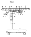
- FIG. 1 is a front view of a tiltable table embodying the invention;
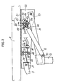
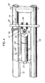
- FIG. 2 is an enlarged view in section showing a holding mechanism and a release mechanism for a top plate;
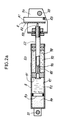
- FIG. 2a is an enlarged view in section of an air spring shown in FIG. 2;
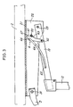
- FIG. 3 is an enlarged front view showing the construction of a pawl plate with the holding and release mechanisms omitted;
- FIG. 4 is a plan view showing a frame assembly with the top plate and a bracket removed;
- FIG. 5 is a perspective view showing a lever and a lock member; and
- FIG. 6 is an enlarged view in section showing another embodiment of top plate release mechanism.
- With reference to FIG. 1 showing a tiltable table embodying the invention, a
lift mast 12 is upwardly and downwardly movably mounted on a fixedpost 11 extending upward from a dolly 1. Twoframes 13 extend in parallel from the upper end of thelift mast 12 as an assembly. Atop plate 2 has abracket 21 on its rear side. Apivot 23 extends through the forward ends of theframes 13 and the corresponding ends ofside plates 22 of thebracket 21 to movably support thetop plate 2 on the forward portion of assembly of theframes 13. - A
pivot 55 extends through theside plates 22 of thebracket 21. Anair spring 5 is disposed between thepivot 55 and thelift mast 12. Theair spring 5 has oneend 51 pivoted to themast 12, and apiston rod 52 projecting from the air spring has fixed to its outer end abracket 54, which in turn is supported by thepivot 55. Consequently, the tilt angle of thetop plate 2 can be set and fixed by determining the length of projection of thepiston rod 52 from the cylinder as desired and locking the piston rod at the projected position. - With reference to FIG. 2a, the
air spring 5 is a commercial one and has in its interior apiston 91, compressedgas 94, workingfluid 92,release valve 96 andfree piston 93. Afirst chamber 97 and asecond chamber 98 on opposite sides of thepiston 91 are filled with theworking fluid 92. Therelease valve 96 usually holds anorifice 95 in thepiston 91 closed, preventing the flow of the workingfluid 92 and locking thepiston 91 inside the cylinder, so that the length of projection of thepiston rod 52 remains unchanged. - When the outer end of a
pin 53 projecting from the outer end of thepiston rod 52 is pushed by a pushingplate 81, therelease valve 96 opens theorifice 95, permitting the working fluid to freely flow between thefirst chamber 97 and thesecond chamber 98 on opposite sides of thepiston 91 to render thepiston 91 free to move. Thepiston 91 is moved by the expansion of thecompressed gas 94 or by pushing in the outer end of thepiston rod 52. When thepin 53 is relieved of the pressure, thepiston 91 is locked in the moved position to set thepiston rod 52 in the projected position. - The
bracket 54 fixed to the piston rod outer end is provided with release means 8 opposed to thepin 53 of theair spring 5. - As seen in FIG. 2, the release means 8 interconnects the pushing
plate 81 and alever 3 attached to the free end of thetop plate 2. - The free end of the
top plate 2 is provided with ahandle 24 with ahole 25 formed therebetween. Thelever 3 is attached at its base end to the rear side of the top plate by apivot 31 close to thehandle 24 and has a forward end extending toward thehandle 24. - With reference to FIG. 2, the base end of the
lever 3 is connected by alink member 32 to apivotal plate 33 pivoted to thebracket 21 as at 34. Thepivotal plate 33 is coupled to the pushingplate 81 of the release means 8 by a remoteflexible wire 4. - The
flexible wire 4 comprises an outer tube and an inner wire member. The outer tube has oneend 41 fixed to abracket 26 close to thepivotal plate 33, and theother end 42 fixed to thebracket 54. - The inner wire member has one
end 43 engaged in arecessed portion 35 of thepivotal plate 33, and theother end 44 engaged in acutout 82 formed in one end of the pushingplate 81. Accordingly, the remoteflexible wire 4 extends between the twobrackets - The
lever 3 exerts a pulling force which increases in accordance with the ratio of the distance of the lever grip from thepivot 31 to the distance of thelink member 32 from thepivot 31. The pressure to be exerted by the pushingplate 81 increases in accordance with the ratio of the distance of thecutout 82 from apivot 83 to the distance of the outer end of thepin 53 from thepivot 83, the pushingplate 81 being attached to thebracket 54 by thepivot 83. - As shown in FIGS. 3 and 4, one of the two
parallel frames 13 is provided with apivot 62 supporting the base end of apawl plate 61. - The
pawl plate 61 has aspring wire 64 having opposite ends which are bent at a right angle. Oneend 65 of the spring wire is engaged in theframe 13, and theother end 66 thereof is engaged in thepawl plate 61 to press acontact face 67 of thepawl plate 61 against thepivot 55. After thespring wire 64 has been engaged at its opposite ends in the frame and the pawl plate as shown in FIG. 4, theair spring 5 subsequently assembled is positioned alongside thespring wire 64 to prevent thespring wire 64 from slipping off. Thecontact face 67 of thepawl plate 64 is formed with arecess 63 which is positioned as opposed to thepivot 55 when thetop plate 2 is in its horizontal position. When an upward force or downward force is applied to thetop plate 2, with thehandle 24 and the grip of thelever 3 grasped, therelease valve 96 in theair piston 5 unlocks thepiston 5, and the top plate freely moves pivotally. The user feels a snap through thehandle 24 upon therecessed portion 63 of thepawl plate 61 fitting around thepivot 55. If thelever 3 is released from the hand at this time, thetiltable top plate 2 is held in the horizontal position. - With reference to FIGS. 1 and 5, the
lever 3 is provided with alock member 7 which is L-shaped in section. Thelock member 7 hasopposite side plates 72 each formed with adeep bore 73 and twoshallow positioning grooves lever 3 is formed on the inner face of each side portion thereof with apin 36 fittable in thebore 73 and aridge 37 corresponding to thepositioning grooves lock member 7 is pivotally movable with eachpin 36 fitted in thebore 73 between a standby position (indicated in solid line in FIG. 1) and a locking position (dot-and-dash line in FIG. 1) wherein alock plate 71 is raised to bear on the rear side of thetop plate 2. In these positions, theridge 37 fits in either one of the twopositioning grooves lock plate 71 is held in its pivotally moved position by the engagement of theridges 37 in thepositioning grooves lever 3 is held locked by thelock member 7 and will not inadvertently become released. Thus, thelock member 7, when raised, prevents the manipulation of thelever 3, consequently rendering therelease mechanism 3 inoperative and holding the top plate tilted. - FIG. 6 shows another embodiment of mechanism 8 for releasing the air piston.
- The base end of a pushing
plate 81 is pivoted as at 83 to the rear side of thebracket 21 on thetop plate 2. The base end of thelever 3 and the pushingplate 81 is interconnected by atie rod 84. - The end of the
tire rod 84 toward the pushingplate 81 has anenlarged portion 87, which is engaged in a recessedportion 63 formed in the pushingplate 81. The other end of thetie rod 84 toward the lever extends through a retaininglateral rod 85, is threaded and has an adjustingnut 86 screwed thereon. According to the embodiment of FIG. 6, the position where thepin 53 of theair spring 5 bears on the pushingplate 81 alters with the tilt angle of the top plate, such that the distance of the point of application of force from thepivot 83 is minimum to give a small lever ratio when the length of projection of thepiston rod 53 is minimum, i.e., when the gas confined in the cylinder is compressed most to give an increased pressure. - Further the distance of the point of application from the
pivot 83 is maximum to give a great lever ratio when the length of projection of the piston rod is maximum, i.e., when the gas in the cylinder is most expanded to give a decreased pressure. Consequently, the force applied by manipulating thelever 3 to pull thetie rod 84 is approximately constant despite variations in the tilt angle of the top plate. - The present invention can be embodied variously within the scope thereof as defined by the appended claims and is of course not limited to the drawings and the embodiments described above.
Claims (6)
- A tiltable table having a top plate (2) tiltably mounted on a frame (13), the tiltable table comprising:
an air spring (5) disposed between the frame (13) and the top plate (2) and having a cylinder pivoted at its one end (51) to the frame, a piston rod (52) pivoted at its outer end to the rear side of the top plate (2) and a release pin (53) projecting from the piston rod outer end, the piston rod being holdable as projected by a desired length by the air spring (5),
a pushing plate (81) movable toward and away from the release pin (53) of the air spring (5),
a lever (3) pivoted to the top plate at the free end thereof, and
release means attached at its one end to the base end of the lever (3) and at the other end thereof to the pushing plate (81) for pressing the pushing plate (81) into contact with the release pin (53) of the air spring (5) when the lever (3) is pivotally moved to thereby release the piston rod from the holding action of the air spring (5). - A tiltable table as defined in claim 1 wherein the pushing plate (81) has a base end pivoted to the outer end of the piston rod of the air spring (5) and a forward end connected to the release means, and the release pin (53) of the air spring is opposed to an intermediate position between the pivoted point of the pushing plate (81) and the point of connection of the pushing plate to the release means.
- A tiltable table as defined in claim 2 wherein the release means is a remote flexible wire (4) comprising an outer tube and an inner wire member, the outer tube having one end (41) connected to a member in the vicinity of the pivoted portion of the lever (3) and the other end (42) connected to the outer end of the piston rod (52), the inner wire member having one end (43) connected to the lever (3) and the other end (81) attached to the pushing plate (81)
- A tiltable table as defined in claim 1 wherein the pushing plate (81) has a base end pivoted to the rear side of the top plate (2) and a forward end opposed to the release pin (53) of the air spring, and the release means is connected to the pushing plate at an intermediate position between the pivoted point of the pushing plate and the point thereof opposed to the release pin.
- A tiltable table as defined in claim 1 wherein the frame (13) has pivoted thereto one end of a pawl plate (61), and the pawl plate has a contact face (67) formed on a forward end thereof and bearing on a pivot (55) on the top plate, a spring wire (64) being in the form of a bent resilient metal member and having one end (65) engaged with the frame (13) and the other end (66) engaged with the pawl plate (61) for biasing the contact face (67) into pressing contact with the pivot (55), the contact face (67) being formed with a shallow recessed portion (63) fittable to the pivot (55) when the top plate is at a predetermined tilt angle, for example, in a horizontal position.
- A tiltable table as defined in claim 1 wherein the lever (3) has pivoted thereto a lock member (7) having an arm length approximately equal to the height of the rear surface of the top plate from the lever, and the lock member temporarily prevents the manipulation of the lever.
Applications Claiming Priority (2)
| Application Number | Priority Date | Filing Date | Title |
|---|---|---|---|
| JP5139790 | 1990-05-15 | ||
| JP51397/90U | 1990-05-15 |
Publications (1)
| Publication Number | Publication Date |
|---|---|
| EP0457301A1 true EP0457301A1 (en) | 1991-11-21 |
Family
ID=12885809
Family Applications (1)
| Application Number | Title | Priority Date | Filing Date |
|---|---|---|---|
| EP91107858A Ceased EP0457301A1 (en) | 1990-05-15 | 1991-05-15 | Tiltable table |
Country Status (2)
| Country | Link |
|---|---|
| US (1) | US5131333A (en) |
| EP (1) | EP0457301A1 (en) |
Cited By (4)
| Publication number | Priority date | Publication date | Assignee | Title |
|---|---|---|---|---|
| DE19536664A1 (en) * | 1995-09-30 | 1997-04-03 | Desanta | Freestanding computer desk with adjustable keyboard support |
| US6662731B2 (en) | 2001-12-27 | 2003-12-16 | Steelcase Development Corporation | Nestable table with slotted table top |
| EP1563761A1 (en) * | 2004-02-16 | 2005-08-17 | BENYAMINE, Monique | Table, in particular school desk |
| CN108851558A (en) * | 2018-07-24 | 2018-11-23 | 合肥爱玩动漫有限公司 | A kind of support frame for cartoon design |
Families Citing this family (27)
| Publication number | Priority date | Publication date | Assignee | Title |
|---|---|---|---|---|
| US5685231A (en) * | 1992-10-05 | 1997-11-11 | Eyre; Clarence W. | Computer work station |
| US5778799A (en) * | 1992-10-05 | 1998-07-14 | Baker Manufacturing Co. | Computer work station |
| US5410971A (en) * | 1992-10-15 | 1995-05-02 | Jeff Industries, Inc. | Adjustable work station for the handicapped |
| US5326336A (en) * | 1993-02-09 | 1994-07-05 | Fredric Wemlinger | Diving board lift |
| US5431112A (en) * | 1994-03-31 | 1995-07-11 | International Material Control Systems, Inc. | Safety locking system for air-operated tilt tables |
| US5572933A (en) * | 1994-03-31 | 1996-11-12 | International Material Control Systems Inc. | Safety locking system for air-operated tilt tables |
| US5624375A (en) * | 1995-04-21 | 1997-04-29 | Ohmeda Inc. | Incubator tilt mechanism |
| US5752448A (en) * | 1995-06-07 | 1998-05-19 | Baker Manufacturing Co., Inc. | Motorized Table |
| US5601014A (en) * | 1995-06-28 | 1997-02-11 | Vestil Manufacturing Company | Lift and tilt table |
| US6354227B1 (en) * | 2000-01-11 | 2002-03-12 | Steelcase Development Corporation | Adjustable table with worksurface having write-on surface adapted for use as projection screen |
| US6571720B2 (en) * | 2001-03-22 | 2003-06-03 | Lorraine Moore | Non-swiveling height adjustable podium |
| DE20118884U1 (en) | 2001-10-02 | 2002-02-07 | Cornelius, Christian, 32423 Minden | Tilted, swivel plate |
| US7506592B2 (en) * | 2003-08-27 | 2009-03-24 | Jaco, Inc. | Adjustable height workstation for laptop or tablet computers |
| US20050120922A1 (en) * | 2003-12-05 | 2005-06-09 | Brooks Nolan T. | Folding work table |
| WO2006038649A1 (en) * | 2004-10-05 | 2006-04-13 | Okamura Corporation | Desk |
| US20060273703A1 (en) * | 2005-06-07 | 2006-12-07 | Hardt John Ii | Pneumatic lift and storage apparatus |
| US20070120338A1 (en) * | 2005-11-29 | 2007-05-31 | Morgan William W | Material carrying and lifting apparatus having a pivoting tabletop |
| US7677184B2 (en) * | 2005-12-15 | 2010-03-16 | Steelcase Development Corporation | Flip top table |
| US7631604B2 (en) * | 2006-05-08 | 2009-12-15 | Tsung-Chieh Huang | Telescopic and foldable table |
| US8297208B2 (en) * | 2009-06-09 | 2012-10-30 | Ditto Sales, Inc. | Tilting tabletop mechanism |
| JP6306042B2 (en) | 2012-12-11 | 2018-04-04 | コーニンクレッカ フィリップス エヌ ヴェKoninklijke Philips N.V. | Method and system for tilting an infant care medical device |
| US9102410B2 (en) * | 2013-04-04 | 2015-08-11 | B/E Aerospace, Inc. | Vertically stowed tray table assembly with translational movement |
| EP3620079B1 (en) * | 2018-09-06 | 2022-11-02 | IHS Global Design Pty Ltd | Room service table |
| US11284710B1 (en) * | 2020-11-15 | 2022-03-29 | Foshan Nanhai Longshang Office Furniture Co., Ltd. | Adjustment device that controls a tilting angle of a table top |
| US12178321B2 (en) * | 2022-09-02 | 2024-12-31 | Lakewood Candies LLC | Hybrid art table/easel |
| US12569059B2 (en) * | 2024-03-20 | 2026-03-10 | Teknion Limited | Workstation with tilt-adjustable tabletop |
| US12543849B1 (en) * | 2025-03-07 | 2026-02-10 | Xiufang Zhang | Angle-adjustable flip table |
Citations (4)
| Publication number | Priority date | Publication date | Assignee | Title |
|---|---|---|---|---|
| NL7812330A (en) * | 1978-12-20 | 1980-06-24 | Golden Inventions I O B V | Mechanism for table or bed supported on single column - has rails and rollers permitting limited horizontal movement in two directions of top on column |
| FR2599774A1 (en) * | 1986-06-06 | 1987-12-11 | Rozand Bernard | Interior locking of a door by blocking the handle |
| DE3815809A1 (en) * | 1987-05-15 | 1988-11-24 | Okamura Corp | Gas-spring actuation lever mounting device - uses plastics type bearing block with semicircular shaped larger periphery |
| DE8813003U1 (en) * | 1988-10-15 | 1990-02-15 | Wini Büromöbel Georg Schmidt GmbH & Co. KG, 3256 Coppenbrügge | Height adjustable office table |
Family Cites Families (6)
| Publication number | Priority date | Publication date | Assignee | Title |
|---|---|---|---|---|
| US3347399A (en) * | 1966-01-17 | 1967-10-17 | Earl H Ensinger | Barrel dumper |
| US4180002A (en) * | 1978-07-12 | 1979-12-25 | American Hospital Supply Corporation | Tiltable table |
| US4337670A (en) * | 1979-10-02 | 1982-07-06 | Sico Incorporated | Yieldable multi-function linkage apparatus for powered pivoting loads |
| JPS58117132U (en) * | 1982-02-01 | 1983-08-10 | 株式会社岡村製作所 | folding table |
| DE3512201A1 (en) * | 1985-04-03 | 1986-10-09 | Inaba Seisakusho Ltd., Tokio/Tokyo | TABLE WITH A TABLE BASE |
| US4703701A (en) * | 1985-04-19 | 1987-11-03 | Inaba Seisakusho Ltd. | Desk with height and angle adjustable table top |
-
1991
- 1991-05-13 US US07/699,986 patent/US5131333A/en not_active Expired - Fee Related
- 1991-05-15 EP EP91107858A patent/EP0457301A1/en not_active Ceased
Patent Citations (4)
| Publication number | Priority date | Publication date | Assignee | Title |
|---|---|---|---|---|
| NL7812330A (en) * | 1978-12-20 | 1980-06-24 | Golden Inventions I O B V | Mechanism for table or bed supported on single column - has rails and rollers permitting limited horizontal movement in two directions of top on column |
| FR2599774A1 (en) * | 1986-06-06 | 1987-12-11 | Rozand Bernard | Interior locking of a door by blocking the handle |
| DE3815809A1 (en) * | 1987-05-15 | 1988-11-24 | Okamura Corp | Gas-spring actuation lever mounting device - uses plastics type bearing block with semicircular shaped larger periphery |
| DE8813003U1 (en) * | 1988-10-15 | 1990-02-15 | Wini Büromöbel Georg Schmidt GmbH & Co. KG, 3256 Coppenbrügge | Height adjustable office table |
Cited By (5)
| Publication number | Priority date | Publication date | Assignee | Title |
|---|---|---|---|---|
| DE19536664A1 (en) * | 1995-09-30 | 1997-04-03 | Desanta | Freestanding computer desk with adjustable keyboard support |
| DE19536664C2 (en) * | 1995-09-30 | 1998-04-30 | Desanta | Computer desk |
| US6662731B2 (en) | 2001-12-27 | 2003-12-16 | Steelcase Development Corporation | Nestable table with slotted table top |
| EP1563761A1 (en) * | 2004-02-16 | 2005-08-17 | BENYAMINE, Monique | Table, in particular school desk |
| CN108851558A (en) * | 2018-07-24 | 2018-11-23 | 合肥爱玩动漫有限公司 | A kind of support frame for cartoon design |
Also Published As
| Publication number | Publication date |
|---|---|
| US5131333A (en) | 1992-07-21 |
Similar Documents
| Publication | Publication Date | Title |
|---|---|---|
| US5131333A (en) | Tiltable table | |
| US5664842A (en) | Height-adjustable armrest unit for a chair | |
| US6648315B1 (en) | Clamping device having indirect driving mechanism | |
| US6029585A (en) | Lift mechanism | |
| US7104203B2 (en) | Height adjustable device for a retractable tube assembly | |
| US20060045709A1 (en) | Patient lift with support legs that spread over two ranges of motion | |
| JPH064479B2 (en) | Jealousy | |
| US11284710B1 (en) | Adjustment device that controls a tilting angle of a table top | |
| US20040065238A1 (en) | Elevational adjusting device using air pressure rod to lift object | |
| US6443075B1 (en) | Safety interlock braking system for height adjustable table | |
| CN1477442A (en) | Height adjusting system of projector | |
| KR101788613B1 (en) | Anti-upside down device for furniture | |
| USRE35805E (en) | Two-way actuator for a chair height adjustment mechanism | |
| EP2060203A2 (en) | Operating device | |
| JP3509073B2 (en) | Bedside table | |
| US20040065239A1 (en) | Elevational adjusting device using air pressure rod to lift object | |
| JP2543760Y2 (en) | Ramp | |
| JPH0731979Y2 (en) | Tilt table | |
| JP2546084B2 (en) | Toggle parking brake lever device | |
| US5476049A (en) | Motion control apparatus | |
| JPH0731978Y2 (en) | Ramp | |
| US20260103364A1 (en) | Friction lock bar jack for construction | |
| KR100715506B1 (en) | Door stopper | |
| JP3286284B2 (en) | Footrest fixing device | |
| JP2003079438A (en) | Lifting table |
Legal Events
| Date | Code | Title | Description |
|---|---|---|---|
| PUAI | Public reference made under article 153(3) epc to a published international application that has entered the european phase |
Free format text: ORIGINAL CODE: 0009012 |
|
| AK | Designated contracting states |
Kind code of ref document: A1 Designated state(s): CH DE FR GB LI |
|
| 17P | Request for examination filed |
Effective date: 19920429 |
|
| 17Q | First examination report despatched |
Effective date: 19940913 |
|
| STAA | Information on the status of an ep patent application or granted ep patent |
Free format text: STATUS: THE APPLICATION HAS BEEN REFUSED |
|
| 18R | Application refused |
Effective date: 19951022 |