EP0457400A1 - Ensemble sondé pour tuyaux métalliques insérés l'un dans l'autre - Google Patents
Ensemble sondé pour tuyaux métalliques insérés l'un dans l'autre Download PDFInfo
- Publication number
- EP0457400A1 EP0457400A1 EP91201118A EP91201118A EP0457400A1 EP 0457400 A1 EP0457400 A1 EP 0457400A1 EP 91201118 A EP91201118 A EP 91201118A EP 91201118 A EP91201118 A EP 91201118A EP 0457400 A1 EP0457400 A1 EP 0457400A1
- Authority
- EP
- European Patent Office
- Prior art keywords
- clamps
- pipe
- pair
- welding
- supports
- Prior art date
- Legal status (The legal status is an assumption and is not a legal conclusion. Google has not performed a legal analysis and makes no representation as to the accuracy of the status listed.)
- Granted
Links
- 238000003466 welding Methods 0.000 title claims abstract description 17
- 229910052751 metal Inorganic materials 0.000 title claims description 5
- 239000002184 metal Substances 0.000 title claims description 5
- 239000000919 ceramic Substances 0.000 claims abstract description 6
- 238000003780 insertion Methods 0.000 claims abstract description 3
- 230000037431 insertion Effects 0.000 claims abstract description 3
- 238000010891 electric arc Methods 0.000 claims description 7
- 239000004411 aluminium Substances 0.000 description 6
- 229910052782 aluminium Inorganic materials 0.000 description 6
- XAGFODPZIPBFFR-UHFFFAOYSA-N aluminium Chemical compound [Al] XAGFODPZIPBFFR-UHFFFAOYSA-N 0.000 description 6
- RYGMFSIKBFXOCR-UHFFFAOYSA-N Copper Chemical compound [Cu] RYGMFSIKBFXOCR-UHFFFAOYSA-N 0.000 description 5
- 229910052802 copper Inorganic materials 0.000 description 5
- 239000010949 copper Substances 0.000 description 5
- 239000000463 material Substances 0.000 description 2
- 230000008878 coupling Effects 0.000 description 1
- 238000010168 coupling process Methods 0.000 description 1
- 238000005859 coupling reaction Methods 0.000 description 1
- 230000000694 effects Effects 0.000 description 1
- 238000010438 heat treatment Methods 0.000 description 1
- 238000004021 metal welding Methods 0.000 description 1
- 238000000034 method Methods 0.000 description 1
Images


Classifications
-
- B—PERFORMING OPERATIONS; TRANSPORTING
- B23—MACHINE TOOLS; METAL-WORKING NOT OTHERWISE PROVIDED FOR
- B23K—SOLDERING OR UNSOLDERING; WELDING; CLADDING OR PLATING BY SOLDERING OR WELDING; CUTTING BY APPLYING HEAT LOCALLY, e.g. FLAME CUTTING; WORKING BY LASER BEAM
- B23K11/00—Resistance welding; Severing by resistance heating
- B23K11/08—Seam welding not restricted to one of the preceding subgroups
- B23K11/093—Seam welding not restricted to one of the preceding subgroups for curved planar seams
- B23K11/0935—Seam welding not restricted to one of the preceding subgroups for curved planar seams of tube sections
Definitions
- the present invention relates to a welding unit for metal pipes inserted one inside the other.
- electric arc units which basically comprise two pairs of clamps suitable for grasping and holding the respective pipes in an inserted and clamped position during the time in which an electric arc is supplied to the welding area.
- the heat of the electric arc determines the reciprocal welding of the two materials and thus of the two pipes.
- the structure of the clamps is such that the heat given off is not capable of producing a weld that is uniform along the entire connecting area between the copper pipe and that of aluminium.
- the object of the present invention is to accomplish a weld that is as homogeneous as possible along the entire contact area between the pipes.
- a welding unit for a first and a second metal pipe inserted one inside the other comprising a first and a second pair of clamps supplied electrically for supporting and clamping, respectively, said first and second pipe to be welded, characterized in that each of the clamps of the second pair comprises a ceramic insert in contact with said second pipe in the area of insertion and welding of the first pipe.
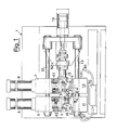
- the welding unit comprises a fixed frame 1 with which there is associated a first and a second pair of supports 3, 5 and 2, 4 for a first and a second pair of metal clamps 20, 21 and 22, 23, destined to support a copper pipe 30 and an aluminium pipe 31, respectively, inserted one inside the other.
- the first and the second pair of supports comprises respective lower supports 3, 2 and upper supports 5, 4.
- the upper supports 5, 4 are fastened to vertical stems 61, 62 which slide inside structural blocks 7, 6 under the action of cylinders 9, 8.
- the lower supports 2, 3 are in turn fastened to structural blocks 11, 10 which determine their vertical position with respect to the fixed frame 1.
- the blocks 6, 7, 10, 11 are traversed by bars 12, 13 that horizontally guide blocks 7, 10 under the action of a hydraulic cylinder 14 through a horizontal stem 15 which slides in a support 82 of the guide bars 12, 13.
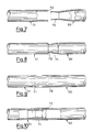
- the supports 3, 5 there are associated by means of screws 16, 17 the clamps 20, 21, each with a coupling face having a semicylindrical groove 63, 64 (Fig.s 2, 4 and 5).
- the supports 2, 4 there are associated by means of screws 18, 19 the clamps 22, 23, each similarly having a semicylindrical groove 65, 66 (Fig.s 3 - 6), with which there are associated by means of screws 24, 25 similarly grooved ceramic inserts 26, 27.
- the lower supports 3, 2, and thus the clamps 20, 22, are connected electrically to a voltage source 70 suitable for producing an electric arc across the two pairs of clamps 20, 21 and 22, 23.
Landscapes
- Engineering & Computer Science (AREA)
- Mechanical Engineering (AREA)
- Arc Welding In General (AREA)
- Butt Welding And Welding Of Specific Article (AREA)
- Non-Disconnectible Joints And Screw-Threaded Joints (AREA)
Applications Claiming Priority (2)
| Application Number | Priority Date | Filing Date | Title |
|---|---|---|---|
| IT2034690 | 1990-05-17 | ||
| IT20346A IT1241151B (it) | 1990-05-17 | 1990-05-17 | Apparecchio di saldatura per tubetti metallici innestati uno nell'altro |
Publications (2)
| Publication Number | Publication Date |
|---|---|
| EP0457400A1 true EP0457400A1 (fr) | 1991-11-21 |
| EP0457400B1 EP0457400B1 (fr) | 1994-08-10 |
Family
ID=11165914
Family Applications (1)
| Application Number | Title | Priority Date | Filing Date |
|---|---|---|---|
| EP91201118A Expired - Lifetime EP0457400B1 (fr) | 1990-05-17 | 1991-05-10 | Ensemble sondé pour tuyaux métalliques insérés l'un dans l'autre |
Country Status (5)
| Country | Link |
|---|---|
| EP (1) | EP0457400B1 (fr) |
| AT (1) | ATE109704T1 (fr) |
| BR (1) | BR9101990A (fr) |
| DE (1) | DE69103330T2 (fr) |
| IT (1) | IT1241151B (fr) |
Cited By (3)
| Publication number | Priority date | Publication date | Assignee | Title |
|---|---|---|---|---|
| WO2002053317A1 (fr) * | 2001-01-05 | 2002-07-11 | Magna International Inc. | Ensemble de soudage a extremites conductrices emboitables |
| US6713707B2 (en) | 1997-10-16 | 2004-03-30 | Magna International, Inc. | Welding material and method without carrier |
| CN111872627A (zh) * | 2020-07-20 | 2020-11-03 | 常州市常蒸制冷科技有限公司 | 一种全自动铜铝管生产装置 |
Families Citing this family (3)
| Publication number | Priority date | Publication date | Assignee | Title |
|---|---|---|---|---|
| US6621037B2 (en) | 1997-10-16 | 2003-09-16 | Magna International Inc. | Welding material with conductive sheet and method |
| US6689982B2 (en) | 1997-10-16 | 2004-02-10 | Magna International, Inc. | Apparatus and method for welding aluminum tubes |
| CN100460129C (zh) * | 2006-05-25 | 2009-02-11 | 珠海格力电器股份有限公司 | 铜铝复合管道、加工设备及其加工方法 |
Citations (1)
| Publication number | Priority date | Publication date | Assignee | Title |
|---|---|---|---|---|
| DE938206C (de) * | 1939-12-03 | 1956-01-26 | Siemens Ag | Abbrenn- und Stumpfschweissverfahren zur Verbindung von Kupfer- mit Aluminiumteilen od. dgl. |
-
1990
- 1990-05-17 IT IT20346A patent/IT1241151B/it active IP Right Grant
-
1991
- 1991-05-10 AT AT91201118T patent/ATE109704T1/de not_active IP Right Cessation
- 1991-05-10 DE DE69103330T patent/DE69103330T2/de not_active Expired - Fee Related
- 1991-05-10 EP EP91201118A patent/EP0457400B1/fr not_active Expired - Lifetime
- 1991-05-15 BR BR919101990A patent/BR9101990A/pt not_active IP Right Cessation
Patent Citations (1)
| Publication number | Priority date | Publication date | Assignee | Title |
|---|---|---|---|---|
| DE938206C (de) * | 1939-12-03 | 1956-01-26 | Siemens Ag | Abbrenn- und Stumpfschweissverfahren zur Verbindung von Kupfer- mit Aluminiumteilen od. dgl. |
Non-Patent Citations (1)
| Title |
|---|
| PATENT ABSTRACTS OF JAPAN vol. 11, no. 155 (M-589)(2602) 20 May 1987, & JP-A-61 286076 (HITACHI LTD) 16 December 1986, * |
Cited By (4)
| Publication number | Priority date | Publication date | Assignee | Title |
|---|---|---|---|---|
| US6713707B2 (en) | 1997-10-16 | 2004-03-30 | Magna International, Inc. | Welding material and method without carrier |
| US6566624B2 (en) | 2000-03-03 | 2003-05-20 | Magna International Inc. | Welding assembly with nestable conductive ends |
| WO2002053317A1 (fr) * | 2001-01-05 | 2002-07-11 | Magna International Inc. | Ensemble de soudage a extremites conductrices emboitables |
| CN111872627A (zh) * | 2020-07-20 | 2020-11-03 | 常州市常蒸制冷科技有限公司 | 一种全自动铜铝管生产装置 |
Also Published As
| Publication number | Publication date |
|---|---|
| ATE109704T1 (de) | 1994-08-15 |
| BR9101990A (pt) | 1991-12-24 |
| IT9020346A0 (it) | 1990-05-17 |
| IT1241151B (it) | 1993-12-29 |
| EP0457400B1 (fr) | 1994-08-10 |
| IT9020346A1 (it) | 1991-11-17 |
| DE69103330T2 (de) | 1995-02-23 |
| DE69103330D1 (de) | 1994-09-15 |
Similar Documents
| Publication | Publication Date | Title |
|---|---|---|
| US5389760A (en) | Flash butt welding facility | |
| GB2058636A (en) | Apparatus for positioning and securing components of a workpiece | |
| EP0457400A1 (fr) | Ensemble sondé pour tuyaux métalliques insérés l'un dans l'autre | |
| CN110154379B (zh) | 一种线束套接热缩管设备及线束套接热缩管方法 | |
| CN108672874A (zh) | 一种框架断路器触头产热浮动焊接装置 | |
| GB2188269A (en) | Welding by induction heating | |
| US4170449A (en) | Clamping frame for plastic forming apparatus | |
| CN108788572A (zh) | 一种金属组合焊接用定位机构 | |
| CN108581158A (zh) | 一种竖向设置的建筑用对焊机 | |
| CN220480523U (zh) | 一种用于金属棒料对焊的储能焊设备 | |
| CN108406188B (zh) | 一种缝纫机底座支架焊接专机 | |
| CN108526797A (zh) | 一种钢板焊接装置及其使用方法 | |
| US4798321A (en) | Panelizing machine and method for use | |
| KR101949368B1 (ko) | 삼중 복합 전극팁 및 병렬형 삼중 가압에 의한 전기저항 스폿용접기 | |
| EP0025778A1 (fr) | Résistance électrique chauffante du type épingle à cheveux et procédé pour sa fabrication | |
| US2011926A (en) | Electric welding | |
| US3419699A (en) | Welding machine for metal grids | |
| JPH05244755A (ja) | コイル成形装置 | |
| US4908490A (en) | Technology and equipment of the stressed skin sheet covering for large passenger vehicles | |
| CN213163798U (zh) | 一种焊接夹具切换装置 | |
| US3341684A (en) | Resistance butt welding machine | |
| CN220072912U (zh) | 一种全自动侧弯成形弯管机 | |
| CN217891864U (zh) | 一种多合点线束热缩管收缩机 | |
| CN207872974U (zh) | 一种拉网四角焊接机 | |
| SU1727523A3 (ru) | Способ контактной сварки пластинчатого тела внутри трубчатого металлического стержн и установка дл его осуществлени |
Legal Events
| Date | Code | Title | Description |
|---|---|---|---|
| PUAI | Public reference made under article 153(3) epc to a published international application that has entered the european phase |
Free format text: ORIGINAL CODE: 0009012 |
|
| AK | Designated contracting states |
Kind code of ref document: A1 Designated state(s): AT BE CH DE DK ES FR GB GR IT LI LU NL SE |
|
| 17P | Request for examination filed |
Effective date: 19920304 |
|
| 17Q | First examination report despatched |
Effective date: 19930127 |
|
| GRAA | (expected) grant |
Free format text: ORIGINAL CODE: 0009210 |
|
| AK | Designated contracting states |
Kind code of ref document: B1 Designated state(s): AT BE CH DE DK ES FR GB GR IT LI LU NL SE |
|
| PG25 | Lapsed in a contracting state [announced via postgrant information from national office to epo] |
Ref country code: NL Effective date: 19940810 Ref country code: LI Effective date: 19940810 Ref country code: GR Free format text: LAPSE BECAUSE OF FAILURE TO SUBMIT A TRANSLATION OF THE DESCRIPTION OR TO PAY THE FEE WITHIN THE PRESCRIBED TIME-LIMIT Effective date: 19940810 Ref country code: ES Free format text: THE PATENT HAS BEEN ANNULLED BY A DECISION OF A NATIONAL AUTHORITY Effective date: 19940810 Ref country code: DK Effective date: 19940810 Ref country code: CH Effective date: 19940810 Ref country code: BE Effective date: 19940810 Ref country code: AT Effective date: 19940810 |
|
| REF | Corresponds to: |
Ref document number: 109704 Country of ref document: AT Date of ref document: 19940815 Kind code of ref document: T |
|
| REF | Corresponds to: |
Ref document number: 69103330 Country of ref document: DE Date of ref document: 19940915 |
|
| ITF | It: translation for a ep patent filed | ||
| PG25 | Lapsed in a contracting state [announced via postgrant information from national office to epo] |
Ref country code: SE Effective date: 19941110 |
|
| REG | Reference to a national code |
Ref country code: CH Ref legal event code: PL |
|
| ET | Fr: translation filed | ||
| NLV1 | Nl: lapsed or annulled due to failure to fulfill the requirements of art. 29p and 29m of the patents act | ||
| PG25 | Lapsed in a contracting state [announced via postgrant information from national office to epo] |
Ref country code: LU Free format text: LAPSE BECAUSE OF NON-PAYMENT OF DUE FEES Effective date: 19950531 |
|
| PLBE | No opposition filed within time limit |
Free format text: ORIGINAL CODE: 0009261 |
|
| STAA | Information on the status of an ep patent application or granted ep patent |
Free format text: STATUS: NO OPPOSITION FILED WITHIN TIME LIMIT |
|
| 26N | No opposition filed | ||
| REG | Reference to a national code |
Ref country code: GB Ref legal event code: IF02 |
|
| PGFP | Annual fee paid to national office [announced via postgrant information from national office to epo] |
Ref country code: GB Payment date: 20030514 Year of fee payment: 13 |
|
| PGFP | Annual fee paid to national office [announced via postgrant information from national office to epo] |
Ref country code: FR Payment date: 20030528 Year of fee payment: 13 Ref country code: DE Payment date: 20030528 Year of fee payment: 13 |
|
| PG25 | Lapsed in a contracting state [announced via postgrant information from national office to epo] |
Ref country code: GB Free format text: LAPSE BECAUSE OF NON-PAYMENT OF DUE FEES Effective date: 20040510 |
|
| PG25 | Lapsed in a contracting state [announced via postgrant information from national office to epo] |
Ref country code: DE Free format text: LAPSE BECAUSE OF NON-PAYMENT OF DUE FEES Effective date: 20041201 |
|
| GBPC | Gb: european patent ceased through non-payment of renewal fee |
Effective date: 20040510 |
|
| PG25 | Lapsed in a contracting state [announced via postgrant information from national office to epo] |
Ref country code: FR Free format text: LAPSE BECAUSE OF NON-PAYMENT OF DUE FEES Effective date: 20050131 |
|
| REG | Reference to a national code |
Ref country code: FR Ref legal event code: ST |
|
| PG25 | Lapsed in a contracting state [announced via postgrant information from national office to epo] |
Ref country code: IT Free format text: LAPSE BECAUSE OF NON-PAYMENT OF DUE FEES;WARNING: LAPSES OF ITALIAN PATENTS WITH EFFECTIVE DATE BEFORE 2007 MAY HAVE OCCURRED AT ANY TIME BEFORE 2007. THE CORRECT EFFECTIVE DATE MAY BE DIFFERENT FROM THE ONE RECORDED. Effective date: 20050510 |