EP0457475A2 - Braking mechanism - Google Patents
Braking mechanism Download PDFInfo
- Publication number
- EP0457475A2 EP0457475A2 EP91304106A EP91304106A EP0457475A2 EP 0457475 A2 EP0457475 A2 EP 0457475A2 EP 91304106 A EP91304106 A EP 91304106A EP 91304106 A EP91304106 A EP 91304106A EP 0457475 A2 EP0457475 A2 EP 0457475A2
- Authority
- EP
- European Patent Office
- Prior art keywords
- braking
- members
- torque
- shaft
- casing
- Prior art date
- Legal status (The legal status is an assumption and is not a legal conclusion. Google has not performed a legal analysis and makes no representation as to the accuracy of the status listed.)
- Withdrawn
Links
Images


Classifications
-
- F—MECHANICAL ENGINEERING; LIGHTING; HEATING; WEAPONS; BLASTING
- F16—ENGINEERING ELEMENTS AND UNITS; GENERAL MEASURES FOR PRODUCING AND MAINTAINING EFFECTIVE FUNCTIONING OF MACHINES OR INSTALLATIONS; THERMAL INSULATION IN GENERAL
- F16D—COUPLINGS FOR TRANSMITTING ROTATION; CLUTCHES; BRAKES
- F16D59/00—Self-acting brakes, e.g. coming into operation at a predetermined speed
-
- F—MECHANICAL ENGINEERING; LIGHTING; HEATING; WEAPONS; BLASTING
- F16—ENGINEERING ELEMENTS AND UNITS; GENERAL MEASURES FOR PRODUCING AND MAINTAINING EFFECTIVE FUNCTIONING OF MACHINES OR INSTALLATIONS; THERMAL INSULATION IN GENERAL
- F16D—COUPLINGS FOR TRANSMITTING ROTATION; CLUTCHES; BRAKES
- F16D67/00—Combinations of couplings and brakes; Combinations of clutches and brakes
- F16D67/02—Clutch-brake combinations
-
- F—MECHANICAL ENGINEERING; LIGHTING; HEATING; WEAPONS; BLASTING
- F16—ENGINEERING ELEMENTS AND UNITS; GENERAL MEASURES FOR PRODUCING AND MAINTAINING EFFECTIVE FUNCTIONING OF MACHINES OR INSTALLATIONS; THERMAL INSULATION IN GENERAL
- F16D—COUPLINGS FOR TRANSMITTING ROTATION; CLUTCHES; BRAKES
- F16D65/00—Parts or details
- F16D65/02—Braking members; Mounting thereof
- F16D2065/024—Braking members; Mounting thereof the braking surface being inclined with respect to the rotor's axis of rotation at an angle other than 90 degrees, e.g. comprising a conical rotor
-
- F—MECHANICAL ENGINEERING; LIGHTING; HEATING; WEAPONS; BLASTING
- F16—ENGINEERING ELEMENTS AND UNITS; GENERAL MEASURES FOR PRODUCING AND MAINTAINING EFFECTIVE FUNCTIONING OF MACHINES OR INSTALLATIONS; THERMAL INSULATION IN GENERAL
- F16D—COUPLINGS FOR TRANSMITTING ROTATION; CLUTCHES; BRAKES
- F16D2125/00—Components of actuators
- F16D2125/18—Mechanical mechanisms
- F16D2125/20—Mechanical mechanisms converting rotation to linear movement or vice versa
- F16D2125/34—Mechanical mechanisms converting rotation to linear movement or vice versa acting in the direction of the axis of rotation
- F16D2125/36—Helical cams, Ball-rotating ramps
-
- F—MECHANICAL ENGINEERING; LIGHTING; HEATING; WEAPONS; BLASTING
- F16—ENGINEERING ELEMENTS AND UNITS; GENERAL MEASURES FOR PRODUCING AND MAINTAINING EFFECTIVE FUNCTIONING OF MACHINES OR INSTALLATIONS; THERMAL INSULATION IN GENERAL
- F16D—COUPLINGS FOR TRANSMITTING ROTATION; CLUTCHES; BRAKES
- F16D2125/00—Components of actuators
- F16D2125/18—Mechanical mechanisms
- F16D2125/58—Mechanical mechanisms transmitting linear movement
- F16D2125/66—Wedges
-
- F—MECHANICAL ENGINEERING; LIGHTING; HEATING; WEAPONS; BLASTING
- F16—ENGINEERING ELEMENTS AND UNITS; GENERAL MEASURES FOR PRODUCING AND MAINTAINING EFFECTIVE FUNCTIONING OF MACHINES OR INSTALLATIONS; THERMAL INSULATION IN GENERAL
- F16D—COUPLINGS FOR TRANSMITTING ROTATION; CLUTCHES; BRAKES
- F16D2129/00—Type of operation source for auxiliary mechanisms
- F16D2129/04—Mechanical
- F16D2129/043—Weights
Definitions
- THIS INVENTION relates to a braking mechanism which responds automatically to a reversal in an applied torque by applying a brake.
- Such a mechanism may be used to protect a load from "running away” if a driving torque falls beneath a certain value, or for interrupting a transmission of drive between a motor and a load.
- An inclined travelling slat conveyor required to lift a distributed load between two levels can cause extensive damage if there is a failure of its operating motor.
- the loss of driving torque may cause the distributed load on the conveyor to take charge, and reverse the direction of movement of the conveyor. Unless precautions are taken to prevent it, the distributed load is then deposited at the lower end of the conveyor with serious consequences to equipment and personnel at the lower level.
- a braking mechanism which becomes automatically effective when there is a reversal in the direction of torque, comprises two members having a common axis and between which relative rotation about the axis occurs when there is a reversal in the direction of the applied torque; a housing surrounding the two members; a first braking surface provided on one of the members and a second, complementary and opposed braking surface provided on the housing; first means operating to accommodate change in the spacing between the two members to control the extent of the braking; second means responsive to a reversal in torque direction to permit change in the relative angular positions of the members; camming means incorporating thrust-resistant means and responsive to the change in the relative angular positions of the members to alter the spacing between the members; and resilient means for biassing the braking surfaces towards one another to induce the required braking action promptly when the direction of torque is reversed.
- both members rotate and each is equipped with its own braking surface which engages a respective braking surface on the surrounding housing.
- the camming means comprises pairs of recesses formed on opposed faces, respectively, of the members.
- the recesses are suitably arcuate about the common axis and each may be tear-shaped with the tapered ends of the tears of each pair of recesses extending respectively in opposite directions about the common axis.
- the thrust-resistant means is suitably a hard ball. If the torque direction through the mechanism reverses, the angular displacement between the members causes the ball to force the members apart so that braking is increased.
- the resilient biassing means which may be a compression spring or springs located between the two members.
- part of the drive transmitted through the mechanism is used to operate a hydraulic pump providing a hydraulic cushion between the braking surfaces so that they are forced apart and the wear on them is minimised when the direction of the torque transmission through the mechanism is in the desired direction. If the torque is reversed, braking immediately occurs as the braking surfaces are forced against one another. A reduction in the speed of rotation of the members with respect to the housing then ensues, and the output pressure of the pump falls. This reduces the effectiveness of the hydraulic cushion between the braking surfaces which can therefore contact one another more forceably to enhance the braking effect.
- one of the two engaging braking surfaces always to be made from a softer material than the other braking surface.
- a braking mechanism which becomes automatically effective when there is a reversal in the direction of applied torque, includes two members turned by the applied torque about a common axis and providing at least one braking surface engageable with a complementary braking surface of a surrounding housing, the two members being angularly displaceable and relatively axially moveable with respect to one another and having camming means arcuate about their common axis and engaged by thrust-resistant means which allow relative rotation of the members to bring different parts of the camming means into engagement with the thrust-resistant means and so vary the spacing between the members, the profiles of the camming means being so chosen that relative rotation of one of the members in one direction of rotation with respect to the other and produced by a reversal in the applied torque, causes the spacing between the members to change and bring said one braking surface into braking engagement with the complementary braking surface of the housing.
- each of the members has a braking surface.
- the two members comprise opposed spaced discs mounted slackly on a common shaft so as to permit them relative angular movement and axial movement, with respect to one another, while allowing both discs to be driven.
- the discs conveniently are provided on their remote faces with frusto-conical braking surfaces. If one disc turns with respect to the other in a direction which increases the effective axial thickness of the camming means between them, the two discs are thrust apart and braking ensues.
- the two members In a version of the invention used in a supervisory role to protect a load driven directly by a prime-mover, the two members having eccentric abutment surfaces at the same radius from their common axis. Rotation of one of the members in one direction by the prime-mover causes the abutments to engage and transmit the rotational drive to the other member. In this situation the assembly of camming means and thrust-resistant means allows the members to assume positions at which braking is a minimum. If now the applied torque is reversed, the abutment surfaces move apart and different parts of the camming surfaces are now borne on by the thrust-resistant means. The two members are urged apart as a consequence, and braking ensues.
- the second member is provided with a manually operable rotational drive which allows it to be turned gradually in the direction of reengagement of the abutment surfaces.
- the first member under the action of the applied load torque, follows this movement.
- the load can thus be manually controlled in safety after the braking mechanism has operated.
- the mechanism of Figure 1 comprises a fixed casing 1 having aligned bores 2 and 3 threaded by respective shafts 4 and 5.
- Annular frusto-conical braking surfaces 6 and 7 are provided on opposite sides of a central cavity 8 in the casing 1.
- the shaft 4 carries outside the casing 1 a load pinion 11, and inside the casing it has slideably splined to it a first frusto-conical member 12 of disc shape.
- the shaft 5 is connected outside the casing to a drive motor 13, and inside the casing it is slackly keyed, as shown in figure 2, to a second frusto-conical member 14 also of disc shape.
- the two members 12 and 14 have respective braking surfaces 15, 16 on their remote faces which are complementary to the braking surfaces 6 and 7 of the casing 1.
- a light compression spring 19 provides a resilient bias which maintains the members 12, 14 in gentle rubbing engagement with the braking surfaces 6, 7.
- the shaft 5 extends across the cavity 8 and has its terminal portion 17 slackly keyed to the first member 12 in the manner shown in figure 2.
- the members 12, 14 are permitted limited angular movement and axial movement with respect to one another on the shaft 5.
- the opposed faces of the member 12 and 14 carry respectively opposed camming surfaces 20, 21 which are arcuate in shape and centred on the common axis of rotation of the members.
- the camming surfaces have respectively concave and convex, chevron-shaped cross-sections as shown in figure 1.
- Caged steel balls 22, providing thrust resistant means, are located between the camming surfaces. The extent to which the chevron face of the camming surface 21 projects from the face of the member 14, increases progressively around its arc.
- the load pinion moves the member 12 angularly with respect to the member 14, the slack keying on the shaft 5 permitting this angular movement.
- the effect of the angular movement is to bring different parts of the camming surfaces 20, 21 opposite the balls 22 so that the members 12, 14 are forced apart and their braking surfaces 15, 16 are brought into firm braking engagement with the complementary braking surfaces 6, 7 of the casing. Braking of the load pinion then ensues.
- a direct drive transmission connection is established from the motor 113 to a load pinion 111 by way of a drive pinion 130 fixed to the shaft 105.
- the load driven by the pinion 111 is an inclined slat conveyor 131 having parallel belt runs equipped with slats which lift a distributed load between two levels. A dangerous situation can develop with such an arrangement if power is removed from the motor 113 as this enables the load on the conveyor to descend out of control, by back-driving the motor, with the serious risk of consequences to a loading station at the lower end of the conveyor.
- the member 114 faces a member 112 and they are provided on their remote surface with frusto-conical braking surfaces 115, 116 positioned to be engageable with complementary braking surfaces 106, 107 on the casing 101.
- the member 112 is slackly keyed to a shaft 134 which is coaxially arranged with respect to the shaft 105 and has a square cross-section terminal portion 135 outside the casing 101 to enable a manually operable spanner 136 to be applied to it to turn the member 112.
- the opposed faces of the member 112, 114 are provided at generally diametrically opposite positions with two assemblies respectively.
- the first assembly comprises a pair of abutment elements 140, 141, which project from respective members 112, 114, at the same radius from their common axis of rotation. These abutment elements engage one another when the motor 113 is driving in a direction which operates the conveyor in a load-lifting direction. The rotation of the shaft 105 is then transmitted to the two members 112, 114.
- the second assembly comprises a pair of arcuate camming faces 150, 142 which engage opposite sides of thrust-resistant balls 143 and are arcuate about the common axis of rotation of the members 112, 114.
- the spacing between the camming face 142 and the supporting member 114 increases progressively from one end of the arcuate camming face 142 to the other.
- a central, weak, coiled, compression spring 144 urges the opposed faces of the members 112, 114 apart so that their braking surfaces 115, 116 drag slightly on the casing 101 to maintain a slight braking effect.
- the member 114 reverses its direction of rotation to cause the abutment elements 140, 141 to move apart and the balls 143 to engage different parts of the camming surfaces 142, 150.
- This has the effect of forcing the two members 112, 114 apart so that their braking surfaces 115, 116 brake firmly on the complementary braking surfaces 106, 107 of the casing 101.
- the member 112 By applying the spanner 136 to the end 135 of the shaft 134 while the load is braked to a stationary position by the mechanism, the member 112 can be manually turned in a direction corresponding to the descent of the load on the conveyor. The manual rotation of the member 112 is progressively followed by the rotation of the member 114 under the influence of the load on the conveyor. In this way the conveyor can be lowered gradually under total manual control, until the distributed load on it has been removed. The motor 113 can then be re-started.
- Figure 4 shows a bucket conveyor 200 driven by a drive shaft 201 of a motor 202.
- the drive shaft 201 is extended at 203 to a braking mechanism 204 designed to prevent torque reversal of the drive shaft 201.
- the mechanism 204 comprises a casing 205 containing two rotary disc members 206, 207 having frusto-conical rims 208, 209 respectively equipped with braking surfaces (not shown) of any known type.
- the disc member 206 is slideably splined at 299 to the shaft 203 as depicted by the key 299, and the disc member 207 is slideably splined in similar manner to a second shaft 210 arranged coaxially with respect to the shaft 203.
- the two shafts 203 and 210 are journalled into the casing so that they are free to turn.
- the two disc members 206, 207 are gently forced apart by compression springs 211 so that their frusto-conical braking surfaces engage complementary frusto-conical braking surfaces of the casing provided inside a cavity 212 in which the disc members rotate.
- the casing braking surfaces are made of a harder material than those of the disc members 206, 207.
- the opposed faces of the disc members 206, 207 provide between them a centrifugal pumping cavity from which oil is forced outwardly into an annular channel 213 leading into a sump 214 in the casing 205. Oil is withdrawn from the sump 214 by way of a passage 215 leading to a gear pump 216 inside the casing and driven by the shaft 210.
- the gear pump 216 supplies oil under pressure through ducts 217 to provide hydraulic lubricating cushions of oil between the opposed braking surfaces of the disc members and the casing. These hydraulic cushions lessen the extent of frictional braking occurring between the braking surfaces, as compared with the frictional braking which would otherwise occur by virtue of the compression of the springs 211.
- the opposed faces of the disc members 206, 207 are each formed with a ring of eight equi-arcuately spaced, tear-drop shaped recesses 220 as shown in Figure 5.
- the two rings of recesses 220 are arranged at the same radius and opposite one another, and they are identical. However the tear-drop recesses of one ring point in the opposite direction around the ring to the tear-drop recesses of the other ring.
- Each pair of opposed recesses accommodates a hard steel ball 221.
- the balls 221 are each acted upon by the camming effect of their associated recesses so that they control the spacing between the disc members 206, 207.
- One end of the shaft 210 projects out of the casing 205 and its terminal portion 225 is of square cross-section to receive a spanner 224.
- the motor 202 is delivering torque to it and also driving the shaft 203.
- This causes the disc member 206 to turn in a direction causing the balls 221 to occupy the positions in the recesses 220 denoted in broken outline in Figure 4.
- Drive is transmitted via the balls 221 to the disc member 207.
- This causes rotation of the shaft 210 and the gear pump 216 to circulate oil through the ducts 217.
- An oil cushion is thus created between the opposed frusto-conical braking surfaces of the disc members 206, 207 and the casing 205, so that, despite the compression of the springs 211, the energy loss through braking is small as the oil cushion ensures minimal frictional contact between the braking surfaces.
- the shaft 201 is turned by the bucket elevator 200 in the reverse direction.
- the ramp surfaces of the tear-drop recesses 220 of the disc member 206 engage the balls 221 causing them to force the opposed faces of the disc members 206, 207 apart.
- the loss of drive to the disc member 207 caused by the movement of disc member 206, causes the output pressure of the gear pump 216 to reduce.
- the oil cushion between the braking surfaces collapses to allow the springs 211 to increase the reaction at the braking surfaces. Both members 206 and 207 are thus rapidly braked to a halt. Reverse running of the bucket elevator is prevented.
- the mechanism 204 remains effective to hold the bucket elevator 200 in a braked state until the motor 202 starts once again. If it is required to lower the bucket elevator progressively, under complete manual control, the handle 224 is applied to the terminal portion 225 of the shaft 210 and turned in a direction to bring the deepest parts of the recesses 220 opposite one another. This reduces the spacing between the disc members 206, 207 slightly to allow the disc member 206 to follow the manual turning movement of the disc member 207. This allows the shaft 203 to turn gradually and thus the load can be lowered under the complete control of the handle 224.
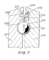
- Figure 7 shows a modification to the arrangement of Figure 4 which is advantageous when the brake is to be used in conjunction with a high speed shaft 203.
- the members 206, 207 are provided radially outwards of the balls 221, with respective chambers 230 opening into the cavity 212 lying between the membersd 206, 207.
- the chambers have ramp surfaces 234, respectively.
- a camming unit 233 of generally T-shape is arranged partially in the chambers 230 and partially in the cavity 212 so that the stem 232 of the "T” extends radially inwards between the members 206, 207 and has its terminal portion extending into the space between the two tear-shaped recesses 220.
- the head of the "T” of the unit 233 extends into the chambers 230 and is provided with two convergent ramp surfaces 231 which are complementary to the ramp surfaces 234 of the chambers 230.
- the balls 221 are forced outwardly by centrifugal forces with rotation of the members 206 and 207.
- the outward force of the balls 221 is substantial, and acts on the terminal portion of the stem 232 of the unit 233 to force its ramp surfaces 231 against the ramp surfaces 234 of the members 206, 207.
- This force dependent on the angle of the ramp surfaces, amongst other factors, acts to force the two members 206, 207 towards one another as the speed of rotation increases. In this way the generation of heat losses in the vicinity of the braking surfaces of the casing can be substantially reduced at high speeds of rotation, at times when the brake is not required to become effective.
- Figure 6 shows, diagrammatically, an arrangement of braking mechanism using only one pair of complementary braking surfaces.
- a casing 300 contains an output drive shaft 301 slackly splined to a disc member 302.
- a frust-conical braking surface 303 is provided on the rim of the member 302 and is complementary to a similarly shaped braking surface 304 provided inside the casing 300.
- the disc member 302 is arranged opposite a rotary plate 305 attached to one end of a drive shaft 306 and located inside a cavity 307 in the casing 300.
- a motor 310 drives the shaft 306.
- the plate 305 carries an abutment 311 which, with rotation of the plate 305 in one direction only, engages a stop 309 on the disc member 302 in a similar way to the arrangement referenced 140, 141 in Figure 3.
- a camming arrangement of balls and recesses similar to that referenced 142, 143, 150 in Figure 3, is also provided between the plate 305 and the disc member 302. The camming arrangement behaves similarly to vary the separation of the disc member 302 from the plate 305 in accordance with the direction of the applied torque.
- a spring (not shown) maintains a slight rubbing contact between the braking surfaces during normal operation of the mechanism.
- the disc member 302 Under normal operating of the mechanism of Figure 6, the disc member 302 is at its closest position to the plate 305 and the abutment on the plate engages the stop 309 so that the drive of the shaft 306 is transmitted through the disc member 302 to the output shaft 301.
Landscapes
- Engineering & Computer Science (AREA)
- General Engineering & Computer Science (AREA)
- Mechanical Engineering (AREA)
- Braking Arrangements (AREA)
Abstract
Description
- THIS INVENTION relates to a braking mechanism which responds automatically to a reversal in an applied torque by applying a brake. Such a mechanism may be used to protect a load from "running away" if a driving torque falls beneath a certain value, or for interrupting a transmission of drive between a motor and a load.
- An inclined travelling slat conveyor required to lift a distributed load between two levels can cause extensive damage if there is a failure of its operating motor. The loss of driving torque may cause the distributed load on the conveyor to take charge, and reverse the direction of movement of the conveyor. Unless precautions are taken to prevent it, the distributed load is then deposited at the lower end of the conveyor with serious consequences to equipment and personnel at the lower level.
- A similar problem is encountered in many other spheres of activity, where heavy loads are being moved, one such activity is the operation of a bucket elevator.
- In accordance with a first aspect of the invention a braking mechanism which becomes automatically effective when there is a reversal in the direction of torque, comprises two members having a common axis and between which relative rotation about the axis occurs when there is a reversal in the direction of the applied torque; a housing surrounding the two members; a first braking surface provided on one of the members and a second, complementary and opposed braking surface provided on the housing; first means operating to accommodate change in the spacing between the two members to control the extent of the braking; second means responsive to a reversal in torque direction to permit change in the relative angular positions of the members; camming means incorporating thrust-resistant means and responsive to the change in the relative angular positions of the members to alter the spacing between the members; and resilient means for biassing the braking surfaces towards one another to induce the required braking action promptly when the direction of torque is reversed.
- Preferably both members rotate and each is equipped with its own braking surface which engages a respective braking surface on the surrounding housing.
- Conveniently the camming means comprises pairs of recesses formed on opposed faces, respectively, of the members. The recesses are suitably arcuate about the common axis and each may be tear-shaped with the tapered ends of the tears of each pair of recesses extending respectively in opposite directions about the common axis. In such an arrangement the thrust-resistant means is suitably a hard ball. If the torque direction through the mechanism reverses, the angular displacement between the members causes the ball to force the members apart so that braking is increased.
- It is advisable to maintain at least some braking reaction between the braking surfaces under all conditions of operation. This may be achieved by the resilient biassing means which may be a compression spring or springs located between the two members.
- In an advantageous arrangement of the invention, part of the drive transmitted through the mechanism is used to operate a hydraulic pump providing a hydraulic cushion between the braking surfaces so that they are forced apart and the wear on them is minimised when the direction of the torque transmission through the mechanism is in the desired direction. If the torque is reversed, braking immediately occurs as the braking surfaces are forced against one another. A reduction in the speed of rotation of the members with respect to the housing then ensues, and the output pressure of the pump falls. This reduces the effectiveness of the hydraulic cushion between the braking surfaces which can therefore contact one another more forceably to enhance the braking effect.
- It is preferred for one of the two engaging braking surfaces always to be made from a softer material than the other braking surface.
- In accordance with a second aspect of the invention a braking mechanism which becomes automatically effective when there is a reversal in the direction of applied torque, includes two members turned by the applied torque about a common axis and providing at least one braking surface engageable with a complementary braking surface of a surrounding housing, the two members being angularly displaceable and relatively axially moveable with respect to one another and having camming means arcuate about their common axis and engaged by thrust-resistant means which allow relative rotation of the members to bring different parts of the camming means into engagement with the thrust-resistant means and so vary the spacing between the members, the profiles of the camming means being so chosen that relative rotation of one of the members in one direction of rotation with respect to the other and produced by a reversal in the applied torque, causes the spacing between the members to change and bring said one braking surface into braking engagement with the complementary braking surface of the housing. Preferably each of the members has a braking surface.
- In the preferred arrangement of the second aspect of the invention the two members comprise opposed spaced discs mounted slackly on a common shaft so as to permit them relative angular movement and axial movement, with respect to one another, while allowing both discs to be driven. The discs conveniently are provided on their remote faces with frusto-conical braking surfaces. If one disc turns with respect to the other in a direction which increases the effective axial thickness of the camming means between them, the two discs are thrust apart and braking ensues.
- In a version of the invention used in a supervisory role to protect a load driven directly by a prime-mover, the two members having eccentric abutment surfaces at the same radius from their common axis. Rotation of one of the members in one direction by the prime-mover causes the abutments to engage and transmit the rotational drive to the other member. In this situation the assembly of camming means and thrust-resistant means allows the members to assume positions at which braking is a minimum. If now the applied torque is reversed, the abutment surfaces move apart and different parts of the camming surfaces are now borne on by the thrust-resistant means. The two members are urged apart as a consequence, and braking ensues.
- Suitably, the second member is provided with a manually operable rotational drive which allows it to be turned gradually in the direction of reengagement of the abutment surfaces. The first member, under the action of the applied load torque, follows this movement. The load can thus be manually controlled in safety after the braking mechanism has operated.
- The invention will now be described in more detail by way of examples, with reference to the acompanying diagrammatic and schematic drawings in which:
- FIGURE 1 shows a braking mechanism in vertical section interposed in a drive transmission between a motor and a load;
- FIGURE 2 is a vertical section through figure 1 taken on the line and in the direction indicated by the arrows II - II in that figure;
- FIGURE 3 shows a second form of braking mechanism exercising a supervisory role over a direct drive transmission between a motor and a load;
- FIGURE 4 shows a braking mechanism in vertical section and incorporating an oil pump;
- FIGURE 5 is a perspective exploded view showing an arrangement of camming means and thrust-resistant means disposed between opposed faces of two members, used in the braking mechanism of figure 4;
- FIGURE 6 is a diagrammatic vertical section through a braking mechanism having one pair of opposed braking surfaces; and,
- FIGURE 7 shows, in enlarged section, a modification to the braking mechanism of Figure 4a and which is positioned radially outwards of respective balls to provide a speed-sensitive control for the braking mechanism.
- The mechanism of Figure 1 comprises a fixed casing 1 having aligned
bores 2 and 3 threaded byrespective shafts 4 and 5. Annular frusto-conical braking surfaces 6 and 7 are provided on opposite sides of acentral cavity 8 in the casing 1. - The shaft 4 carries outside the casing 1 a
load pinion 11, and inside the casing it has slideably splined to it a first frusto-conical member 12 of disc shape. Theshaft 5 is connected outside the casing to adrive motor 13, and inside the casing it is slackly keyed, as shown in figure 2, to a second frusto-conical member 14 also of disc shape. The twomembers respective braking surfaces braking surfaces 6 and 7 of the casing 1. Alight compression spring 19 provides a resilient bias which maintains themembers braking surfaces 6, 7. Theshaft 5 extends across thecavity 8 and has itsterminal portion 17 slackly keyed to thefirst member 12 in the manner shown in figure 2. Thus themembers shaft 5. - The opposed faces of the
member camming surfaces camming surface 21 projects from the face of themember 14, increases progressively around its arc. - In operation of the mechanism of figures 1 and 2, drive is transmitted from the
motor 13 to theload pinion 11 by way of the engagement of theshaft 5 with themember 12. Theshaft 5 also drives themember 14 at the same speed. The positioning of thecamming surfaces braking surfaces spring 19 provides a resilient reaction between themembers - If the direction of torque through the mechanism is reversed for any reason, the load pinion moves the
member 12 angularly with respect to themember 14, the slack keying on theshaft 5 permitting this angular movement. The effect of the angular movement is to bring different parts of thecamming surfaces members braking surfaces complementary braking surfaces 6, 7 of the casing. Braking of the load pinion then ensues. - In the arrangement shown in figure 3, parts corresponding in function to similar parts of figures 1 and 2, are correspondingly referenced but in the 'hundreds' series. Thus the casing 1 is referenced 101 in figure 3, and so forth. These parts will not be again described to avoid needless repetition of description.
- In the arrangement shown in figure 3 a direct drive transmission connection is established from the
motor 113 to aload pinion 111 by way of adrive pinion 130 fixed to theshaft 105. The load driven by thepinion 111 is an inclinedslat conveyor 131 having parallel belt runs equipped with slats which lift a distributed load between two levels. A dangerous situation can develop with such an arrangement if power is removed from themotor 113 as this enables the load on the conveyor to descend out of control, by back-driving the motor, with the serious risk of consequences to a loading station at the lower end of the conveyor. - This risk is avoided by continuing the
shaft 105 into a fixedcasing 101, and slackly keying amember 114 on to its end inside acavity 108 in a manner similar to that shown in figure 2. Themember 114 faces amember 112 and they are provided on their remote surface with frusto-conical braking surfaces 115, 116 positioned to be engageable withcomplementary braking surfaces casing 101. Themember 112 is slackly keyed to ashaft 134 which is coaxially arranged with respect to theshaft 105 and has a squarecross-section terminal portion 135 outside thecasing 101 to enable a manuallyoperable spanner 136 to be applied to it to turn themember 112. - The opposed faces of the
member abutment elements respective members motor 113 is driving in a direction which operates the conveyor in a load-lifting direction. The rotation of theshaft 105 is then transmitted to the twomembers - The second assembly comprises a pair of arcuate camming faces 150, 142 which engage opposite sides of thrust-
resistant balls 143 and are arcuate about the common axis of rotation of themembers camming face 142 and the supportingmember 114 increases progressively from one end of thearcuate camming face 142 to the other. A central, weak, coiled,compression spring 144 urges the opposed faces of themembers braking surfaces casing 101 to maintain a slight braking effect. - When the
motor 113 is driving theconveyor 131 in its lifting direction, the twomembers balls 143 are borne on by portions of the camming surfaces 150, 142, which enable themembers - If the direction of torque of the
shaft 105 is reversed in direction, caused by the load on theconveyor 131 back-driving themotor 113, themember 114 reverses its direction of rotation to cause theabutment elements balls 143 to engage different parts of the camming surfaces 142, 150. This has the effect of forcing the twomembers braking surfaces complementary braking surfaces casing 101. The greater the reverse torque exerted on theshaft 105 by the back-drive of theload conveyor 131, the greater the braking force exerted by the mechanism. Back-drive to the motor is thus prevented and the static load on the conveyor is held by the braking force of the mechanism. - By applying the
spanner 136 to theend 135 of theshaft 134 while the load is braked to a stationary position by the mechanism, themember 112 can be manually turned in a direction corresponding to the descent of the load on the conveyor. The manual rotation of themember 112 is progressively followed by the rotation of themember 114 under the influence of the load on the conveyor. In this way the conveyor can be lowered gradually under total manual control, until the distributed load on it has been removed. Themotor 113 can then be re-started. - Figure 4 shows a
bucket conveyor 200 driven by adrive shaft 201 of amotor 202. Thedrive shaft 201 is extended at 203 to abraking mechanism 204 designed to prevent torque reversal of thedrive shaft 201. - The
mechanism 204 comprises acasing 205 containing tworotary disc members conical rims 208, 209 respectively equipped with braking surfaces (not shown) of any known type. Thedisc member 206 is slideably splined at 299 to theshaft 203 as depicted by the key 299, and thedisc member 207 is slideably splined in similar manner to asecond shaft 210 arranged coaxially with respect to theshaft 203. The twoshafts - The two
disc members compression springs 211 so that their frusto-conical braking surfaces engage complementary frusto-conical braking surfaces of the casing provided inside acavity 212 in which the disc members rotate. The casing braking surfaces are made of a harder material than those of thedisc members - The opposed faces of the
disc members annular channel 213 leading into asump 214 in thecasing 205. Oil is withdrawn from thesump 214 by way of apassage 215 leading to agear pump 216 inside the casing and driven by theshaft 210. Thegear pump 216 supplies oil under pressure throughducts 217 to provide hydraulic lubricating cushions of oil between the opposed braking surfaces of the disc members and the casing. These hydraulic cushions lessen the extent of frictional braking occurring between the braking surfaces, as compared with the frictional braking which would otherwise occur by virtue of the compression of thesprings 211. - The opposed faces of the
disc members recesses 220 as shown in Figure 5. The two rings ofrecesses 220 are arranged at the same radius and opposite one another, and they are identical. However the tear-drop recesses of one ring point in the opposite direction around the ring to the tear-drop recesses of the other ring. Each pair of opposed recesses accommodates ahard steel ball 221. Theballs 221 are each acted upon by the camming effect of their associated recesses so that they control the spacing between thedisc members - One end of the
shaft 210 projects out of thecasing 205 and itsterminal portion 225 is of square cross-section to receive aspanner 224. - The mechanism of Figures 4 and 5 operates as follows:
- During normal operation of the
bucket elevator 200, themotor 202 is delivering torque to it and also driving theshaft 203. This causes thedisc member 206 to turn in a direction causing theballs 221 to occupy the positions in therecesses 220 denoted in broken outline in Figure 4. Drive is transmitted via theballs 221 to thedisc member 207. This causes rotation of theshaft 210 and thegear pump 216 to circulate oil through theducts 217. An oil cushion is thus created between the opposed frusto-conical braking surfaces of thedisc members casing 205, so that, despite the compression of thesprings 211, the energy loss through braking is small as the oil cushion ensures minimal frictional contact between the braking surfaces. - If now the
motor 202 fails, theshaft 201 is turned by thebucket elevator 200 in the reverse direction. The ramp surfaces of the tear-drop recesses 220 of thedisc member 206 engage theballs 221 causing them to force the opposed faces of thedisc members disc member 207 caused by the movement ofdisc member 206, causes the output pressure of thegear pump 216 to reduce. The oil cushion between the braking surfaces collapses to allow thesprings 211 to increase the reaction at the braking surfaces. Bothmembers - The
mechanism 204 remains effective to hold thebucket elevator 200 in a braked state until themotor 202 starts once again. If it is required to lower the bucket elevator progressively, under complete manual control, thehandle 224 is applied to theterminal portion 225 of theshaft 210 and turned in a direction to bring the deepest parts of therecesses 220 opposite one another. This reduces the spacing between thedisc members disc member 206 to follow the manual turning movement of thedisc member 207. This allows theshaft 203 to turn gradually and thus the load can be lowered under the complete control of thehandle 224. - Figure 7 shows a modification to the arrangement of Figure 4 which is advantageous when the brake is to be used in conjunction with a
high speed shaft 203. - The
members balls 221, withrespective chambers 230 opening into thecavity 212 lying between the membersd 206, 207. The chambers haveramp surfaces 234, respectively. - A
camming unit 233 of generally T-shape is arranged partially in thechambers 230 and partially in thecavity 212 so that thestem 232 of the "T" extends radially inwards between themembers recesses 220. The head of the "T" of theunit 233 extends into thechambers 230 and is provided with two convergent ramp surfaces 231 which are complementary to the ramp surfaces 234 of thechambers 230. - In operation of the embodiment of Figure 7, the
balls 221 are forced outwardly by centrifugal forces with rotation of themembers balls 221 is substantial, and acts on the terminal portion of thestem 232 of theunit 233 to force its ramp surfaces 231 against the ramp surfaces 234 of themembers members - When braking is required, its operation is achieved as has already been described with reference to Figure 4.
- The arrangement of braking mechanism as shown in Figure 4 has enabled the mechanism to be used with drive speed in the region of 1000rpm, and by using the modification of Figure 7 it is believed that rotational speeds as high as 1400rpm can be handled without incurring excessive frictional heat losses.
- Figure 6 shows, diagrammatically, an arrangement of braking mechanism using only one pair of complementary braking surfaces. In this figure, a
casing 300 contains anoutput drive shaft 301 slackly splined to adisc member 302. A frust-conical braking surface 303 is provided on the rim of themember 302 and is complementary to a similarly shapedbraking surface 304 provided inside thecasing 300. - The
disc member 302 is arranged opposite arotary plate 305 attached to one end of adrive shaft 306 and located inside acavity 307 in thecasing 300. Amotor 310 drives theshaft 306. - The
plate 305 carries an abutment 311 which, with rotation of theplate 305 in one direction only, engages astop 309 on thedisc member 302 in a similar way to the arrangement referenced 140, 141 in Figure 3. A camming arrangement of balls and recesses, similar to that referenced 142, 143, 150 in Figure 3, is also provided between theplate 305 and thedisc member 302. The camming arrangement behaves similarly to vary the separation of thedisc member 302 from theplate 305 in accordance with the direction of the applied torque. A spring (not shown) maintains a slight rubbing contact between the braking surfaces during normal operation of the mechanism. - Under normal operating of the mechanism of Figure 6, the
disc member 302 is at its closest position to theplate 305 and the abutment on the plate engages thestop 309 so that the drive of theshaft 306 is transmitted through thedisc member 302 to theoutput shaft 301. - If the direction of the torque transmission through the mechanism reverses, the
stop 309 moves away from the abutment of theplate 305 and thecamming arrangement 308 becomes effective, as has been described with reference to Figure 3, to force thedisc member 302 away from theplate 305. This brings the braking surfaces 303, 304 into forceable braking engagement with one another so that rotation of theshaft 301 is braked until the direction of applied torque is restored.
Claims (7)
- A braking mechanism which becomes automatically effective when there is a reversal in the direction of torque, comprising: two members (12, 14; 112, 114; 206, 207; 302, 305;) having a common axis and between which relative rotation about the axis occurs when there is reversal in the direction of the applied torque; a housing (1, 101, 205, 300) surrounding the two members; a first braking surface (15, 16; 115, 116; 303, 304) provided on one of the members and a second complementary and opposed braking surface (6, 7; 106, 107; 208, 209; 304) provided on the housing; first means (axial splins 299) accommodating change in the spacing between the two members to control the extent of the braking; second means (slackness of spline) responsive to a reversal in torque direction to permit change in the relative angular positions of the members; CHARACTERISED BY the provision of camming means (20, 21; 142, 150; 220) incorporating thrust-resistant means (22, 143, 221, 308) and responsive to the change in the relative angular positions of the members, to alter the spacing between the members; and, resilient means (19, 144, 211 ) for biassing the braking surfaces towards one another to induce the required braking action promptly when the direction of torque is reversed.
- A mechanism as claimed in Claim 1, CHARACTERISED IN THAT both members rotate and each is provided with its own braking surface (15, 16; 115, 116; 303) for engaging a respective braking surface (6, 7; 106, 107; 208, 209; 304) provided inside the surrounding housing.
- A mechanism as claimed in Claim 1 or Claim 2, CHARACTERISED BY the camming means including pairs of recesses (220), the recesses of each pair being formed, respectively, on opposed faces of the members and being of tear-drop shape; a htrust-resistant ball (212) being accommodated between the recesses of each pair for transmitting drive between the two members when the torque is not reversed, and for forcing the two members apart when the torque is reversed, to induce braking.
- A mechanism as claimed in Claim 1 or 2, CHARACTERISED IN THAT the complementary braking surfaces of the housing and of the members are of different hardness, respectively.
- A mechanism as claimed in Claim 1 or 2, CHARACTERISED BY the housing a hydraulic pump (216) operated by drive from one of the members (207) which is to be braked, and hydraulic ducts (217) leading from the output side of the pump to the vicinity of the complementary braking surfaces (208, 209) of the members and the housing to create a hydraulic cushion between them when the direction of torque through the mechanism is not reversed, the drive to the hydraulic pump diminishing, during braking, to collapse the cushion and permit prompt braking of the mechanism.
- A mechanism as claimed in Claim 1 or 2, CHARACTERISED BY it including centrifugally operated means (221; 232; 233; 234) which bias the braking surfaces apart at relatively high rotational speeds, and reduce the bias as the speed diminishes.
- A mechanism as claimed in Claim 1 or 2, CHARACTERISED BY the provision of a handle (136, 234) allowing one of the members (112, 207) to be manually rotated with respect to the other (114, 206) in the direction of the load (131, 200), so that the other member can follow the manual rotation and allow the load to be moved, under complete control, in the direction of the reversed torque.
Applications Claiming Priority (2)
| Application Number | Priority Date | Filing Date | Title |
|---|---|---|---|
| AU171/90 | 1990-05-16 | ||
| AUPK017190 | 1990-05-16 |
Publications (2)
| Publication Number | Publication Date |
|---|---|
| EP0457475A2 true EP0457475A2 (en) | 1991-11-21 |
| EP0457475A3 EP0457475A3 (en) | 1993-06-09 |
Family
ID=3774683
Family Applications (1)
| Application Number | Title | Priority Date | Filing Date |
|---|---|---|---|
| EP19910304106 Withdrawn EP0457475A3 (en) | 1990-05-16 | 1991-05-07 | Braking mechanism |
Country Status (6)
| Country | Link |
|---|---|
| US (1) | US5090529A (en) |
| EP (1) | EP0457475A3 (en) |
| JP (1) | JPH04228934A (en) |
| CN (1) | CN1064061A (en) |
| CA (1) | CA2041770A1 (en) |
| ZA (1) | ZA913408B (en) |
Cited By (3)
| Publication number | Priority date | Publication date | Assignee | Title |
|---|---|---|---|---|
| WO1999058869A1 (en) * | 1998-05-12 | 1999-11-18 | Weatherford/Lamb, Inc. | Centrifugal backspin retarder and drive head for use therewith |
| WO2001094244A1 (en) * | 2000-06-07 | 2001-12-13 | Van Der Graaf Inc. | Releasable backstop for conveyor rollers |
| CN112088138A (en) * | 2018-05-14 | 2020-12-15 | 三菱电机株式会社 | Safety device for elevator and safety system for elevator |
Families Citing this family (25)
| Publication number | Priority date | Publication date | Assignee | Title |
|---|---|---|---|---|
| AU650555B2 (en) * | 1991-08-15 | 1994-06-23 | Ivg Australia Pty. Ltd. | Rotation check mechanism |
| US5299676A (en) * | 1991-08-15 | 1994-04-05 | Ivg Australia Pty. Limited | Rotation check mechanism |
| US5735514A (en) * | 1996-09-03 | 1998-04-07 | Chick Machine Tool, Inc. | Indexing apparatus |
| CA2311036A1 (en) * | 2000-06-09 | 2001-12-09 | Oil Lift Technology Inc. | Pump drive head with leak-free stuffing box, centrifugal brake and polish rod locking clamp |
| DE10214419A1 (en) * | 2002-03-30 | 2003-10-30 | Ennepetaler Schneid Maehtech | Tool with at least one tool that can be driven by a motor and a brake that stops the tool |
| US6666307B1 (en) * | 2002-08-05 | 2003-12-23 | Honeywell International, Inc. | Thrust reverser system with a pass-through torque activated brake |
| WO2006069442A1 (en) * | 2004-12-27 | 2006-07-06 | Louis Morissette | Braking mechanism for moving assemblies |
| US8109494B1 (en) | 2006-09-01 | 2012-02-07 | Chick Workholding Solutions, Inc. | Workholding apparatus having a movable jaw member |
| US8336867B1 (en) | 2006-09-01 | 2012-12-25 | Chick Workholding Solutions, Inc. | Workholding apparatus having a detachable jaw plate |
| US8573578B1 (en) | 2006-09-01 | 2013-11-05 | Chick Workholding Solutions, Inc. | Workholding apparatus |
| US8454004B1 (en) | 2006-09-01 | 2013-06-04 | Chick Workholding Solutions, Inc. | Workholding apparatus having a movable jaw member |
| US9227303B1 (en) | 2006-09-01 | 2016-01-05 | Chick Workholding Solutions, Inc. | Workholding apparatus |
| US8511441B2 (en) * | 2010-04-01 | 2013-08-20 | Hamilton Sundstrand Corporation | Cone brake no-back |
| TW201348012A (en) * | 2012-05-25 | 2013-12-01 | Hon Hai Prec Ind Co Ltd | Transmission control apparatus and transmission apparatus having same |
| US9352451B1 (en) | 2013-05-02 | 2016-05-31 | Chick Workholding Solutions, Inc. | Workholding apparatus |
| CN103322095B (en) * | 2013-06-27 | 2016-04-27 | 恩博沃克(北京)科技发展有限公司 | Pumping unit One-touch smart brake device |
| US9616990B2 (en) | 2014-07-18 | 2017-04-11 | Hamilton Sundstrand Corporation | Aircraft component rotary device |
| US9527580B2 (en) | 2014-09-24 | 2016-12-27 | Hamilton Sundstrand Corporation | Cone brake no-back assembly with gain reduction spring and method |
| CN106882539B (en) * | 2017-03-27 | 2024-04-16 | 重庆市巫山城市建设(集团)有限公司 | Feeding mechanism of rosewood skin cutting machine |
| CN108840204B (en) * | 2018-08-04 | 2023-09-19 | 安徽理工大学 | An energy recovery component during braking of a mine hoist |
| CN108910647B (en) * | 2018-08-21 | 2020-05-12 | 日立电梯(中国)有限公司 | An elevator balance rescue device |
| CN109052099B (en) * | 2018-10-08 | 2023-08-22 | 张家港市荣达建筑机械制造有限公司 | A backrest roller used for racks of construction lifts |
| CN114132716B (en) * | 2021-12-03 | 2024-03-08 | 福建龙净环保股份有限公司 | Pipe belt machine and broken belt capturing device thereof |
| CN115258996B (en) * | 2022-06-20 | 2023-06-02 | 浙江机电职业技术学院 | Embedded intelligent winch brake device |
| CN115947063B (en) * | 2023-02-06 | 2023-10-03 | 承德古德卡威尔自动化科技有限公司 | Synchronous control system for stay cord coding of tensioning part of double-drive conveyor |
Family Cites Families (18)
| Publication number | Priority date | Publication date | Assignee | Title |
|---|---|---|---|---|
| US710757A (en) * | 1900-10-23 | 1902-10-07 | Edgar P Coleman | Mechanical brake for hoisting machinery. |
| US710758A (en) * | 1900-10-23 | 1902-10-07 | Edgar P Coleman | Mechanical brake. |
| US1614629A (en) * | 1925-07-28 | 1927-01-18 | Quick William | Window-control device |
| US2675898A (en) * | 1950-09-12 | 1954-04-20 | Connecticut Variable Gear Corp | Unidirectional drive coupling |
| US2783861A (en) * | 1954-11-29 | 1957-03-05 | Cleveland Pneumatic Tool Co | Drive-released brake |
| NL114053C (en) * | 1961-06-09 | 1968-08-15 | Hunter Douglas International | SELF-BRAKE DRIVE FOR A BLIND, ROLLER SHUTTER OR SIMILAR SCREEN |
| US3384708A (en) | 1965-08-23 | 1968-05-21 | Mvr Corp | Video preproducer switching and signal processing system |
| US3536169A (en) * | 1969-01-10 | 1970-10-27 | Carter H Arnold | Load brake for unidirectional or bidirectional use |
| US3584708A (en) * | 1969-06-02 | 1971-06-15 | Gen Motors Corp | Sealed liquid cooled brake assembly |
| GB1341707A (en) * | 1970-06-02 | 1973-12-25 | Rotax Ltd | Drive mechanisms |
| US3797614A (en) * | 1971-09-02 | 1974-03-19 | Envirotech Corp | Automatic unidirectional brake |
| US4280605A (en) * | 1979-08-02 | 1981-07-28 | George Papadopoulos | Automatically locking brake assembly |
| CH645702A5 (en) * | 1982-01-29 | 1984-10-15 | Fasa Fonderie Et Ateliers Meca | Emergency brake for braking a shaft |
| DE3603307A1 (en) * | 1986-02-04 | 1987-08-06 | Rhein Getriebe Gmbh | Load-moment lock |
| US4909363A (en) * | 1987-06-15 | 1990-03-20 | Sundstrand Corporation | Unidirectional no-back device |
| US4842109A (en) * | 1987-12-22 | 1989-06-27 | Sundstand Corp. | Bidirectional drive with a unidirectional irreversibility mechanism |
| US4860869A (en) * | 1988-07-18 | 1989-08-29 | General Motors Corporation | Brake apply system with a differential mechanism |
| US4850458A (en) * | 1988-11-16 | 1989-07-25 | Boeing Company | Bidirectional rotary brake |
-
1990
- 1990-09-28 US US07/590,292 patent/US5090529A/en not_active Expired - Fee Related
-
1991
- 1991-05-03 CA CA002041770A patent/CA2041770A1/en not_active Abandoned
- 1991-05-06 ZA ZA913408A patent/ZA913408B/en unknown
- 1991-05-07 EP EP19910304106 patent/EP0457475A3/en not_active Withdrawn
- 1991-05-09 CN CN91103024A patent/CN1064061A/en active Pending
- 1991-05-15 JP JP3139620A patent/JPH04228934A/en active Pending
Cited By (7)
| Publication number | Priority date | Publication date | Assignee | Title |
|---|---|---|---|---|
| WO1999058869A1 (en) * | 1998-05-12 | 1999-11-18 | Weatherford/Lamb, Inc. | Centrifugal backspin retarder and drive head for use therewith |
| US6079489A (en) * | 1998-05-12 | 2000-06-27 | Weatherford Holding U.S., Inc. | Centrifugal backspin retarder and drivehead for use therewith |
| GB2354298A (en) * | 1998-05-12 | 2001-03-21 | Weatherford Canada Ltd | Centrifugal backspin retarder and drive head for use therewith |
| GB2354298B (en) * | 1998-05-12 | 2002-12-04 | Weatherford Canada Ltd | Centrifugal backspin retarder |
| WO2001094244A1 (en) * | 2000-06-07 | 2001-12-13 | Van Der Graaf Inc. | Releasable backstop for conveyor rollers |
| US6766900B2 (en) | 2000-06-07 | 2004-07-27 | Van Der Graaf Inc. | Releasable backstop for conveyor rollers |
| CN112088138A (en) * | 2018-05-14 | 2020-12-15 | 三菱电机株式会社 | Safety device for elevator and safety system for elevator |
Also Published As
| Publication number | Publication date |
|---|---|
| EP0457475A3 (en) | 1993-06-09 |
| JPH04228934A (en) | 1992-08-18 |
| ZA913408B (en) | 1992-03-25 |
| US5090529A (en) | 1992-02-25 |
| CN1064061A (en) | 1992-09-02 |
| CA2041770A1 (en) | 1991-11-17 |
Similar Documents
| Publication | Publication Date | Title |
|---|---|---|
| US5090529A (en) | Brake mechanism | |
| US6079489A (en) | Centrifugal backspin retarder and drivehead for use therewith | |
| US4548316A (en) | Run-back safety mechanism for conveyor apparatus | |
| US4005895A (en) | Rotational grapple | |
| US5127631A (en) | Chain hoist with integral safety device | |
| EP0528638A1 (en) | Rotation check mechanism | |
| US4075873A (en) | Free-wheeling overload coupling | |
| US2496201A (en) | Speed responsive clutch mechanism | |
| US3285377A (en) | Torque released one way brake | |
| EP0037404B1 (en) | Automatically resetting safety brake | |
| EA014039B1 (en) | Cam-actuated centrifugal brake for preventing backspin | |
| US6772863B2 (en) | Brake appliance for gerotor motors | |
| US6874606B1 (en) | Torque limiting clutch having centrifugally regulated characteristic torque | |
| US3038576A (en) | Torque limiting and overload sensing device | |
| JPH0525800B2 (en) | ||
| US11691848B2 (en) | Safely brake for an elevator | |
| EP0189246B1 (en) | Bearing fail-safe device | |
| JPH0755792B2 (en) | Emergency lowering speed control device for lifting device | |
| US3603561A (en) | Anchor windlass for a marine vessel | |
| US20050133774A1 (en) | Drive-through force transmission device and methods | |
| KR200243892Y1 (en) | Brake apparatus for elevator | |
| EP0875448A2 (en) | Braking device, particularly for braking the descent of a life-boat | |
| EP0331362B1 (en) | Drive engagement delay device | |
| GB2275745A (en) | Torque overload limiter | |
| AU650555B2 (en) | Rotation check mechanism |
Legal Events
| Date | Code | Title | Description |
|---|---|---|---|
| PUAI | Public reference made under article 153(3) epc to a published international application that has entered the european phase |
Free format text: ORIGINAL CODE: 0009012 |
|
| AK | Designated contracting states |
Kind code of ref document: A2 Designated state(s): AT BE CH DE DK ES FR GB GR IT LI LU NL SE |
|
| PUAL | Search report despatched |
Free format text: ORIGINAL CODE: 0009013 |
|
| AK | Designated contracting states |
Kind code of ref document: A3 Designated state(s): AT BE CH DE DK ES FR GB GR IT LI LU NL SE |
|
| 17P | Request for examination filed |
Effective date: 19931208 |
|
| 17Q | First examination report despatched |
Effective date: 19940627 |
|
| STAA | Information on the status of an ep patent application or granted ep patent |
Free format text: STATUS: THE APPLICATION IS DEEMED TO BE WITHDRAWN |
|
| 18D | Application deemed to be withdrawn |
Effective date: 19941108 |