EP0457507A1 - Disques pour le fractionnement par atomisation et méthode les utilisant - Google Patents
Disques pour le fractionnement par atomisation et méthode les utilisant Download PDFInfo
- Publication number
- EP0457507A1 EP0457507A1 EP91304203A EP91304203A EP0457507A1 EP 0457507 A1 EP0457507 A1 EP 0457507A1 EP 91304203 A EP91304203 A EP 91304203A EP 91304203 A EP91304203 A EP 91304203A EP 0457507 A1 EP0457507 A1 EP 0457507A1
- Authority
- EP
- European Patent Office
- Prior art keywords
- disk
- trip
- skirt
- edge
- wall
- Prior art date
- Legal status (The legal status is an assumption and is not a legal conclusion. Google has not performed a legal analysis and makes no representation as to the accuracy of the status listed.)
- Withdrawn
Links
- 238000005194 fractionation Methods 0.000 title claims abstract description 54
- 239000007921 spray Substances 0.000 title claims description 8
- 238000000034 method Methods 0.000 title claims description 6
- 239000002245 particle Substances 0.000 claims abstract description 57
- 239000002002 slurry Substances 0.000 claims abstract description 50
- 239000007788 liquid Substances 0.000 claims abstract description 31
- 239000000725 suspension Substances 0.000 claims abstract description 10
- 230000002093 peripheral effect Effects 0.000 claims description 19
- 239000000463 material Substances 0.000 claims description 7
- 239000000203 mixture Substances 0.000 claims description 7
- 239000006194 liquid suspension Substances 0.000 claims 2
- 229920001131 Pulp (paper) Polymers 0.000 abstract description 3
- 239000000835 fiber Substances 0.000 description 130
- 238000000926 separation method Methods 0.000 description 17
- 230000005012 migration Effects 0.000 description 14
- 238000013508 migration Methods 0.000 description 14
- 238000012360 testing method Methods 0.000 description 10
- XLYOFNOQVPJJNP-UHFFFAOYSA-N water Substances O XLYOFNOQVPJJNP-UHFFFAOYSA-N 0.000 description 7
- 238000013461 design Methods 0.000 description 6
- 230000000694 effects Effects 0.000 description 6
- 229920000297 Rayon Polymers 0.000 description 4
- 239000012530 fluid Substances 0.000 description 4
- 229920001343 polytetrafluoroethylene Polymers 0.000 description 4
- 239000002964 rayon Substances 0.000 description 4
- 239000007787 solid Substances 0.000 description 4
- 230000003749 cleanliness Effects 0.000 description 3
- 239000004744 fabric Substances 0.000 description 3
- 239000000123 paper Substances 0.000 description 3
- 239000004810 polytetrafluoroethylene Substances 0.000 description 3
- 239000013055 pulp slurry Substances 0.000 description 3
- 239000002356 single layer Substances 0.000 description 3
- 235000013351 cheese Nutrition 0.000 description 2
- 239000011362 coarse particle Substances 0.000 description 2
- 230000002209 hydrophobic effect Effects 0.000 description 2
- 239000010410 layer Substances 0.000 description 2
- -1 polytetrafluoroethylene Polymers 0.000 description 2
- 230000008569 process Effects 0.000 description 2
- 230000000452 restraining effect Effects 0.000 description 2
- 229910000831 Steel Inorganic materials 0.000 description 1
- 229920002522 Wood fibre Polymers 0.000 description 1
- 230000001133 acceleration Effects 0.000 description 1
- 230000009471 action Effects 0.000 description 1
- 239000004411 aluminium Substances 0.000 description 1
- 229910052782 aluminium Inorganic materials 0.000 description 1
- XAGFODPZIPBFFR-UHFFFAOYSA-N aluminium Chemical compound [Al] XAGFODPZIPBFFR-UHFFFAOYSA-N 0.000 description 1
- 230000003190 augmentative effect Effects 0.000 description 1
- 239000000356 contaminant Substances 0.000 description 1
- 239000011096 corrugated fiberboard Substances 0.000 description 1
- 230000003247 decreasing effect Effects 0.000 description 1
- 230000006866 deterioration Effects 0.000 description 1
- 230000001627 detrimental effect Effects 0.000 description 1
- 238000009826 distribution Methods 0.000 description 1
- 238000002474 experimental method Methods 0.000 description 1
- 239000010419 fine particle Substances 0.000 description 1
- 239000011121 hardwood Substances 0.000 description 1
- 230000006872 improvement Effects 0.000 description 1
- 238000004519 manufacturing process Methods 0.000 description 1
- 238000005259 measurement Methods 0.000 description 1
- 230000007246 mechanism Effects 0.000 description 1
- 229910052751 metal Inorganic materials 0.000 description 1
- 239000002184 metal Substances 0.000 description 1
- 239000010893 paper waste Substances 0.000 description 1
- 239000011087 paperboard Substances 0.000 description 1
- 239000004576 sand Substances 0.000 description 1
- 239000011122 softwood Substances 0.000 description 1
- 239000012798 spherical particle Substances 0.000 description 1
- 238000009987 spinning Methods 0.000 description 1
- 239000010959 steel Substances 0.000 description 1
- 230000007306 turnover Effects 0.000 description 1
- 238000011144 upstream manufacturing Methods 0.000 description 1
- 230000000007 visual effect Effects 0.000 description 1
- 239000002699 waste material Substances 0.000 description 1
- 238000009736 wetting Methods 0.000 description 1
- 239000002025 wood fiber Substances 0.000 description 1
Images




Classifications
-
- D—TEXTILES; PAPER
- D21—PAPER-MAKING; PRODUCTION OF CELLULOSE
- D21D—TREATMENT OF THE MATERIALS BEFORE PASSING TO THE PAPER-MAKING MACHINE
- D21D5/00—Purification of the pulp suspension by mechanical means; Apparatus therefor
- D21D5/18—Purification of the pulp suspension by mechanical means; Apparatus therefor with the aid of centrifugal force
- D21D5/22—Purification of the pulp suspension by mechanical means; Apparatus therefor with the aid of centrifugal force in apparatus with a vertical axis
-
- B—PERFORMING OPERATIONS; TRANSPORTING
- B03—SEPARATION OF SOLID MATERIALS USING LIQUIDS OR USING PNEUMATIC TABLES OR JIGS; MAGNETIC OR ELECTROSTATIC SEPARATION OF SOLID MATERIALS FROM SOLID MATERIALS OR FLUIDS; SEPARATION BY HIGH-VOLTAGE ELECTRIC FIELDS
- B03B—SEPARATING SOLID MATERIALS USING LIQUIDS OR USING PNEUMATIC TABLES OR JIGS
- B03B5/00—Washing granular, powdered or lumpy materials; Wet separating
-
- B—PERFORMING OPERATIONS; TRANSPORTING
- B03—SEPARATION OF SOLID MATERIALS USING LIQUIDS OR USING PNEUMATIC TABLES OR JIGS; MAGNETIC OR ELECTROSTATIC SEPARATION OF SOLID MATERIALS FROM SOLID MATERIALS OR FLUIDS; SEPARATION BY HIGH-VOLTAGE ELECTRIC FIELDS
- B03B—SEPARATING SOLID MATERIALS USING LIQUIDS OR USING PNEUMATIC TABLES OR JIGS
- B03B5/00—Washing granular, powdered or lumpy materials; Wet separating
- B03B5/68—Washing granular, powdered or lumpy materials; Wet separating by water impulse
- B03B5/70—Washing granular, powdered or lumpy materials; Wet separating by water impulse on tables or strakes
- B03B5/72—Washing granular, powdered or lumpy materials; Wet separating by water impulse on tables or strakes which are movable
- B03B5/74—Revolving tables
Definitions
- This invention relates generally to the field of apparatus and techniques for separating particles within a liquid carrier, such as fibers in a pulp slurry, according to the relative sizes and other characteristics of the particles, and relates particularly to fractionation disks for such apparatus.
- Processes for separating small particles contained in a suspension or slurry by size, wettability and other characteristics find application in various industries.
- the ability to make such separations is particularly desirable in paper making since the thickness and length of the pulp fibers are strongly related to the quality and characteristics of the paper produced from the fibers.
- Several specific potential uses in the paper industry for efficient fractionation processes have been identified.
- a pulp slurry formed of reclaimed waste paper or paper board may be fractionated to remove clumps and particulate contaminants, and to separate fibers above and below a desired size. For example, such fractionation would allow the "linerboard" fibers in a slurry of waste corrugated fiberboard to be separated from the "medium fibers.”
- Linerboard is mainly composed of softwood fibers of relatively large size (40-50 microns diameter, 3-5 mm length) whereas medium fibers are mainly hardwood fibers of smaller size (20-30 microns diameter, 1-3 mm length).
- Fractionation also would allow a single fiber source, which ordinarily is a mix of fibers of various sizes, to be used optimally in the production of a desired multi-layered product.
- Each fraction, separated by fiber size, could be used to form a single layer which would have characteristics reflecting the size of the fibers in the layer.
- the layers of different fractions would then be combined to form a multi-layered product with qualities not possessed by a single layer product formed from the original fiber mix.
- the separated pulp fractions also could be used alone to make single layer products having desired characteristics related to fiber size.
- some papermaking machines operate most efficiently with pulp having a particular fiber size range.
- Another potential application of pulp fractionation is the separation of a pulp stream into two or more fractions which can be beaten separately under optimium conditions and then recombined.
- the fractionation apparatus disclosed in U.S. Patent No. 4,427,541, the disclosure of which is incorporated herein by reference, has been shown to be highly effective in fractionating a slurry of fibers of varying diameter.
- This apparatus comprises a disk which is symmetrical about an axis of rotation with a face adapted to stabilize the film of the slurry deposited on the face, which terminates in a sharp, circular peripheral face edge.
- a descending rim or skirt extends from the face edge and terminates in a peripheral edge.
- a separator wall may be positioned adjacent the rim to separate physically the two fractions of spray ejected from the disk, one carrying the coarse particles and the other the fines.
- the chief limitation on the flow capacity of such an apparatus for fractionating a particle slurry is the extent to which the film stability can be maintained on the surface of the disk and break-up of the film prevented.
- the fractionation disk preferably has disk body with a planar floor and an inclined inner wall which extends upwardly from the perimeter of the floor and terminates in a sharp, axially symmetric lower trip edge.
- An axially symmetric trip extends from the trip edge and has a substantially outwardly extending portion and an inclined vertical portion which terminates in a sharp upper trip edge.
- a skirt extends outwardly, and is preferably inclined upwardly, from the upper edge of the trip and terminates at a peripheral edge.
- a substantially vertical rim descends from the edge of the skirt.
- the floor, wall, trip, and skirt of the disk are wettable and adapted to allow a stable film of the liquid carrying the particles to form thereon.
- Such discrimination in particle size allows separation of fibers by length, if fiber length is directly related to fiber diameter, as is generally the case for wood pulp.
- clumps of large fibers, shives, and relatively large foreign particles, such as sand, and particles less wettable than pulp fibers are substantially separated from the fine particles in such wood pulp slurries.
- the rotating disk has a trip with an outwardly extending trip width of about 1/32 inch and an inclined trip length of less than the maximum fiber migration distance.
- the skirt is preferably inclined upwardly at an angle of about 5 degrees.
- the shallow bowl-like disk surface permits a film of greater thickness to be formed thereon than on a disk in accordance with the prior art.
- the efficiency of a fractionation disk will fall off dramatically when the diameter of the particles to be fractionated is greater than the thickness of the slurry film on the disk.
- the bowl-like disk can permit effective fractionation of larger diameter fibers than was previously practical.
- the trip or trips serve to keep the fibers away from the wall in the area near the intersection of the wall and skirt, thus minimizing loss of the fiber velocity due to friction between the wall and the fiber. A greater proportion of the larger fibers will thus attain ejection velocity at the edge where the skirt begins, thereby improving fractionation efficiency over a disk which does not have a trip.
- Fig. 1 is a simplified cross-sectional view of a spray collector chamber enclosure with a rotating fractionation disk mounted therein illustratively showing streams of particles and liquids being collected.
- Fig. 2 is a radial cross-sectional view of a portion of a rotating disk illustratively showing the liquid film formed on the disk and the ejected particles.
- Fig. 3 is a radial cross section of an embodiment of a disk having a single trip.
- Fig. 4 is a more detailed view of a particular sized trip for a disk of the type of Fig. 2 schematically showing the fluid flow when the slurry is applied to the rotating disk.
- Fig. 5 is a schematic view of a particular sized trip for a disk of the type of Fig. 2 illustratively showing the alignment of particles in the film slurry when the disk is rotated.
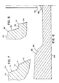
- Fig. 6 is a radial cross-sectional view of an embodiment of a disk having two trips.
- Fig. 7 is a cross-sectional view of a portion of a disk showing an alternative trip configuration.
- Fig. 8 is a cross-sectional view of a portion of a disk showing a further alternative trip configuration.
- Fig. 9 is an illustrative view of a typical collection pattern for fractionated fibers on cloth located 5 cm from the disk periphery.
- Figs. 10(a-d) are schematic illustrations of the qualitative ratings of separation and cleanliness for the separations described in certain of the examples.
- Fig. 11 is a radial cross-sectional view of another embodiment of a disk without a trip.
- FIG. 1 a simplified sectional view of fractionation apparatus in accordance with the invention is shown generally at 20 in Fig. 1.
- a generally cylindrical outer enclosure wall 21 and a top enclosure wall 22 surround and close off from the atmosphere a shallow bowl-type fractionation disk 24 having a solid, preferably metal body which is mounted for rotation about a vertical axis on a shaft 25 driven by an electric motor 26.
- the disk 24 is formed of a preferably solid body and is symmetric about the axis on which is rotates (the "axis of rotation").
- a truncated cone shaped separator wall 27 is mounted within the collector defined by the outer wall 21 and the inner wall 30 to separate the collector into two chambers.
- a first chamber or sump defined between the separator wall 27 and the conical inner wall 30, collects the smaller fibers along with most of the water.
- the water and fiber slurry collected in the sump is drained out through sump outlet pipes 32.
- the second lower chamber defined between the separator wall 27 and the outer wall 21, collects large, substantially dewatered fibers, which are discharged through outlet pipes 29.
- the feedstock 34 a suspension or slurry of particles in water or other liquid
- the feedstock 34 is supplied to the center of the face 35 of the disk 24 through a supply outlet pipe 36 which discharges the slurry onto the disk 24 just above the center of the face.
- Bottom feed arrangements may also be used, in which case the slurry is supplied to the center of the face of an inverted disk through a supply outlet pipe which discharges the slurry upwardly onto the invented disk just beneath the center of the face.
- the face 35 is formed on the side of the disk opposite that to which the shaft 25 is attached, so that the shaft 25 will not interrupt the face 35.
- a cone 38 is preferably mounted at the center of the disk face 35 to aid in the even distribution of the slurry as it impacts on the disk face. For reasons further explained below, it is desirable for the face to be as well adapted as possible to allow a stable film of liquid to formthereon.
- the feedstock is pumped to the supply outlet from a tank using standard equipment (not shown).
- the body of the disk 24 has a planar floor 40, with an inclined inner wall 42 extending upwardly away from the perimeter of the floor 40.
- the inner wall 42 is joined to the floor preferably by a smoothly curved region 61.
- the inner wall 42 terminates in a sharp axially symmetric (circular) lower trip edge 46.
- An axially symmetric trip 44, with an outwardly extending (substantially horizontal) portion 48 and an inclined upwardly extending (vertical) portion 49 extends from the lower trip edge 46.
- horizontal refers to a direction lying in a plane normal to the axis of rotation of the disk
- vertical refers to a direction parallel to the axis of rotation
- Upwardly extending refers to a direction away from the axis of rotation generally (but not necessarily exactly) vertically away from the floor of the disk
- outwardly extending refers to a direction generally (but not necessarily exactly) horizontal.
- the trip 44 terminates in a sharp upper trip edge 50.
- a skirt 51 extends outwardly from the upper trip edge 50 (the skirt 51 shown in Fig. 2 is essentially horizontal) and terminates at a peripheral edge 52.
- a substantially vertical rim 54 descends from the peripheral edge 52 of the skirt and terminates in a rim edge 56.
- the suspension of particles in liquid forms a film on the rotating face surface 35 which moves to the peripheral edge 52.
- the larger and/or less wettable particles tend to break the surface of the film at the trip edges 46, 50 and along the skirt 51 and are ejected from the disk, while the smaller and/or more wettable particles remain in the film which turns over the edge 52 and pass downwardly along the rim 54 of the disk until the film with suspended particles either becomes unstable and detaches or reaches the rim edge 56, where both liquid and particles are ejected.
- the water and smaller particles are collected in the first collector chamber, between the separator wall 27 and the inner wall 30, and the larger particles are collected in the second collector chamber between the separator wall 27 and the outer wall 21. Because the larger particles within the second chamber generally will have very little water associated with them, it may be desirable under some circumstances to provide a water spray within the second chamber to wash the larger particles down into the outlets 29.
- FIG. 2-8 More detailed views of embodiments of the rotating disk used in the spray fractionation apparatus 20 are shown in Figs. 2-8 and 11, it being understood that each of the embodiments shown in these figures may be substituted for the disk 24 illustrated in Fig. 1.
- the body of the disk 24 can be formed of aluminium or suitable grades of steel (preferably stainless) with the surfaces (40, 42, 51, 61, 62) of the face 35 being polished to minimize fiber friction upon contact and having maximum wettability to impart maximum acceleration to the slurry provided through the supply outlet 36.
- the feedrate of the feedstock and the speed of disk rotation affect the cut-size between large and small diameter fibers which are separated by the disks.
- the mechanism of fiber disengagement from a rotating disk can be understood in terms of the inertia of a fiber at a particular point on the disk surface and the counteracting restraining surface forces exerted on the fiber.
- the kineticenergy of a particle is greater than the restraining surface energy, the particle will detach from the film. Larger diameter fibers will have greater kineticenergy than smaller diameter fibers of comparable density, and will thus be ejected first.
- a film 58 forms on the face 35.
- the slurry feedstock 34 makes contact with the disk face 35 at the center of the disk.
- the fibers and film accelerate along the planar floor 40 to the base of the inner wall 42.
- the inner wall 42 which is inclined upwardly, fibers will tend to migrate in the film to the surface of the disk 24. This migration is caused by inertial effects which may be augmented by centrifugal effects.
- fibers 60 make contact with the surface of the disk 24, friction between the disk and the fibers results in decreased speeds of the fibers.
- the radius of curvature of the disk face 35 at the intersection 61 where the inclined inner wall 42 meets the floor 40 should be sufficiently large, e.g., on the order of 2 cm. However, some migration of the fibers cannot be avoided.
- the disks may be formed such that the inner wall 42 meets the skirt 51 directly, with larger fibers being ejected from the disk at the intersection of the skirt 51 and the inner wall 42.
- significant fractionation occurs, because of the loss of fiber velocity to friction with the inner wall a proportion of large fibers will not be ejected. It has been found that the problem of centrifugal migration of the large diameter fibers and its detrimental effect on fractionation can be overcome by supplying a trip structure on the disk that keeps the fibers away from the wall.
- the trip 44 shown in Fig. 2 consists of a small step in the upwardly sloping inner wall 42 where it meets the skirt 51.
- Fig. 4 illustrates the fluid motion within the trip 44 for a relatively wide trip.
- FIG. 5 illustrates how the fibers 60 are held away from the wall within the film at the trip structure with a trip having somewhat shorter width.
- the inertia associated with a fiber causes it to try to continue to move in the same direction. Consequently, those fibers which have attained a velocity sufficient to be ejected from the film will tend to burst through the film at the lower trip edge 46.
- the other large fibers will tend to be directed by the trip back toward the outer surface of the film where they are no longer retarded by friction at the wall and are thus allowed to attain ejection velocity so that they may be detached from the film at the upper trip edge 50 or close to the trip edge along the skirt 51.
- the effectiveness of a single trip to preclude fiber migration depends on the sharpness of the lower trip edge 46, the length of the horizontal portion 48 (the width of the trip), and the length of the inclined vertical portion 49. From theoretical studies of the action of fiber slurry films on a spinning disk, it has been determined that, for effective fractionation and particle ejection at the lower trip edge 46, the radius of curvature of the lower trip edge 46 should be small enough so that Where
- ⁇ is less than or equal to 1 the trip will have no effect on the fiber motion.
- the radius of curvature of the lower and upper trip edges 46 and 50 should be large enough to ensure that severe filminstabilities do not occur in the region of the trip 44. For many conditions, a radius of curvature of 1/64 inch has been found to be optimal. A smaller radius would tend to result in film instabilites while a larger radius is not as efficient.
- the width of the horizontal portion 48 of the trip 44 has an important effect on the motion of the fibers. If the width of the horizontal portion 48 is sufficiently long, e.g., on the order of the length of the fibers 60, the fibers are likely to be impelled toward the inclined vertical portion 49 of the trip 44. However, if the width of the horizontal portion 48 is on the order of a few film thicknesses the fibers will tend to move as shown in Fig. 5. Trip widths of 1/16 and 1/32 inch have been found to be effective, with the smaller width being the more effective.
- the length of the inclined vertical portion 49 will also determine the effectiveness of the trip 44. Experimental and theoretical considerations have shown that the length of the inclined vertical portion 49 should be less than the maximum fiber migration distance as determined by the expression: where
- the skirt 51 extends radially outwardly from the upper trip edge 50 a convenient distance to maximize physical separation of the particle streams ejected near the inner and outer edges of the skirt, for example, in the range of 1 to 2 cm.
- the film continues to flow outwardly along the skirt 51.
- the film may turn over the peripheral skirt edge 52 and may run along the rim 54.
- the smaller fibers and the liquid will be ejected.
- the physical gap between the streams of large and small particles has generally been found to be widest when the skirt 51 is inclined at approximately 5 degrees upwardly from the horizontal. As illustrated in Fig.
- the inner-most edge 28 of the separator wall 27 be closely adjacent to the skirt 51 at a position between the upper trip edge 50 (the inner edge of the skirt) and the peripheral edge 52 of the skirt to maximize physical separation of the two streams of material ejected from the disk.
- a disk 64 as shown in Fig. 6 may be constructed with multiple trips 66 to enhance fractionation performance.
- the relative position of successive trips as well as the geometry of a particular trip will determine how effective the disk will be at fractionation of the slurry.
- the distance between trips should be small enough so that centrifugal migration of the larger fibers to the interior wall does not occur, yet large enough so that severe instabilities do not develop and cause chunks of the slurry containing large and small diameter fibers to be thrown off the disk. If a situation of severe film instability is created, the larger diameter fibers will be contaminated with the smaller diameter fibers and, also, the stream containing mainly small diameter particles will have a greater number of large fibers.
- FIG. 7 A variety of alternative trip configurations are possible which will accomplish the desired objective.
- One alternative shown in Fig. 7, has an inner wall 70 terminating in a lower trip edge 71.
- the trip has an outwardly extending portion 72 and an upwardly extending portion 73 which meets the skirt 75 at an upper trip edge 76.
- the outwardly extending portion 72 is oriented upwardly at an angle with respect to horizontal.
- the configuration of Fig. 8 has an inner wall 80 terminating in a trip edge 81, and a trip composed of an outwardly extending portion 82 and an upwardly extending portion 83 which meets the skirt 85 at an upper trip edge 86.
- the portion 82 is oriented downwardly with respect to the horizontal.
- Other configurations are possible and are within the scope of the present invention.
- FIG. 9 A typical collection pattern for the fractionated fibers in a slurry containing fibers of two sizes for a disk having a single trip is illustrated in Fig. 9 and consists of 3 bands.
- the quality and extent of separation can be determined by visual observation of the pattern and by measurement of the band widths, "a" through "f". These can be interpreted as follows:
- the top band consists predominatly of larger diameter fibers but may contain the smaller diameter fibers which may be ejected if film instabilities exist.
- the lower band consists mostly of smaller diameter fibers but can be contaminated with larger-diameter fibers not ejected upstream of the disk outer periphery.
- Fractionation was carried out with a feeding arrangement as illustrated in Fig. 1 on disks having varying geometries.
- the slurry for the test was made of rayon fibers of two different lengths and diameters.
- the small diameter fibers were 3 mm in length and 18 micrometers in diameter and were dyed red.
- the large fibers were 6 mm in length and 54 micrometers in diameter and were dyed black.
- the slurry was made up of equal weights of large and small diameter fibers with 50 grams of each type of fiber added to 75 gallons of water.
- the disks were tested at varying rotational speeds and slurry flow rates. The effectiveness of fractionation was judged on a relative scale. Referring to Figs.
- Table 1 contains results of a test of a bowl-type disk 22.2 cm in diameter having a inner wall inclined at 45 degrees to a horizontal skirt 3 cm wide and having a radius of curvature of 1.9 cm at the intersection of the floor and inclined inner wall.
- Table 2 shows results from a bowl-type disk with a 1/16" by 1/16" inch trip with very sharp trip edges.
- Table 3 shows results from testing a disk with a single 1/16" by 1/16" inch trip with slightly rounded trip edges. The results show that when the trip edges are too sharp, film instability results and fractionation effectiveness suffers.
- the results in table 4 are from testing of a disk with a 1/8" by 1/16" inch trip with slightly rounded trip edges.
- the disk tested in Table 5 has a trip with dimensions of 1/16" x 1/32".
- the disk in Table 6 has a trip with dimensions of 1/8" x 1/32" which has better performance than the disk of Table 5, but not as good performance as the disk of Table 4.
- the disk of Table 7 has a trip 3/16" x 1/32".
- the disk of Table 8 has a trip of 3/16" x 1/16" with improving fractionation.
- Table 9 The results in Table 9 are from the test of a disk with a single 1/16" by 1/32" inch trip with a 5 degree raised skirt.
- Table 10 shows results from tests of a disk with two trips having dimensions of 1/16" x 1/16" and 1/8" x 1/16".
- Table 11 shows results from tests of a disk with two trips having dimensions of 1/16" x 1/32" and 1/8" x 1/32" with a 5 degree raised skirt.
- the disk 90 has a disk body with a planar floor 91, an inner wall 92 which joins the floor in a radiused curved portion 93, an axially symmetric peripheral edge 95 bounding the inner wall 92, an outwardly extending skirt 96, a skirt edge 97, and a rim 98 which descends from the skirt edge.
- Slurry 99 flows from a pipe 100 onto the floor of the disk and, when it turns over the peripheral edge 95, larger, substantially dewatered fibers 102 are ejected in a stream. The rest of the liquid and the smaller particles eject from the skirt peripheral edge 97 or from the rim.
- the performance of disks of the form of Fig. 11 was investigated.
- the specifications were inner radius of floor, R1, of 5.2 cm, radius of curvature (curve 93), R2, of 1.9 cm, wall angle, ⁇ , of 45 deg. and two depths (distance from skirt 96 to floor 91), H, of 2.0 and 1.6 cm.
- a dilute slurry of rayon fiber having 54 m diameters and 0.6 cm lengths was used as the test system.
- Samples of the ejected fibers were collected on cheese cloth pads located 12 in. from the disk's outer periphery and the extent of detachment was evaluated. Collection times were chosen to ensure that the total amount of slurry fed to the disk was the same for every test.
- the trip length, L also determines how effective the trip can be. It has been found that L should be less than the maximum fiber migration distance, h.
- the predicted maximum fiber migration distance for the conditions specified in Table 14 is 3 mm or half a fiber length. Consequently, a deterioration in the trip effectiveness is expected for 1/8 x 1/32 and 3/8 x 1/32 in. trips. It may be noted that the larger fibers detached themselves from the liquid film both at the trip lower edge and along the ejection zone on the skirt extending radially outward from the trip upper edge approximately 1-2 cm.
- the conditions required for fractionation of fibers which differ in diameter or wettability can be summarized in accordance with the embodiments of the invention set forth above.
- the surface of the disk in contact with the film of slurry must be highly wettable by the slurry liquid.
- the face surface of the disk must be large enough such that sufficient momentum is provided to fibers at the trip edges and at the ejection zone to allow escape of some of the fibers to occur.
- the trip edges must be sharp enough to facilitate fiber disengagement yet round enough to preclude film instability.
- the effect of centrifugal fiber migration is minimized by ensuring that the disk inside radius at the intersection between the floor and the inner wall is sufficiently large and that the bowl is relatively shallow. Fiber migration is further reduced by incorporating single or multiple trips into the design.
- Trip widths are preferably small, about 1/32 of an inch, and trip lengths are preferably no more than half a fiber length. Intertrip lengths should be small enough to preclude fiber migration, yet not so small as to create film instability.
- the surfaces of the disk should be adapted to form a stable film of the slurry thereon. Other surface characteristics may be provided to the face and rim to best stabilize slurry film in accordance with fluid mechanics practice.
- Fiber fractionation or separation occurs at the trip edges and at the ejection zone on the skirt of the disk. Fibers which possess enough kineticenergy to overcome surface forces are disengaged from the film whereas those which do not possess enough kineticenergy are trapped within the film and carried to the edge of the skirt or to the rim.
- the spray emanating from the disk is, under preferred conditions, composed of two separate zones: one containing large diameter, substantially dewatered fibers and relatively unwettable fibers which are able to disengage from the liquid film, and the other containing small fibers and most of the liquid which is disengaged only from the outer skirt edge, the rim surface and the rim edge.
- the fractions are preferably collected very close to the disk surface to avoid overlap of those zones.
- fractionation apparatus preferably employs a slurry feed directed downwardly onto a fractionation disk
- effective fractionation may also be obtained with a slurry feed directed upwardly onto an inverted fractionation disk.
Landscapes
- Engineering & Computer Science (AREA)
- Mechanical Engineering (AREA)
- Separation Of Solids By Using Liquids Or Pneumatic Power (AREA)
Applications Claiming Priority (2)
| Application Number | Priority Date | Filing Date | Title |
|---|---|---|---|
| US07/522,379 US5104522A (en) | 1990-05-09 | 1990-05-09 | Spray fractionation disks and method of using the same |
| US522379 | 1990-05-09 |
Publications (1)
| Publication Number | Publication Date |
|---|---|
| EP0457507A1 true EP0457507A1 (fr) | 1991-11-21 |
Family
ID=24080633
Family Applications (1)
| Application Number | Title | Priority Date | Filing Date |
|---|---|---|---|
| EP91304203A Withdrawn EP0457507A1 (fr) | 1990-05-09 | 1991-05-08 | Disques pour le fractionnement par atomisation et méthode les utilisant |
Country Status (2)
| Country | Link |
|---|---|
| US (1) | US5104522A (fr) |
| EP (1) | EP0457507A1 (fr) |
Cited By (1)
| Publication number | Priority date | Publication date | Assignee | Title |
|---|---|---|---|---|
| CN104619912A (zh) * | 2012-09-10 | 2015-05-13 | 福伊特专利有限公司 | 纤维筛分设备 |
Families Citing this family (2)
| Publication number | Priority date | Publication date | Assignee | Title |
|---|---|---|---|---|
| US5219076A (en) * | 1982-04-28 | 1993-06-15 | Wisconsin Alumni Research Foundation | Spray fractionation of particles in liquid suspension |
| US20040188538A1 (en) * | 2003-03-31 | 2004-09-30 | Birdsall James L. | Application head for applying a liquefied liner to a vessel interior |
Citations (3)
| Publication number | Priority date | Publication date | Assignee | Title |
|---|---|---|---|---|
| US3276591A (en) * | 1962-12-05 | 1966-10-04 | Krauss Maffei Ag | Apparatus for treating suspensions |
| US4427541A (en) * | 1982-04-28 | 1984-01-24 | Wisconsin Alumni Research Foundation | Method and apparatus for spray fractionation of particles in liquid suspension |
| WO1984004258A1 (fr) * | 1983-05-02 | 1984-11-08 | John H Klungness | Procede et dispositif de separation de particules mouillables et non mouillables |
Family Cites Families (15)
| Publication number | Priority date | Publication date | Assignee | Title |
|---|---|---|---|---|
| US472682A (en) * | 1892-04-12 | Means for dry separation of materials of different | ||
| US653792A (en) * | 1897-12-22 | 1900-07-17 | Arthur Dasconaguerre | Centrifugal ore-separator. |
| US1064579A (en) * | 1912-09-30 | 1913-06-10 | Laval Separator Co De | Central feed-pipe for centrifugal bowls. |
| US1358375A (en) * | 1919-03-24 | 1920-11-09 | Koch Fritz | Apparatus for separating particles of varying size or density |
| US1517509A (en) * | 1922-03-04 | 1924-12-02 | Hokanson Martin | Apparatus for classifying granular material |
| US1853249A (en) * | 1931-01-16 | 1932-04-12 | Thomas W Ainlay | Ore separator |
| US2224169A (en) * | 1938-08-20 | 1940-12-10 | American Foundry Equip Co | Apparatus for sorting granular materials |
| US3326459A (en) * | 1964-10-07 | 1967-06-20 | Canadian Patents Dev | Particle classifier |
| US3485360A (en) * | 1967-08-11 | 1969-12-23 | Atomic Energy Commission | Particle separator |
| US3591000A (en) * | 1969-10-27 | 1971-07-06 | Ira B Humphreys | Method and apparatus for sizing and separating solids |
| US3819110A (en) * | 1971-06-22 | 1974-06-25 | V Baturov | Method for suspension separation and apparatus for accomplishing same |
| JPS521707B2 (fr) * | 1972-12-19 | 1977-01-17 | ||
| SE397772B (sv) * | 1975-07-29 | 1977-11-21 | Niro Atomizer As | Sett och anordning for uppdelning av en flytande suspension av fasta partiklar i fraktioner med olika genomsnittliga egenskaper |
| US4798577A (en) * | 1986-05-12 | 1989-01-17 | Miles Inc. | Separator device and method |
| US4793917A (en) * | 1987-04-15 | 1988-12-27 | Institut Khimii Tverdogo Tela I Pererabotki Mineralnogo Syrya Sibirskogo Otdelenia Akademii Nauk Ussr | Centrifugal classifier for superfine powders |
-
1990
- 1990-05-09 US US07/522,379 patent/US5104522A/en not_active Expired - Fee Related
-
1991
- 1991-05-08 EP EP91304203A patent/EP0457507A1/fr not_active Withdrawn
Patent Citations (3)
| Publication number | Priority date | Publication date | Assignee | Title |
|---|---|---|---|---|
| US3276591A (en) * | 1962-12-05 | 1966-10-04 | Krauss Maffei Ag | Apparatus for treating suspensions |
| US4427541A (en) * | 1982-04-28 | 1984-01-24 | Wisconsin Alumni Research Foundation | Method and apparatus for spray fractionation of particles in liquid suspension |
| WO1984004258A1 (fr) * | 1983-05-02 | 1984-11-08 | John H Klungness | Procede et dispositif de separation de particules mouillables et non mouillables |
Non-Patent Citations (2)
| Title |
|---|
| CHEMIE. INGENIEUR. TECHNIK. vol. 37, no. 12, December 1965, WEINHEIM DE pages 1221 - 1223; A. KÖBER ET AL.: 'TRENNUNG DURCH ADHÄSION - EIN NEUES VERFAHREN ZUM NASSKLASSIEREN ' * |
| SOVIET INVENTIONS ILLUSTRATED Derwent Publications Ltd., London GB, section chemical / general, week E44, abstract no. 82-94771E, classes J02 P41, 15 December 1982 & SU-A-895571 [A. N. DUBOVETS ET AL.], 7 January 1981 * |
Cited By (2)
| Publication number | Priority date | Publication date | Assignee | Title |
|---|---|---|---|---|
| CN104619912A (zh) * | 2012-09-10 | 2015-05-13 | 福伊特专利有限公司 | 纤维筛分设备 |
| CN104619912B (zh) * | 2012-09-10 | 2017-06-09 | 福伊特专利有限公司 | 纤维筛分设备 |
Also Published As
| Publication number | Publication date |
|---|---|
| US5104522A (en) | 1992-04-14 |
Similar Documents
| Publication | Publication Date | Title |
|---|---|---|
| RU2753569C1 (ru) | Устройство и способ гравитационной сепарации крупнокускового угольного шлама | |
| US4842145A (en) | Arrangement of multiple fluid cyclones | |
| EP0107718B1 (fr) | Procede et appareil de fractionnement par pulverisation de particules dans une suspension liquide | |
| US6755969B2 (en) | Centrifuge | |
| US5104522A (en) | Spray fractionation disks and method of using the same | |
| AU2005247826A1 (en) | Particle classifier | |
| JP4724894B2 (ja) | 固体分離装置 | |
| EP0224364A2 (fr) | Procédé et appareil de classement de grains inférieurs à 300 micromètres | |
| US4288317A (en) | Method and a system for separating an aqueous suspension containing fibrous particles into fractions of different average characteristics | |
| US3108067A (en) | Centrifugal apparatus | |
| US5126039A (en) | Device for the fractionation of pulp | |
| US5219076A (en) | Spray fractionation of particles in liquid suspension | |
| KR860001605B1 (ko) | 펄프의 체분리 장치 및 그 방법 | |
| GB2233255A (en) | Separator for classifying suspended solids | |
| RU2073184C1 (ru) | Вихревой тепломассообменный аппарат | |
| US5558770A (en) | Centrifugal separator having a cone frustum | |
| JPH0415314B2 (fr) | ||
| EP0585418A1 (fr) | Procede et dispositif pour separer une suspension, telle que de preference une suspension de fibres. | |
| US3606147A (en) | Separator | |
| US3789984A (en) | Centrifugal cleaner | |
| RU2158188C2 (ru) | Центробежный сепаратор для разделения текучих сред с разноплотными фракциями | |
| US5323913A (en) | Pressure screening apparatus with baffle | |
| US4479789A (en) | Bell-like centrifuge drum for continuously freeing metal turnings of oil | |
| SU1049598A1 (ru) | Сортировка дл волокнистой массы | |
| EP0146565A1 (fr) | Procede et dispositif de separation de particules mouillables et non mouillables |
Legal Events
| Date | Code | Title | Description |
|---|---|---|---|
| PUAI | Public reference made under article 153(3) epc to a published international application that has entered the european phase |
Free format text: ORIGINAL CODE: 0009012 |
|
| AK | Designated contracting states |
Kind code of ref document: A1 Designated state(s): DE FR GB SE |
|
| 17P | Request for examination filed |
Effective date: 19911223 |
|
| 17Q | First examination report despatched |
Effective date: 19940520 |
|
| STAA | Information on the status of an ep patent application or granted ep patent |
Free format text: STATUS: THE APPLICATION IS DEEMED TO BE WITHDRAWN |
|
| 18D | Application deemed to be withdrawn |
Effective date: 19951201 |