EP0457556A1 - Profilwalzmaschine - Google Patents
Profilwalzmaschine Download PDFInfo
- Publication number
- EP0457556A1 EP0457556A1 EP91304334A EP91304334A EP0457556A1 EP 0457556 A1 EP0457556 A1 EP 0457556A1 EP 91304334 A EP91304334 A EP 91304334A EP 91304334 A EP91304334 A EP 91304334A EP 0457556 A1 EP0457556 A1 EP 0457556A1
- Authority
- EP
- European Patent Office
- Prior art keywords
- rolling
- rolling means
- mountings
- mill according
- workpiece
- Prior art date
- Legal status (The legal status is an assumption and is not a legal conclusion. Google has not performed a legal analysis and makes no representation as to the accuracy of the status listed.)
- Granted
Links
- 238000005096 rolling process Methods 0.000 title claims abstract description 156
- 230000008878 coupling Effects 0.000 claims description 6
- 238000010168 coupling process Methods 0.000 claims description 6
- 238000005859 coupling reaction Methods 0.000 claims description 6
- 230000005540 biological transmission Effects 0.000 claims description 5
- 238000000034 method Methods 0.000 description 2
- 229910000831 Steel Inorganic materials 0.000 description 1
- 239000004411 aluminium Substances 0.000 description 1
- 229910052782 aluminium Inorganic materials 0.000 description 1
- XAGFODPZIPBFFR-UHFFFAOYSA-N aluminium Chemical compound [Al] XAGFODPZIPBFFR-UHFFFAOYSA-N 0.000 description 1
- 238000010276 construction Methods 0.000 description 1
- 229910052751 metal Inorganic materials 0.000 description 1
- 239000002184 metal Substances 0.000 description 1
- 239000000203 mixture Substances 0.000 description 1
- 239000007787 solid Substances 0.000 description 1
- 239000010959 steel Substances 0.000 description 1
- 239000000126 substance Substances 0.000 description 1
Images


Classifications
-
- B—PERFORMING OPERATIONS; TRANSPORTING
- B21—MECHANICAL METAL-WORKING WITHOUT ESSENTIALLY REMOVING MATERIAL; PUNCHING METAL
- B21D—WORKING OR PROCESSING OF SHEET METAL OR METAL TUBES, RODS OR PROFILES WITHOUT ESSENTIALLY REMOVING MATERIAL; PUNCHING METAL
- B21D13/00—Corrugating sheet metal, rods or profiles; Bending sheet metal, rods or profiles into wave form
- B21D13/04—Corrugating sheet metal, rods or profiles; Bending sheet metal, rods or profiles into wave form by rolling
- B21D13/045—Corrugating sheet metal, rods or profiles; Bending sheet metal, rods or profiles into wave form by rolling the corrugations being parallel to the feeding movement
Definitions
- This invention relates to a rolling mill comprising a plurality of roll passes for progressively forming a work piece to a desired final cross-sectional shape.
- An object of the invention is to provide such a rolling mill whereby the final cross-sectional shape can be readily changed.
- each roll pass comprises a pair of rotatable mountings, the mountings being disposed on opposite sides of a pass line of the mill, each rotatable mounting carrying at least two rolling means of different configuration to form the workpiece to a different final shape and rotation of the mountings permitting a selected rolling means of each mounting to be disposed, at a rolling position, on opposite sides of said pass line to engage and form the workpiece and wherein the mill has a drive means to rotate at least one rolling means of at least one of said roll passes when disposed in said rolling position.
- the workpiece is advanced through the rolling mill by virtue of driving engagement between the workpiece and the or each driven rolling means of said at least one roll pass.
- said drive means comprises, at said at least one roll pass, a drive shaft and coupling means to couple the drive shaft to a first rolling means carried by one of said mountings when at its rolling position.
- the coupling means may couple the drive shaft to the first rolling means when the rolling means is at its rolling position and un-couple the drive shaft from the first rolling means when the rolling means is spaced from its rolling position.
- the coupling means may comprise a pair of gears, one driven from the drive shaft and the other driving said first rolling means and which are brought into meshing engagement as the first rolling means is brought to its rolling position.
- each rolling means carried by one of said mountings may have a driven gear connected thereto, the driven gear of each rolling means of said one mounting being moved into mesh with the driving gear connected to said drive shaft when said rolling means are moved into their respective rolling positions.
- Transmission means may be provided to transmit rotation from said first rolling means to a second rolling means carried by the other of said mountings when at its rolling position.
- the transmission means may comprise a further pair of meshing gears, one driven with the first rolling means and the other driving said second rolling means.
- each rolling means carried by one of said mountings may have a driving gear and a driven gear connected thereto, each rolling means carried by the other of said mountings having a driven gear connected therewith, the driven gear of the rolling means of said one mounting being moved into mesh with the driving gear connected to said drive shaft and the driving gear of said rolling means of said one mounting being moved into mesh with the driven gear of a rolling means of said other mounting, when said rolling means are moved into their respective rolling positions.
- the drive shaft of each roll pass may be driven from a common main drive shaft via a respective gear box.
- Each rolling means may extend transversely of the pass line of the mill to act on a workpiece at a plurality of spaced positions transversely thereof to form a plurality of corrugations therein.
- Each rolling means may comprise a plurality of circumferentially extending recesses and ribs, the ribs and recesses of one rolling means being disposed opposite the recesses and ribs respectively of the other rolling means when in said rolling position to shape the workpiece by free forming.
- Each rolling means may comprise a plurality of axially disposed components adapted to rotate together.
- the rotatable mountings at each pass may be inter-connected so that the rotatable mountings rotate in a predetermined relationship.
- the rotatable mountings may be inter-connected by an endless loop such as a chain looped round a sprocket provided on each mounting.
- Means may be provided to lock the mountings in alternate positions whereby each rolling means may be locked in said rolling position.
- the mountings may each comprise a beam extending between and rotatably supported by a pair of stands, the beams having a plurality of sets of radially extending arms by which said rolling means are rotatably carried.
- the first rolling means may be the upper rolling means.
- the first rolling means may be the lower rolling means.
- Means may be provided to permit of adjustment of the spacing between the rotatable mountings of said pair of rotatable mountings.
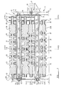
- a rolling mill embodying the invention comprises a plurality of roll passes for progressively forming a workpiece to a desired final cross-sectional shape.
- the number of passes is determined in accordance with conventional rolling mill practice. In the present example five roll passes are provided, although any suitable number of passes may be provided.
- Each pass is of the same construction as the final pass which is illustrated in Figures 2 - 4 except for the profile of the rolls which vary progressively through the mill in accordance with conventional rolling mill practice so as to progressively form an initially planar workpiece of strip of metal such as steel or aluminium to a desired final cross-sectional shape.
- Each roll pass comprises a pair of rotatable mountings 10, 11 disposed on opposite sides of a pass line P of the mill.
- Each rotatable mounting 10, 11 comprises a fabricated beam 12 of square cross-sectional shape which is supported at its opposite ends by stands 13 disposed on opposite sides of the mill and rotatably mounted thereon by bearings 14 in which stub axles 15 projecting from the beams 12 are rotatably received.
- the beams 12 are disposed vertically one above the other and the upper beam is provided with a hand wheel 16 by which the beam can be rotated.
- the upper beam 16 is provided with a sprocket 17 around which a chain 18 is entrained and the chain 18 is also entrained around a further sprocket 19 fixed to the adjacent end of the lower beam 12 so that rotation of the upper beam 12 by the hand wheel 16 is transmitted to the lower beam 12 so that the beams rotate through equal angular extents.
- Each beam 12 has a plurality of radially extending arms 20 on each of the four faces of the beam.
- the number and disposition of the radial arms 20 on each face is determined in accordance with the profile of a rolling means 21 a , - d , 22 a - d to be supported thereby.
- the beam 12 may have a different number of faces, (more or less than four) thus providing a different number of alternative profiles.
- Each rolling means 21 a - d is arranged to co-operate with a rolling means 22 a - d respectively to form the workpiece to the desired cross-sectional configuration at the rolling pass concerned.
- the radial arms 20 are provided with suitable bearing means 20′ whereby the rolling means 21 a - d , 22 a - d are rotatably carried thereby.
- Each rolling means 21 a - d of the upper mounting 10 is provided with a driving gear 23 and a driven gear 24 whilst each rolling means 22 a - d is provided with a driven gear 25 alone.
- the driving gear 23 and the driven gear 25 are brought into meshing engagement when an associated rolling means 21 a - d , 22 a - d respectively is brought into rolling position such as is occupied by the rolling means 21 c , 22 c shown in Figure 2.
- each rolling means 21 a - d is brought into meshing engagement with the driving gear 26 when the rolling means 21 a - d is brought into said rolling position.
- the driving gear 26 is driven by a drive shaft 27 which is itself driven via a universally jointed intermediate shaft 28 from a gear box 29.
- the gear box 29 is driven from a common drive or lay shaft 30 which extends longitudinally of the mill to drive the gear boxes 29, one at each roll pass, from a motor M.
- a peg 31, 32 is provided to be engaged in a slot 33 a - d , 34 a - d provided at one end of each face of each beam 12 so as to permit each beam 12 to be locked in a selected one of four different angular positions to hold a respective rolling means 21 a - d , 22 a - d in their rolling position.
- each rolling means 21 a - d , 22 a - d is machined from a solid cylinder to provide the desired configuration.
- each rolling means may be made from a plurality of components disposed longitudinally of the rolling means and clamped together by suitable means so as to rotate as a unit.
- a desired pair of rolling means 21 a - d , 22 a - d are brought into rolling position to form the workpiece to a desired final configuration.
- a clamping bolt 15 a of each beam is preferably then tightened to further secure the beams in position.
- the driving gear 26 may be arranged to mesh with a driven gear of the rolling means of the lower mounting 11 instead of a driven gear of the upper mounting 10 as described hereinbefore.
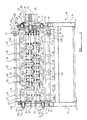
- Figure 5 illustrates another embodiment of the invention.
- the same reference numerals are used as are used in Figures 1 - 4 to refer to corresponding parts except that the upper mounting 10 and the upper rolling means 21 a - d in Figures 1 - 4 are referred to as 11 and 22 a - d respectively in Figure 5 whilst the lower mounting 11 and lower rolling means 22 a - d of Figures 1 - 4 are referred to as 10 and 21 a - d respectively in Figure 5.
- the embodiment shown in Figure 5 is essentially similar to that illustrated in Figures 1 - 4 except as described hereinafter and as will be seen by comparing Figure 5 with Figures 1 - 4.
- each rolling means 21 a - d , 22 a - d comprises a longitudinally extending shaft 50 which is supported for rotation in the bearings 20′ of the radial arms 20.
- Each shaft 50 carries a plurality of discrete roll elements 51 which may be single or multi-component members.
- the discrete roll elements 51 are secured to the shafts 21 c by grub screws or in any other conventional manner.
- elements 51 of appropriate shape are provided on all the shafts 21 a - d to suit the section being manufactured.
- the Figure 5 the rolling elements are not shown on the shafts 21 a - 22 a for convenience.
- the gear box 29 is mounted at a higher level than in the embodiment of Figures 1 - 4 and the driving gear 26 meshes with a driven gear 24 of a rolling means 21 a - d of the lower mounting 10 instead of a driven gear of the upper mounting as in Figures 1 - 4.
- Each rolling means 21 a - d of the lower mounting 10 is provided with a driving gear 23, as well as the driven gear 24 which is arranged to mesh with the driving gear 26.
- Each upper rolling means 22 a - d is provided with a driven gear 25 alone which is brought into meshing engagement with the driving gear 23 when the associated rolling means 21 a - d , 22 a - d respectively is brought into rolling position such as is occupied by the rolling means 21 c , 22 c shown in Figure 5.
- the lowermost parts of the section at each roll pass lies in a common horizontal plane so that as the sheet is progressively formed it is effectively progressively deformed upwardly from an original flat sheet lying in the horizontal plane. It is preferred to drive the lower of each pair of rolls at each roll pass as illustrated in Figure 5.
- components corresponding to the clamping bolts 15 a are provided but in this case have levers 52 fixed thereto for ease of tightening.
- the lower beam is provided with a lever, not shown, to permit manual rotation of the lower beam and hence of the upper beam through the socket 17, 19 and chain 18.
- the upper beam 12 has the bearings 14 carried in blocks 14 a which can be adjusted up and down in guideways 14 b under the control of screw threaded adjusters 14 c to vary the spacing of the rolling means 21 a - d , 22 a - d .
- a transmission means to transmit drive from the roll of the upper mounting 10, or lower mounting 11, to the rolls of the lower mounting 11, or upper mounting 10, respectively may be omitted.
- the workpiece is advanced through the mill solely by frictional engagement thereof by the respective upper or lower driven forming rolling means.
Landscapes
- Engineering & Computer Science (AREA)
- Mechanical Engineering (AREA)
- Metal Rolling (AREA)
Applications Claiming Priority (2)
| Application Number | Priority Date | Filing Date | Title |
|---|---|---|---|
| GB909011225A GB9011225D0 (en) | 1990-05-18 | 1990-05-18 | Rolling mill |
| GB9011225 | 1990-05-18 |
Publications (2)
| Publication Number | Publication Date |
|---|---|
| EP0457556A1 true EP0457556A1 (de) | 1991-11-21 |
| EP0457556B1 EP0457556B1 (de) | 1994-07-27 |
Family
ID=10676243
Family Applications (1)
| Application Number | Title | Priority Date | Filing Date |
|---|---|---|---|
| EP91304334A Expired - Lifetime EP0457556B1 (de) | 1990-05-18 | 1991-05-15 | Profilwalzmaschine |
Country Status (4)
| Country | Link |
|---|---|
| US (1) | US5109688A (de) |
| EP (1) | EP0457556B1 (de) |
| DE (1) | DE69103082T2 (de) |
| GB (2) | GB9011225D0 (de) |
Cited By (2)
| Publication number | Priority date | Publication date | Assignee | Title |
|---|---|---|---|---|
| EP0581985A1 (de) * | 1992-08-04 | 1994-02-09 | Urs Ritter | Profilwalzmaschine |
| WO1994009925A1 (en) * | 1992-10-25 | 1994-05-11 | Akv-Ortic Ab | Manufacturing line for shaping steel strips |
Families Citing this family (1)
| Publication number | Priority date | Publication date | Assignee | Title |
|---|---|---|---|---|
| SE529998C2 (sv) * | 2005-04-07 | 2008-02-05 | Sandvik Intellectual Property | En stödvalstrumma och en stödvalsenhet för en roterbar skäranordning |
Citations (3)
| Publication number | Priority date | Publication date | Assignee | Title |
|---|---|---|---|---|
| GB189411919A (en) * | 1894-06-20 | 1895-04-13 | William George Causer | Improvements in the Manufacture of Corrugated Metal Sheets,and in Means to be Employed in connection therewith. |
| DE2816993A1 (de) * | 1978-04-19 | 1979-10-31 | Fischer Kg J | Profilwalzmaschine |
| DE2556974B2 (de) * | 1975-12-18 | 1981-02-12 | J. Fischer Kg, 5902 Netphen | Profilwalzmaschine |
Family Cites Families (8)
| Publication number | Priority date | Publication date | Assignee | Title |
|---|---|---|---|---|
| US494904A (en) * | 1893-04-04 | Edwin henry story | ||
| US1936228A (en) * | 1931-01-22 | 1933-11-21 | Robertson Co H H | Apparatus for corrugating sheets |
| US3318130A (en) * | 1965-01-11 | 1967-05-09 | Sendzimir Inc T | Backed mill with readily exchangeable working rolls |
| US3453852A (en) * | 1967-06-01 | 1969-07-08 | Manco Mfg Co | Straightening apparatus for tubes,rods and the like |
| GB1552787A (en) * | 1976-06-29 | 1979-09-19 | Wilson A I | Rolling mill stand |
| US4724695A (en) * | 1986-12-08 | 1988-02-16 | Artos Engineering Company | Quickly convertible roller forming machine |
| SE8703922D0 (sv) * | 1987-10-09 | 1987-10-09 | Dobel Ab | Rullformningsmaskin |
| US4974435A (en) * | 1989-10-20 | 1990-12-04 | Jacky Vandenbroucke | Roll formed with quick automated tool changer |
-
1990
- 1990-05-18 GB GB909011225A patent/GB9011225D0/en active Pending
-
1991
- 1991-05-14 US US07/699,881 patent/US5109688A/en not_active Expired - Fee Related
- 1991-05-15 EP EP91304334A patent/EP0457556B1/de not_active Expired - Lifetime
- 1991-05-15 GB GB9110529A patent/GB2244441B/en not_active Expired - Fee Related
- 1991-05-15 DE DE69103082T patent/DE69103082T2/de not_active Expired - Fee Related
Patent Citations (3)
| Publication number | Priority date | Publication date | Assignee | Title |
|---|---|---|---|---|
| GB189411919A (en) * | 1894-06-20 | 1895-04-13 | William George Causer | Improvements in the Manufacture of Corrugated Metal Sheets,and in Means to be Employed in connection therewith. |
| DE2556974B2 (de) * | 1975-12-18 | 1981-02-12 | J. Fischer Kg, 5902 Netphen | Profilwalzmaschine |
| DE2816993A1 (de) * | 1978-04-19 | 1979-10-31 | Fischer Kg J | Profilwalzmaschine |
Cited By (2)
| Publication number | Priority date | Publication date | Assignee | Title |
|---|---|---|---|---|
| EP0581985A1 (de) * | 1992-08-04 | 1994-02-09 | Urs Ritter | Profilwalzmaschine |
| WO1994009925A1 (en) * | 1992-10-25 | 1994-05-11 | Akv-Ortic Ab | Manufacturing line for shaping steel strips |
Also Published As
| Publication number | Publication date |
|---|---|
| GB9110529D0 (en) | 1991-07-03 |
| DE69103082T2 (de) | 1994-12-08 |
| DE69103082D1 (de) | 1994-09-01 |
| EP0457556B1 (de) | 1994-07-27 |
| GB2244441A (en) | 1991-12-04 |
| GB2244441B (en) | 1994-03-16 |
| US5109688A (en) | 1992-05-05 |
| GB9011225D0 (en) | 1990-07-04 |
Similar Documents
| Publication | Publication Date | Title |
|---|---|---|
| US3945234A (en) | Tandem rolling mill arrangement | |
| CA2253087A1 (en) | Convertible roll forming apparatus | |
| EP0457556A1 (de) | Profilwalzmaschine | |
| US5259228A (en) | Rolling mill | |
| GB2086335A (en) | Walking beam | |
| EP3866992B1 (de) | Vorrichtung und verfahren zum flexiblen rollformen eines halbzeugs | |
| DE3119407A1 (de) | Anstellvorrichtung zum einstellen des walzenabstandes in walzgeruesten | |
| DE3341558A1 (de) | Taumelplanradgetriebe | |
| JPS597403A (ja) | 棒材その他の圧延機のための圧延ユニツト | |
| US3686919A (en) | Control and adjustment assembly for rolling mill cages | |
| EP2347148B2 (de) | Zahnrad und trommelantrieb | |
| CH618777A5 (en) | Planetary transmission, in particular for driving a plurality of closely spaced rolls | |
| EP3722019B1 (de) | Werkzeugeinbauhilfe | |
| US5293799A (en) | Punching and perforating unit with combined punching and perforating cylinders | |
| DE69309059T2 (de) | Getriebeaggregat zum antrieb von zwei im wesentlichen parallelen wellen | |
| EP0499156B1 (de) | Sperrdifferential für Antiblockiersystem | |
| DE102021129740A1 (de) | Rütteleinrichtung mit selbsteinstellenden Prallleisten | |
| DE1506505B2 (de) | Antreibbares kranlaufrad | |
| GB2279023A (en) | Rolling mill | |
| EP1256399B1 (de) | Querwalzmaschine | |
| DE102021211903B3 (de) | Umlaufrädergetriebe und neigbarer Solarpaneelträger mit einem Umlaufrädergetriebe | |
| DE4414098A1 (de) | Getriebe | |
| DE2158885A1 (de) | Walzgerüst zum Walzen von Metall, insbesondere Profilmaterial | |
| DE2511649A1 (de) | Antrieb der rollen der transportwalzen durch ein planetenradsystem fuer die rundmaschine zur herstellung eines kegelstumpfes aus einem kreisringsegmentfoermigen blech | |
| DE69410422T2 (de) | Drehantrieb für ein Zahnrad mit grossem Durchmesser |
Legal Events
| Date | Code | Title | Description |
|---|---|---|---|
| PUAI | Public reference made under article 153(3) epc to a published international application that has entered the european phase |
Free format text: ORIGINAL CODE: 0009012 |
|
| AK | Designated contracting states |
Kind code of ref document: A1 Designated state(s): BE DE DK ES FR GB IT NL SE |
|
| 17P | Request for examination filed |
Effective date: 19911014 |
|
| 17Q | First examination report despatched |
Effective date: 19930413 |
|
| GRAA | (expected) grant |
Free format text: ORIGINAL CODE: 0009210 |
|
| AK | Designated contracting states |
Kind code of ref document: B1 Designated state(s): BE DE DK ES FR IT NL SE |
|
| PG25 | Lapsed in a contracting state [announced via postgrant information from national office to epo] |
Ref country code: NL Effective date: 19940727 Ref country code: ES Free format text: THE PATENT HAS BEEN ANNULLED BY A DECISION OF A NATIONAL AUTHORITY Effective date: 19940727 Ref country code: DK Effective date: 19940727 Ref country code: BE Effective date: 19940727 |
|
| REF | Corresponds to: |
Ref document number: 69103082 Country of ref document: DE Date of ref document: 19940901 |
|
| ITF | It: translation for a ep patent filed | ||
| ET | Fr: translation filed | ||
| NLV1 | Nl: lapsed or annulled due to failure to fulfill the requirements of art. 29p and 29m of the patents act | ||
| EAL | Se: european patent in force in sweden |
Ref document number: 91304334.5 |
|
| PLBE | No opposition filed within time limit |
Free format text: ORIGINAL CODE: 0009261 |
|
| STAA | Information on the status of an ep patent application or granted ep patent |
Free format text: STATUS: NO OPPOSITION FILED WITHIN TIME LIMIT |
|
| 26N | No opposition filed | ||
| PGFP | Annual fee paid to national office [announced via postgrant information from national office to epo] |
Ref country code: SE Payment date: 20020508 Year of fee payment: 12 Ref country code: FR Payment date: 20020508 Year of fee payment: 12 |
|
| PGFP | Annual fee paid to national office [announced via postgrant information from national office to epo] |
Ref country code: DE Payment date: 20020522 Year of fee payment: 12 |
|
| PG25 | Lapsed in a contracting state [announced via postgrant information from national office to epo] |
Ref country code: SE Free format text: LAPSE BECAUSE OF NON-PAYMENT OF DUE FEES Effective date: 20030516 |
|
| PG25 | Lapsed in a contracting state [announced via postgrant information from national office to epo] |
Ref country code: DE Free format text: LAPSE BECAUSE OF NON-PAYMENT OF DUE FEES Effective date: 20031202 |
|
| EUG | Se: european patent has lapsed | ||
| PG25 | Lapsed in a contracting state [announced via postgrant information from national office to epo] |
Ref country code: FR Free format text: LAPSE BECAUSE OF NON-PAYMENT OF DUE FEES Effective date: 20040130 |
|
| REG | Reference to a national code |
Ref country code: FR Ref legal event code: ST |
|
| PG25 | Lapsed in a contracting state [announced via postgrant information from national office to epo] |
Ref country code: IT Free format text: LAPSE BECAUSE OF NON-PAYMENT OF DUE FEES;WARNING: LAPSES OF ITALIAN PATENTS WITH EFFECTIVE DATE BEFORE 2007 MAY HAVE OCCURRED AT ANY TIME BEFORE 2007. THE CORRECT EFFECTIVE DATE MAY BE DIFFERENT FROM THE ONE RECORDED. Effective date: 20050515 |