EP0457580A1 - Garment support rails - Google Patents
Garment support rails Download PDFInfo
- Publication number
- EP0457580A1 EP0457580A1 EP91304388A EP91304388A EP0457580A1 EP 0457580 A1 EP0457580 A1 EP 0457580A1 EP 91304388 A EP91304388 A EP 91304388A EP 91304388 A EP91304388 A EP 91304388A EP 0457580 A1 EP0457580 A1 EP 0457580A1
- Authority
- EP
- European Patent Office
- Prior art keywords
- garment
- rail
- web
- hook
- sets
- Prior art date
- Legal status (The legal status is an assumption and is not a legal conclusion. Google has not performed a legal analysis and makes no representation as to the accuracy of the status listed.)
- Granted
Links
- 239000000725 suspension Substances 0.000 claims description 3
- 238000005299 abrasion Methods 0.000 claims description 2
- 238000003780 insertion Methods 0.000 claims description 2
- 230000037431 insertion Effects 0.000 claims description 2
- 230000015572 biosynthetic process Effects 0.000 claims 1
- 238000006073 displacement reaction Methods 0.000 description 3
- 238000000034 method Methods 0.000 description 2
- 230000000694 effects Effects 0.000 description 1
- 239000003000 extruded plastic Substances 0.000 description 1
- 238000001125 extrusion Methods 0.000 description 1
- 239000000463 material Substances 0.000 description 1
- 238000005728 strengthening Methods 0.000 description 1
- 238000003466 welding Methods 0.000 description 1
Images
Classifications
-
- A—HUMAN NECESSITIES
- A47—FURNITURE; DOMESTIC ARTICLES OR APPLIANCES; COFFEE MILLS; SPICE MILLS; SUCTION CLEANERS IN GENERAL
- A47B—TABLES; DESKS; OFFICE FURNITURE; CABINETS; DRAWERS; GENERAL DETAILS OF FURNITURE
- A47B61/00—Wardrobes
- A47B61/06—Travelling or trunk wardrobes also made of cardboard or the like, e.g. provided with garment-holders, ironing board, washing outfit, for picnics
Definitions
- This invention relates to garment support rails intended for use as part of a system for the high volume transportation of garments on coat-hangers or "sets" in rigid sided box-vans, trucks, other vehicles or containers (hereinafter and in the claims, for convenience, simply referred to as “vehicles”).
- a number of rails span the width of the vehicle, and are attached at either end at or close to the inner side walls by suitable fitments or supporting structure. It is upon these rails that the garments are hung, usually by means of coat-hangers or "sets", the latter being a conveniently handled hooked fitment to which a number of garments on coat-hangers have been previously attached.
- the rails are commonly set at up to four separate height levels in vertical displacement for example, and up to perhaps fifty or so in longitudinal displacement for example, it is necessary that some or all of the rails be detachable or movable to facilitate loading or unloading.
- the known facility to detach or reposition the rails by sliding them into the roof space is also of substantial commercial importance, since once a garment consignment has been delivered this facility frees the vehicle to carry alternative loads on its return journey, or to be used generally for other purposes without disadvantage.
- this adaption is effected by supporting the garment rails below more substantial second decking beams by means of short pillars, struts or ties.
- the rail should form a fully stressed part of the rail/beam assembly when subjected to second decking loads.
- a normal pillar, strut or tie system cannot readily achieve this since it requires the end pillars, struts or ties to be of sufficient strength and to have sufficient integrity of attachment to the vehicle structure to impart fairly high tensile loads into the garment rails when the assembly is loaded. This is difficult without the pillars, struts or ties being of such a size that their presence reduces the number of hangers able to be carried.
- a garment support rail for use in a vehicle, the garment support rail being constituted by a beam with a depending configuration defining a suspension means from which garment hangers or "sets" can be suspended.
- the garment rail is of transverse open or closed box section to define the beam and with a depending integral web configured to define a hook structure from which garment hangers or "sets", can be suspended.
- the hook structure defines with the beam a slot extending the length of the garment rail for insertion or removal of the garment hangers, or "sets".
- Such a garment support rail has the necessary structural strength to permit it to function as a decking support beam, and the necessity to provide the aforesaid rail/beam assembly is avoided.
- the garment rail 10 is formed by an extrusion process for example, and is of a length adapted to span the internal width of the vehicle.
- the rail 10 is of open-bottomed box section, i.e. it is of inverted U-section which is defined by a top web 11 and two depending webs 12 and 13, whereof web 12 is longer, in vertical terms, than the web 13 and is inturned to define a hook configuration 14 from which garment hangers 15, or “sets", can be suspended.
- the hook configuration 14 and the lower end of the web 13 define a slot 16 to facilitate entry of the hooks 17 of the garment hangers 15, or “sets", which slot 16 is intermediate the top and bottom ends of the garment rail 10.
- the web 13 is disposed relative to the hook configuration 14 to act as a buffer or impediment to accidental or inadvertent de-railing of the garment hangers 15, or "sets".
- the upper edge of the slot 16, i.e. the lower inturned end 13A of the web 13, is offset relative to an imaginary vertical line drawn through the approximate centre of the hanger 15 or set hook in its normal rest position at 14C on the hook configuration 14. Should any hanger 15 be "bounced” upwards clear of the hook configuration 14 during transit, contact with the upper edge of the slot 16, i.e. end 13A, will tend to deflect it in a direction forwards and downwards back to its correct location, rather than allowing it to bounce off completely.
- This "buffer” feature eliminates de-railing and obviates the need (and expense) for a separate system to lock the hangers or "sets" in position during transit.
- the garment support rail or decking support beam 20 of Figure 2 is identical with that garment support rail of decking support beam 10 of Figure 1 save that the webs 21, 22 (equivalent to webs 12, 13) are interconnected by a web 23 below and parallel with the top web 24 and above the inturned "buffer" end 22A of the web 22.
- This web 23 has the effect of strengthening and stiffening the rail or beam and also provides a housing into which end fittings (not shown) can be located.
- the end fittings which form the intermediary attachment of the beam to the inner walls or vertical support track provided in the vehicle, may be fixed or may slide telescopically within the rectangle defined by webs 21 to 24.
- This telescopic operation at one or both ends of the rail or beam 20 enables the rail or beam effectively to change its length to accommodate variations between opposite inner wall spacing. It also allows the rail or beam to extend to accommodate angular displacements from the horizontal when pivotal end fitments are used and thereby enables either end of each rail or beam to be moved up or down the inner walls on vertical sliding tracks independently of each other to simply rail or beam.
- FIG. 3 shows a garment rail or decking support beam 30 which is of relatively thin-walled structure and which may be formed by a roll-forming or press-brake folding process for example.
- the rail/beam configuration is, in essence, of the same transverse cross-section as the rail/beam 20 of Figure 2.
- the web 31 (equivalent to web 23 of Figure 2) is a separate component of flattened inverted U-shape welded or otherwise secured between vertical webs 32, 33.
- This web 31 need not extend the full length of the rail/beam 30 but may be provided only at each end thereof to accommodate locating and positioning end fittings (not shown).
- the hook configuration 34 may be inturned as shown in Figures 1 and 2, but, in this instance it is formed with an outwardly-directed lip 35 having secured thereto by bonding, clipping or otherwise a wear or abrasion strip 36, say, of extruded plastics material for example.
- the end 33A of the web 33 which serves as the de-railment buffer is shown as an inturned configuration but it may alternatively be out-turned.
- An extruded strip, such as 36, may be fitted on this buffer end 33A, whether it be inturned or out-turned.
- Posts or ties 37 may optionally be fitted at intervals across the slot of the rail or beam 30 to enhance its load bearing capacity. These posts or ties may be welded or otherwise secured in position.
- an internal dividing wall or wall normal to the main longitudinal axis of the rail or beam may be fitted by welding or otherwise at the centre of the rail or beam and/or at spaced intervals along the length thereof.
- garment support rail/decking support beam has been shown and described as having a transverse closed or open box section it will be manifest that other sections may be employed, for example I-section, H-section or X-section.
Landscapes
- Holders For Apparel And Elements Relating To Apparel (AREA)
Abstract
Description
- This invention relates to garment support rails intended for use as part of a system for the high volume transportation of garments on coat-hangers or "sets" in rigid sided box-vans, trucks, other vehicles or containers (hereinafter and in the claims, for convenience, simply referred to as "vehicles").
- According to current practice, there are a number of systems commercially available for carrying garments, all of which have limitations known to those skilled in the art.
- In all known systems, a number of rails span the width of the vehicle, and are attached at either end at or close to the inner side walls by suitable fitments or supporting structure. It is upon these rails that the garments are hung, usually by means of coat-hangers or "sets", the latter being a conveniently handled hooked fitment to which a number of garments on coat-hangers have been previously attached.
- Since the vehicle is normally loaded from doors situated at one end, and the rails are commonly set at up to four separate height levels in vertical displacement for example, and up to perhaps fifty or so in longitudinal displacement for example, it is necessary that some or all of the rails be detachable or movable to facilitate loading or unloading. The known facility to detach or reposition the rails by sliding them into the roof space is also of substantial commercial importance, since once a garment consignment has been delivered this facility frees the vehicle to carry alternative loads on its return journey, or to be used generally for other purposes without disadvantage.
- In some situations, it would be highly advantageous to be able to adapt the vehicle to a "second deck" system - that is, to enable alternative loads to be carried both on the floor of the container and on a temporary deck (or decks) typically set at a metre or so above the floor or lower decks or decks to maximise the load carrying capacity.
- Currently, this adaption is effected by supporting the garment rails below more substantial second decking beams by means of short pillars, struts or ties. Ideally, to maximise the load bearing capacity and to reduce weight, cost and overall depth, the rail should form a fully stressed part of the rail/beam assembly when subjected to second decking loads. A normal pillar, strut or tie system cannot readily achieve this since it requires the end pillars, struts or ties to be of sufficient strength and to have sufficient integrity of attachment to the vehicle structure to impart fairly high tensile loads into the garment rails when the assembly is loaded. This is difficult without the pillars, struts or ties being of such a size that their presence reduces the number of hangers able to be carried.
- It is an object of the present invention to provide a garment support rail capable of functioning per se as a decking support.
- According to the present invention, therefore, there is provided a garment support rail for use in a vehicle, the garment support rail being constituted by a beam with a depending configuration defining a suspension means from which garment hangers or "sets" can be suspended.
- Preferably the garment rail is of transverse open or closed box section to define the beam and with a depending integral web configured to define a hook structure from which garment hangers or "sets", can be suspended.
- Preferably the hook structure defines with the beam a slot extending the length of the garment rail for insertion or removal of the garment hangers, or "sets".
- Such a garment support rail has the necessary structural strength to permit it to function as a decking support beam, and the necessity to provide the aforesaid rail/beam assembly is avoided.
- Embodiments of the present invention will now be described, by way of example, with reference to the accompanying drawings in which:-
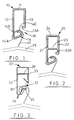
- Figure 1 is a transverse cross-section of a first embodiment of a garment rail/decking beam according to the present invention;
- Figure 2 is a transverse cross-section of a second embodiment of a garment rail/decking beam according to the invention; and
- Figure 3 is a transverse cross-section of a third embodiment of a garment rail/decking beam according to the invention.
- Referring to Figure 1, the
garment rail 10 is formed by an extrusion process for example, and is of a length adapted to span the internal width of the vehicle. - The
rail 10 is of open-bottomed box section, i.e. it is of inverted U-section which is defined by atop web 11 and two dependingwebs web 12 is longer, in vertical terms, than theweb 13 and is inturned to define ahook configuration 14 from whichgarment hangers 15, or "sets", can be suspended. - The
hook configuration 14 and the lower end of theweb 13 define aslot 16 to facilitate entry of thehooks 17 of thegarment hangers 15, or "sets", whichslot 16 is intermediate the top and bottom ends of thegarment rail 10. - The garment
suspension hook configuration 14, i.e. from the lower end 14A of theweb 12 to theinner tip 14B of thehook configuration 14, of the garment rail ordecking support beam 10, when the latter is loaded across its span either in its primary function as a garment support rail or its secondary function as a decking support beam, due to its integrity with the box-section of the rail or beam, constitutes a stressed part of the rail/beam structure. This is achieved by the provision of the continuous (unbroken)vertical shear web 12, especially across the central third of the span. - The
web 13 is disposed relative to thehook configuration 14 to act as a buffer or impediment to accidental or inadvertent de-railing of thegarment hangers 15, or "sets". - More precisely the upper edge of the
slot 16, i.e. the lower inturnedend 13A of theweb 13, is offset relative to an imaginary vertical line drawn through the approximate centre of thehanger 15 or set hook in its normal rest position at 14C on thehook configuration 14. Should anyhanger 15 be "bounced" upwards clear of thehook configuration 14 during transit, contact with the upper edge of theslot 16, i.e.end 13A, will tend to deflect it in a direction forwards and downwards back to its correct location, rather than allowing it to bounce off completely. This "buffer" feature eliminates de-railing and obviates the need (and expense) for a separate system to lock the hangers or "sets" in position during transit. - The garment support rail or
decking support beam 20 of Figure 2 is identical with that garment support rail ofdecking support beam 10 of Figure 1 save that the webs 21, 22 (equivalent towebs 12, 13) are interconnected by aweb 23 below and parallel with thetop web 24 and above the inturned "buffer"end 22A of theweb 22. - This
web 23 has the effect of strengthening and stiffening the rail or beam and also provides a housing into which end fittings (not shown) can be located. The end fittings, which form the intermediary attachment of the beam to the inner walls or vertical support track provided in the vehicle, may be fixed or may slide telescopically within the rectangle defined by webs 21 to 24. - This telescopic operation at one or both ends of the rail or
beam 20 enables the rail or beam effectively to change its length to accommodate variations between opposite inner wall spacing. It also allows the rail or beam to extend to accommodate angular displacements from the horizontal when pivotal end fitments are used and thereby enables either end of each rail or beam to be moved up or down the inner walls on vertical sliding tracks independently of each other to simply rail or beam. - Reference is now made to Figure 3 which shows a garment rail or
decking support beam 30 which is of relatively thin-walled structure and which may be formed by a roll-forming or press-brake folding process for example. - In this embodiment, the rail/beam configuration is, in essence, of the same transverse cross-section as the rail/
beam 20 of Figure 2. - However, the web 31 (equivalent to
web 23 of Figure 2) is a separate component of flattened inverted U-shape welded or otherwise secured betweenvertical webs - This
web 31 need not extend the full length of the rail/beam 30 but may be provided only at each end thereof to accommodate locating and positioning end fittings (not shown). - The
hook configuration 34 may be inturned as shown in Figures 1 and 2, but, in this instance it is formed with an outwardly-directedlip 35 having secured thereto by bonding, clipping or otherwise a wear orabrasion strip 36, say, of extruded plastics material for example. - The end 33A of the
web 33 which serves as the de-railment buffer is shown as an inturned configuration but it may alternatively be out-turned. - An extruded strip, such as 36, may be fitted on this buffer end 33A, whether it be inturned or out-turned.
- Posts or
ties 37 may optionally be fitted at intervals across the slot of the rail orbeam 30 to enhance its load bearing capacity. These posts or ties may be welded or otherwise secured in position. - Alternatively, or additionally, an internal dividing wall or wall normal to the main longitudinal axis of the rail or beam may be fitted by welding or otherwise at the centre of the rail or beam and/or at spaced intervals along the length thereof.
- While the garment support rail/decking support beam has been shown and described as having a transverse closed or open box section it will be manifest that other sections may be employed, for example I-section, H-section or X-section.
Claims (10)
- A garment support rail for use in a vehicle, the garment support rail being constituted by a beam with a depending configuration defining suspension means from which garment hangers, or "sets" can be suspended.
- A garment rail as claimed in claim 1 having a beam structure defined by a transverse open or closed box cross-section with a depending integral web configured to define a hook structure from which the garment hangers, or "sets" can be hung.
- A garment rail as claimed in claim 2 in which the hook structure defines with the beam a slot extending the length of the garment rail for insertion or removal of the garment hangers or "sets".
- A garment rail as claimed in claim 3 comprising a top horizontal web bridging and interconnecting two spaced parallel vertical webs, whereof one is vertically longer than the other end and is inturned to define the hook structure below the bottom end of the other web and located transversely intermediate both webs.
- A garment rail as claimed in claim 4 in which the lower end of the other web which is spaced inwardly and transversely from the hook configuration serves as a buffer to resist inadvertent garment hanger, or set, de-railment from the hook configuration.
- A garment rail as claimed in claim 5, in which the lower end of the other web is inturned.
- A garment rail as claimed in any one of claims 4 to 6 in which a transverse web below and parallel with top web defines, at the ends of the garment rail at least, sockets for receiving end fittings for securing the garment rail between walls of a vehicle.
- A garment rail as claimed in any one of claims 2 to 7 in which the hook formation is provided with a wear or abrasion resistant strip.
- A garment rail as claimed in any one of claims 5 to 8 comprising, at spaced intervals along the rail, ties connecting the lower end of the other web and the hook structure and/or an internal vertical wall or walls connecting the vertical webs to provide increased structural length.
- A beam for supporting load-carrying decking in a vehicle and being formed or provided with a slot along its length to define a rail from which garment hangers, or "sets" can be suspended.
Applications Claiming Priority (2)
| Application Number | Priority Date | Filing Date | Title |
|---|---|---|---|
| GB909011069A GB9011069D0 (en) | 1990-05-17 | 1990-05-17 | Combined garment-rail/decking-beam |
| GB9011069 | 1990-05-17 |
Publications (2)
| Publication Number | Publication Date |
|---|---|
| EP0457580A1 true EP0457580A1 (en) | 1991-11-21 |
| EP0457580B1 EP0457580B1 (en) | 1996-07-17 |
Family
ID=10676145
Family Applications (1)
| Application Number | Title | Priority Date | Filing Date |
|---|---|---|---|
| EP19910304388 Expired - Lifetime EP0457580B1 (en) | 1990-05-17 | 1991-05-16 | Garment support rails |
Country Status (3)
| Country | Link |
|---|---|
| EP (1) | EP0457580B1 (en) |
| DE (1) | DE69120868T2 (en) |
| GB (1) | GB9011069D0 (en) |
Cited By (2)
| Publication number | Priority date | Publication date | Assignee | Title |
|---|---|---|---|---|
| DE102010025899A1 (en) * | 2010-07-02 | 2012-01-05 | TS Gesellschaft für Transport- und Sicherungssysteme mbH | Goods transporting device i.e. circular rod, for transporting e.g. fur coats, in hanger of transport vehicle, has bottom region arranged in stiffener region, where rod is partially protruded from path of regions to external periphery |
| US10690111B2 (en) | 2016-12-02 | 2020-06-23 | General Electric Company | Wind turbine rotor blade |
Citations (4)
| Publication number | Priority date | Publication date | Assignee | Title |
|---|---|---|---|---|
| US2904190A (en) * | 1954-12-29 | 1959-09-15 | Lanzit Corrugated Box Company | Hanger bar |
| GB2033741A (en) * | 1978-08-22 | 1980-05-29 | Aeroquip Ltd | Garment hanger rail assembly |
| GB2044094A (en) * | 1979-03-12 | 1980-10-15 | Roger D P H | Improvements in garment rails |
| CA1191115A (en) * | 1983-01-18 | 1985-07-30 | Dioniso Difranco | Support bar |
-
1990
- 1990-05-17 GB GB909011069A patent/GB9011069D0/en active Pending
-
1991
- 1991-05-16 DE DE1991620868 patent/DE69120868T2/en not_active Expired - Fee Related
- 1991-05-16 EP EP19910304388 patent/EP0457580B1/en not_active Expired - Lifetime
Patent Citations (4)
| Publication number | Priority date | Publication date | Assignee | Title |
|---|---|---|---|---|
| US2904190A (en) * | 1954-12-29 | 1959-09-15 | Lanzit Corrugated Box Company | Hanger bar |
| GB2033741A (en) * | 1978-08-22 | 1980-05-29 | Aeroquip Ltd | Garment hanger rail assembly |
| GB2044094A (en) * | 1979-03-12 | 1980-10-15 | Roger D P H | Improvements in garment rails |
| CA1191115A (en) * | 1983-01-18 | 1985-07-30 | Dioniso Difranco | Support bar |
Cited By (3)
| Publication number | Priority date | Publication date | Assignee | Title |
|---|---|---|---|---|
| DE102010025899A1 (en) * | 2010-07-02 | 2012-01-05 | TS Gesellschaft für Transport- und Sicherungssysteme mbH | Goods transporting device i.e. circular rod, for transporting e.g. fur coats, in hanger of transport vehicle, has bottom region arranged in stiffener region, where rod is partially protruded from path of regions to external periphery |
| DE102010025899B4 (en) | 2010-07-02 | 2018-07-05 | TS Gesellschaft für Transport- und Sicherungssysteme mbH | Device for carrying ironing garments |
| US10690111B2 (en) | 2016-12-02 | 2020-06-23 | General Electric Company | Wind turbine rotor blade |
Also Published As
| Publication number | Publication date |
|---|---|
| DE69120868T2 (en) | 1996-12-19 |
| DE69120868D1 (en) | 1996-08-22 |
| GB9011069D0 (en) | 1990-07-04 |
| EP0457580B1 (en) | 1996-07-17 |
Similar Documents
| Publication | Publication Date | Title |
|---|---|---|
| US5375534A (en) | Intermediate deck structure for vehicles | |
| US4771706A (en) | Container carrying railroad car with support castings | |
| US5520489A (en) | Retractable guide assembly for changing the effective width of a railroad freight car container well | |
| US5037255A (en) | Wheel chock for a motor vehicle container | |
| US4889055A (en) | Railroad car for container transport | |
| US6068214A (en) | System for securing a support to an aircraft floor | |
| US4876968A (en) | Container carrying railroad car with improved support system | |
| US4718353A (en) | Container carrying railroad car with walkways for access to containers | |
| US4750633A (en) | Storage and transportation case for shelf system | |
| US5720228A (en) | Folding flatrack | |
| AU631642B2 (en) | Dual purpose depressed center railway flat car | |
| US3815517A (en) | Automobile container | |
| US6003445A (en) | Retractable container stop and guide assembly for railroad freight cars | |
| US5749686A (en) | Pivotable sidewall mounted container stop for railcar well | |
| EP0457580B1 (en) | Garment support rails | |
| PL199044B1 (en) | Tarpaulin fixture | |
| US20020073886A1 (en) | Top chord structure | |
| CN1115265C (en) | Lateral tarpaulin suspension structure | |
| US5832839A (en) | Curved flange sidewall construction for railcar end structure | |
| PL199972B1 (en) | Freight car for transporting coiled materials | |
| EP0764126B1 (en) | A container | |
| US2319471A (en) | Railway car structure | |
| US12415455B2 (en) | Vertical cargo support system for a cargo space | |
| EP0805098A1 (en) | Ringed stanchion and removable support for a mezzanine platform of a lorry | |
| CA2391107C (en) | Railroad well car |
Legal Events
| Date | Code | Title | Description |
|---|---|---|---|
| PUAI | Public reference made under article 153(3) epc to a published international application that has entered the european phase |
Free format text: ORIGINAL CODE: 0009012 |
|
| AK | Designated contracting states |
Kind code of ref document: A1 Designated state(s): DE ES FR GB IT NL SE |
|
| 17P | Request for examination filed |
Effective date: 19920401 |
|
| 17Q | First examination report despatched |
Effective date: 19930702 |
|
| RAP1 | Party data changed (applicant data changed or rights of an application transferred) |
Owner name: SHORFAST LIMITED |
|
| 18D | Application deemed to be withdrawn |
Effective date: 19941115 |
|
| 18RA | Request filed for re-establishment of rights before grant |
Effective date: 19950526 |
|
| GRAH | Despatch of communication of intention to grant a patent |
Free format text: ORIGINAL CODE: EPIDOS IGRA |
|
| D18D | Application deemed to be withdrawn (deleted) | ||
| GRAA | (expected) grant |
Free format text: ORIGINAL CODE: 0009210 |
|
| AK | Designated contracting states |
Kind code of ref document: B1 Designated state(s): DE ES FR GB IT NL SE |
|
| PG25 | Lapsed in a contracting state [announced via postgrant information from national office to epo] |
Ref country code: IT Free format text: LAPSE BECAUSE OF FAILURE TO SUBMIT A TRANSLATION OF THE DESCRIPTION OR TO PAY THE FEE WITHIN THE PRESCRIBED TIME-LIMIT;WARNING: LAPSES OF ITALIAN PATENTS WITH EFFECTIVE DATE BEFORE 2007 MAY HAVE OCCURRED AT ANY TIME BEFORE 2007. THE CORRECT EFFECTIVE DATE MAY BE DIFFERENT FROM THE ONE RECORDED. Effective date: 19960717 Ref country code: ES Free format text: THE PATENT HAS BEEN ANNULLED BY A DECISION OF A NATIONAL AUTHORITY Effective date: 19960717 |
|
| REF | Corresponds to: |
Ref document number: 69120868 Country of ref document: DE Date of ref document: 19960822 |
|
| ET | Fr: translation filed | ||
| PG25 | Lapsed in a contracting state [announced via postgrant information from national office to epo] |
Ref country code: SE Effective date: 19961017 |
|
| PGFP | Annual fee paid to national office [announced via postgrant information from national office to epo] |
Ref country code: FR Payment date: 19970513 Year of fee payment: 7 |
|
| PGFP | Annual fee paid to national office [announced via postgrant information from national office to epo] |
Ref country code: DE Payment date: 19970523 Year of fee payment: 7 |
|
| PLBE | No opposition filed within time limit |
Free format text: ORIGINAL CODE: 0009261 |
|
| STAA | Information on the status of an ep patent application or granted ep patent |
Free format text: STATUS: NO OPPOSITION FILED WITHIN TIME LIMIT |
|
| PGFP | Annual fee paid to national office [announced via postgrant information from national office to epo] |
Ref country code: NL Payment date: 19970529 Year of fee payment: 7 |
|
| 26N | No opposition filed | ||
| PG25 | Lapsed in a contracting state [announced via postgrant information from national office to epo] |
Ref country code: FR Free format text: LAPSE BECAUSE OF NON-PAYMENT OF DUE FEES Effective date: 19980531 |
|
| PG25 | Lapsed in a contracting state [announced via postgrant information from national office to epo] |
Ref country code: NL Free format text: LAPSE BECAUSE OF NON-PAYMENT OF DUE FEES Effective date: 19981201 |
|
| NLV4 | Nl: lapsed or anulled due to non-payment of the annual fee |
Effective date: 19981201 |
|
| PG25 | Lapsed in a contracting state [announced via postgrant information from national office to epo] |
Ref country code: DE Free format text: LAPSE BECAUSE OF NON-PAYMENT OF DUE FEES Effective date: 19990302 |
|
| REG | Reference to a national code |
Ref country code: FR Ref legal event code: ST |
|
| REG | Reference to a national code |
Ref country code: GB Ref legal event code: IF02 |
|
| PGFP | Annual fee paid to national office [announced via postgrant information from national office to epo] |
Ref country code: GB Payment date: 20060510 Year of fee payment: 16 |
|
| GBPC | Gb: european patent ceased through non-payment of renewal fee |
Effective date: 20070516 |
|
| PG25 | Lapsed in a contracting state [announced via postgrant information from national office to epo] |
Ref country code: GB Free format text: LAPSE BECAUSE OF NON-PAYMENT OF DUE FEES Effective date: 20070516 |