EP0457612A2 - Profilage dans le domaine d'objectif de surfaces optiques utilisant l'ablation par lumière d'excimer laser - Google Patents
Profilage dans le domaine d'objectif de surfaces optiques utilisant l'ablation par lumière d'excimer laser Download PDFInfo
- Publication number
- EP0457612A2 EP0457612A2 EP91304467A EP91304467A EP0457612A2 EP 0457612 A2 EP0457612 A2 EP 0457612A2 EP 91304467 A EP91304467 A EP 91304467A EP 91304467 A EP91304467 A EP 91304467A EP 0457612 A2 EP0457612 A2 EP 0457612A2
- Authority
- EP
- European Patent Office
- Prior art keywords
- target
- axis
- lens
- along
- ablation
- Prior art date
- Legal status (The legal status is an assumption and is not a legal conclusion. Google has not performed a legal analysis and makes no representation as to the accuracy of the status listed.)
- Granted
Links
Images


Classifications
-
- B—PERFORMING OPERATIONS; TRANSPORTING
- B29—WORKING OF PLASTICS; WORKING OF SUBSTANCES IN A PLASTIC STATE IN GENERAL
- B29D—PRODUCING PARTICULAR ARTICLES FROM PLASTICS OR FROM SUBSTANCES IN A PLASTIC STATE
- B29D11/00—Producing optical elements, e.g. lenses or prisms
- B29D11/00009—Production of simple or compound lenses
- B29D11/00432—Auxiliary operations, e.g. machines for filling the moulds
- B29D11/00461—Adjusting the refractive index, e.g. after implanting
-
- B—PERFORMING OPERATIONS; TRANSPORTING
- B23—MACHINE TOOLS; METAL-WORKING NOT OTHERWISE PROVIDED FOR
- B23K—SOLDERING OR UNSOLDERING; WELDING; CLADDING OR PLATING BY SOLDERING OR WELDING; CUTTING BY APPLYING HEAT LOCALLY, e.g. FLAME CUTTING; WORKING BY LASER BEAM
- B23K2103/00—Materials to be soldered, welded or cut
- B23K2103/30—Organic materials
- B23K2103/42—Plastics other than composite materials
-
- B—PERFORMING OPERATIONS; TRANSPORTING
- B23—MACHINE TOOLS; METAL-WORKING NOT OTHERWISE PROVIDED FOR
- B23K—SOLDERING OR UNSOLDERING; WELDING; CLADDING OR PLATING BY SOLDERING OR WELDING; CUTTING BY APPLYING HEAT LOCALLY, e.g. FLAME CUTTING; WORKING BY LASER BEAM
- B23K2103/00—Materials to be soldered, welded or cut
- B23K2103/50—Inorganic materials other than metals or composite materials
Definitions
- the present invention allows the use of an excimer laser to selectively alter the surface of an optical article and provides a highly effective and precise means for doing so.
- the present invention involves a method for reconfiguring the surface of an optical article.
- the present invention is particularly useful in producing toric surfaced optical articles with much more accuracy and precision than have been heretofore available.
- Figure 1A is the graphical representation of the shape of the cross-section of an excimer laser beam and shows of the energy distribution of the excimer laser in its x and y coordinates respectively.
- Figure 2 is an illustration of an apparatus used to practice the present invention where the laser beam is scanned across the surface of the target contact lens blank.
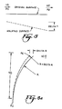
- Figure 3 is a schematic representation of an optical target which defines certain dimensions critical to the relationship of the scanning modality to ablation profile.
- Figure 3a is a schematic representation of an optical target defining dimensions and parameters used in defining the effect of ablation on radius of curvature of the target surface.
- Figure 4 shows the surface of a contact lens with a lathed surface.
- Figures 5 and 6 show the interferogram of a toric contact lens made by the claimed process.
- Figure 7 shows an interferogram of a commercially available toric contact lens.
- Figure 8 shows the interferogram of a lens whose spherical power has been changed by the present invention.
- the present invention relates to a new method of modifying optical surfaces to produce changes in their spherical or cylindrical refractive power.
- This new method employs high energy radiation to ablate material from a contact lens blank in a controlled fashion in order to produce a desired contact lens configuration.
- the method takes advantage of the relatively fixed pulse beam intensity of an excimer laser beam to sweep across the domain of an optical surface. By controlling the rate at which a beam is swept across the target along a given axis, the degree of ablation along that axis at any given point can be controlled.
- a beam from an excimer laser is roughly rectangular in cross-section and has a roughly uniform radiation intensity across one axis of symmetry.
- the beam intensity is also not absolutely uniform, however, its profile can be measured and accounted for in the process.
- the main aspect of the beam which is substantially fixed is the pulse intensity profile. This characteristic allows, according to invention claimed and described, to control the photoablation of an optical surface.
- Figure 1 shows a typical cross-section of an excimer laser along with the intensity distributions of the laser along its x and y coordinates.
- the intensity across the x axis of the beam is substantially uniform everywhere except at the edges.
- the invention describes a method for truncating the beam edges and thus provides a beam to the target of uniform intensity.
- Controlled ablation of the complete lens surface is accomplished by scanning the beam along its y axis across the optical surface being altered. When this scanning is done at a fixed velocity, the effect is simply to broaden the y axis of the beam profile as experienced by the target optical surface.
- excimer lasers operate in short pulses of about 20 nanoseconds and has a total pulse energy very consistent from pulse to pulse.
- the ablation process contemplated here requires a multitude of pulses in order to accomplish the desired objective.
- the excimer laser beam domain can be scanned across the target optical surface in a fashion to effect a linear or nonlinear, smooth and continuous ablation profile along one of the target's axes.
- Scanning the excimer laser beam can be accomplished by at least two means.
- Figure 2 shows an approach where the beam (1) is reflected 90° by a 45 degree fixed reflecting mirror (2). The beam is then reflected 90 degrees by a scannable mirror (3), which may be a total reflectance mirror or which can be a partial transmittance mirror.
- a scannable mirror (3) which may be a total reflectance mirror or which can be a partial transmittance mirror.
- mirror means for monitoring the beam profile of the excimer laser can be provided.
- Means for moving the scanning mirror (4) parallel to the initial beam path are provided which allows the mirror to shift the beam from its incident path and scan the beam domain across the target optical surface.
- Another method of practicing the invention involves the use of a mirror whose angle of incidence to the beam can be varied in order to sweep the beam domain across the target optical surface.
- the mirror In place of the fixed angle mirror(3) in the apparatus shown in figure 2 the mirror would be allowed to pivot in the plane of the axis being swept by the laser through the target. No other means, such as the linear servo-mechanism(4) found in the diagram would be necessary to effect the beam scanning, although a combination of linearly scanning the mirror in conjunction with pivoting the lens could be used.
- the degree of photoablation will be related to the velocity of the mirror (2) as it moves along axis of z, and the ablation would be uniform across the target optical surface in the event the mirror velocity was constant.
- photoablation as a function of y is related to the instantaneous velocity of the beam along the y axis (or the velocity of the mirror along the z axis) one can control the degree of photoablation by controlling the velocity profile of the mirror as it sweeps the beam across the target domain.
- Figure 2 also shows the apparatus as having a lens (5) which reduces the beam and thus increases the intensity of the beam as it is incident on the target (6). It should be understood that this element is optional in the practice of the invention, the beam could be used in the present invention without reducing its cross-sectional dimensions.
- T R1N/V where K1 is a constant.
- K and K1 are constants for the ablation of a given material in a specific environment. Thus, these constants are dependent upon target material composition, atmospheric conditions ambient to the target, wavelength of the beam, and beam intensity.
- delta T K . H . N(V2 - V1)/(V1 . V2) where V1 and V2 are the velocities of the beam on the target at points P1 and P2, and delta T is the difference in material removal between the two points(see Figure 3).
- the ablation profile is, of course, controlled by the product of the beam intensity profile function, which includes a pulse rate function, with the scanning velocity profile function.
- the beam pule rate is constant velocity will be related to ablation as V + A/Y o 2 where V is the instantaneous velocity of the beam as it is scanned, A is an ablation constant, and Y o is the distance of the beam from the axis of symmetry of the induced cylinder in the target, where such ablation causes a cylindrical component to be induced into the target surface.
- the desired ablation profile required to induce a change in cylinder power can also be accomplished by controlling the pulse rate of the laser. Accomplishing a given profile of ablation is dependent upon controlling the product of scan speed as a function of time (V) and the pulse rate of the laser as a function of time.
- the ablation profile can be controlled with constant sweep velocity by controlling the pulse rate of the laser.
- the repetition rate H could be varied instead of or as well as the scan velocity for different points on the surface.
- the amount of material removed at each point is proportional to the repetition rate as shown in Equation 1. If the velocity is kept uniform, then the variation in repetition rate required to produce any given profile can be readily derived in exactly the same way as for the velocity profile using Equation 1 at each point.
- Equation 1 If the velocity is varied as well as the repetition rate then the ratio of H to V must be used to ensure the etch depth at each point agrees with Equation 1. If multiple profile types are to be added together, then either the repetition rate H or the velocity V must be made the same for each profile distribution for each point. This is a trivial transformation using Equation 1. It should also be obvious that the additive process can still be used where both the repetition rate and velocity change at all points in the distribution because each point can be treated separately. The functions generated for repetition rate and velocity should, however, be continuous over the area to be etched.
- the means used to control the movement of the scanning mirror can be provided by a servo-mechanism driven by a stepper motor controlled through digital electronic means.
- the velocity profile can be controlled via a computer program and can be of any desired form.
- Another way of practicing this invention requires the target optical surface to be moved in a controlled fashion along axis x through the laser beam domain to effect the controlled ablation. This varies from the approach shown in Figure 2 in that it allows one to move the target rather than the beam.
- the fixed target configuration is determined by the initial target configuration and the degree of ablation as a function of x and y across the surface of the target.
- a lens from a contact lens button (essentially a disk of contact lens material).
- the contact lens blank can be substantially in the form of a spherical contact lens.
- the present method is better able to produce toric lenses with relatively low degrees of toricity (in particular, this is where the radius of curvature along the x axis, R curvature x , is close to the radius of curvature along the y axis, R curvature y .
- Another advantage of the system is that it is able to produce very accurate high cylinder toric lenses as well. In other words, the two radii being produced in the toric lens can be specified to a degree of precision far greater than is available through state of the art lathing techniques.
- the present method can be used to form both front surface toric lenses and back surface lenses, as one skilled in the art should appreciate.
- the method can also be used to produce high quality spherical lenses and lenses with bifocal optics and other configurations.
- bifocal lenses could be produced by masking a domain of the target and inducing spherical power change over the unmasked domain, thus producing a lens with two domains of different powers.
- the present method can be used on any plastic contact lens material as long as the radiation source used has sufficient energy and the proper wavelength to induce photo- ablation.
- Specific materials include the nonhydrated forms of poly 2-hydroxyethylmethacrylate (pHEMA), poly N-vinyl-2-pyrrolidone (pNVP), polymethylmethacrylate(pMMA), and copolymers of the above as well as other contact lens materials known to those skilled in the art.
- Gas permeable materials may be used as well as silicone based contact lens materials, especially fluorosilicone based materials.
- the following examples illustrate some of the applications of the present invention.
- the examples do not exhaust all of the possibilities of the present invention to shape optical target surfaces.
- No examples are given of corneal shaping although the same procedures used to shape contact lenses could generally be used to shape the optical surface of the eye. In such cases, the cornea would be considered to be a target optical surface.
- An unhydrated soft contact lens blank with a spherical posterior surface was aligned in the apparatus shown in Figure 2 as the optical target surface.
- This lens was made from Polymacon r material, a material widely used to make soft contact lenses.
- the posterior surface of the lens was scanned by the excimer beam as the scanner was scanned along the z axis in a nonlinear fashion that took more material from the edges of the lens than from the center along one axis.
- the lens was shown prior to being scanned by the excimer laser to be very close to a perfect sphere by interferometeric means.
- the interferogram of the lens prior to laser ablation is shown in Figure 4.
- the Figure shows that the whole posterior surface of the lens is within a few interference fringes of being spherical which translates to a deviation across the face of the lens of less than 1 micron.
- the lens is toric.
- Figures 5 and 6 show interferograms along the two axis of the posterior lens surface. As is clearly shown along each of the axis, the lens is within several interference fringes of having a given radii along that axis and some other radii along the other axis. This indicates that the two radii of the toric lens were precisely what had been anticipated.
- the radii of the two axii were intended to be 6.996 and 7.115 mm and the actual observed radii were 6.991 and 7.108 mm.
- the interferometer of a commercially available toric lens is shown in Figure 7. Here at least 20 interference fringes can be seen across the posterior surface of the lens.
- a lens blank with a spherical posterior surface was mounted in the apparatus shown in Figure 2.
- the lens was then scanned along an axis according to a function which would change the cylinder power of the lens along that axis.
- the lens was rotated 90 degrees and the lens was scanned again using the same scan function as employed on the first scanning sweep.
- the lens was then selected to interferometeric analysis which showed that the spherical power of the lens was changed and that the lens still possessed an almost perfect posterior surface, albeit with a different power than the original blank.
- the interferogram of the ablated lens is shown in Figure 8. As can be seen, there are few interference fringes across the whole posterior optical surface of the lens.
- a lens blank with a spherical posterior surface was mounted in the apparatus shown in Figure 2.
- the lens was scanned twice along one axis to induce a cylinder then turned through a 90 degree angle and scanned once with the same parameters. These cylindrical components add to produce a sphere change in power and a resultant cylinder change in power.
- the initial radius of the surface was 7.470mm. After both sets of scans, the surface had two radii in perpendicular meridians of 7.382 and 7.292, indicating a 0.088mm change in spherical radius with an additional 0.090mm cylinder.
Landscapes
- Engineering & Computer Science (AREA)
- Health & Medical Sciences (AREA)
- Manufacturing & Machinery (AREA)
- Ophthalmology & Optometry (AREA)
- Mechanical Engineering (AREA)
- Laser Beam Processing (AREA)
- Eyeglasses (AREA)
- Glass Compositions (AREA)
- Treatments Of Macromolecular Shaped Articles (AREA)
- Lasers (AREA)
- Addition Polymer Or Copolymer, Post-Treatments, Or Chemical Modifications (AREA)
- Grinding And Polishing Of Tertiary Curved Surfaces And Surfaces With Complex Shapes (AREA)
Applications Claiming Priority (4)
| Application Number | Priority Date | Filing Date | Title |
|---|---|---|---|
| US525515 | 1990-05-18 | ||
| US07/525,515 US5061342A (en) | 1990-05-18 | 1990-05-18 | Target domain profiling of target optical surfaces using excimer laser photoablation |
| AU86851/91A AU646696B2 (en) | 1990-05-18 | 1991-10-29 | Target domain profiling of target optical surfaces using excimer laser photoablation |
| AU57596/94A AU654639B2 (en) | 1990-05-18 | 1994-03-04 | Target domain profiling of target optical surfaces using excimer laser photoablation |
Publications (3)
| Publication Number | Publication Date |
|---|---|
| EP0457612A2 true EP0457612A2 (fr) | 1991-11-21 |
| EP0457612A3 EP0457612A3 (en) | 1992-03-18 |
| EP0457612B1 EP0457612B1 (fr) | 1996-01-10 |
Family
ID=27155153
Family Applications (1)
| Application Number | Title | Priority Date | Filing Date |
|---|---|---|---|
| EP91304467A Expired - Lifetime EP0457612B1 (fr) | 1990-05-18 | 1991-05-17 | Profilage dans le domaine d'objectif de surfaces optiques utilisant l'ablation par lumière d'excimer laser |
Country Status (7)
| Country | Link |
|---|---|
| US (2) | US5061342A (fr) |
| EP (1) | EP0457612B1 (fr) |
| JP (1) | JP3308281B2 (fr) |
| CN (1) | CN1029597C (fr) |
| AT (1) | ATE132785T1 (fr) |
| AU (2) | AU646696B2 (fr) |
| DE (1) | DE69116219T2 (fr) |
Cited By (14)
| Publication number | Priority date | Publication date | Assignee | Title |
|---|---|---|---|---|
| WO1994007638A1 (fr) * | 1992-09-29 | 1994-04-14 | Bausch & Lomb Incorporated | Procede pour nettoyer les debris d'ablation au laser |
| WO1994015238A1 (fr) * | 1992-12-23 | 1994-07-07 | Bausch & Lomb Incorporated | Methode pour mettre en forme un faisceau laser |
| US5359173A (en) * | 1992-09-29 | 1994-10-25 | Bausch & Lomb Incorporated | Scanning technique for laser ablation |
| EP0860155A3 (fr) * | 1992-10-01 | 1998-10-14 | CHIRON Technolas GmbH Ophthalmologische Systeme | Appareil permettant de modifier la surface de l'oeil et procédé de commande dudit appareil |
| WO2008106382A1 (fr) * | 2007-02-26 | 2008-09-04 | Bausch & Lomb Incorporated | Lentilles de contact en silicone avec surface plissée |
| WO2009085263A1 (fr) * | 2007-12-27 | 2009-07-09 | Johnson & Johnson Vision Care, Inc. | Procédé de modification d'une lentille ophtalmique par ablation au laser |
| CN104985329A (zh) * | 2015-06-16 | 2015-10-21 | 沈阳飞机工业(集团)有限公司 | 双曲率立体化铣零件激光刻型加工方法 |
| CN109716212A (zh) * | 2016-08-01 | 2019-05-03 | 华盛顿大学 | 用于治疗近视的眼科镜片 |
| US10884264B2 (en) | 2018-01-30 | 2021-01-05 | Sightglass Vision, Inc. | Ophthalmic lenses with light scattering for treating myopia |
| US11493781B2 (en) | 2008-12-22 | 2022-11-08 | The Medical College Of Wisconsin, Inc. | Method and apparatus for limiting growth of eye length |
| US11718052B2 (en) | 2017-05-08 | 2023-08-08 | Sightglass Vision, Inc. | Contact lenses for reducing myopia and methods for making the same |
| US12092905B2 (en) | 2018-07-12 | 2024-09-17 | Sightglass Vision, Inc. | Methods and devices for reducing myopia in children |
| US12111518B2 (en) | 2019-04-23 | 2024-10-08 | Sightglass Vision, Inc. | Ophthalmic lenses with dynamic optical properties for reducing development of myopia |
| US12416818B2 (en) | 2019-03-01 | 2025-09-16 | Sightglass Vision, Inc. | Ophthalmic lenses for reducing myopic progression and methods of making the same |
Families Citing this family (33)
| Publication number | Priority date | Publication date | Assignee | Title |
|---|---|---|---|---|
| US5240553A (en) * | 1990-05-18 | 1993-08-31 | Bausch & Lomb Incorporated | One and two dimensional target domain profiling of target optical surfaces using excimer laser photoablation |
| US5061342A (en) * | 1990-05-18 | 1991-10-29 | Bausch & Lomb Incorporated | Target domain profiling of target optical surfaces using excimer laser photoablation |
| AU642768B2 (en) * | 1990-10-02 | 1993-10-28 | Ciba-Geigy Ag | A method of surface-cleaning and/or sterilising optical components, especially contact lenses |
| US5256851A (en) * | 1992-02-28 | 1993-10-26 | At&T Bell Laboratories | Microlenses for coupling optical fibers to elliptical light beams |
| US5378582A (en) * | 1992-09-29 | 1995-01-03 | Bausch & Lomb Incorporated | Symmetric sweep scanning technique for laser ablation |
| US5331131A (en) * | 1992-09-29 | 1994-07-19 | Bausch & Lomb Incorporated | Scanning technique for laser ablation |
| CA2145683C (fr) * | 1992-09-29 | 1999-03-30 | William J. Appleton | Methode de fabrication de moules de plastique et procede de moulage de lentilles corneennes |
| US5269105A (en) * | 1992-09-29 | 1993-12-14 | Bausch & Lomb Incorporated | Method of generating a toric surface on a molding tool |
| WO1994007639A1 (fr) * | 1992-09-29 | 1994-04-14 | Bausch & Lomb Incorporated | Technique de balayage symetrique au scanner pour l'ablation au laser |
| DE4232690C1 (de) * | 1992-09-30 | 1994-04-07 | Aesculap Ag | Verfahren und Vorrichtung zur Formkorrektur einer Linse |
| US6090100A (en) | 1992-10-01 | 2000-07-18 | Chiron Technolas Gmbh Ophthalmologische Systeme | Excimer laser system for correction of vision with reduced thermal effects |
| US5335243A (en) * | 1992-11-04 | 1994-08-02 | Hughes Aircraft Company | 3-D opto-electronic system with laser inter-substrate communication, and fabrication method |
| CA2164699A1 (fr) * | 1993-06-11 | 1994-12-22 | John H. Shannon | Methode permettant de minimiser la formation de rainures de diffraction sur des surfaces graves au laser |
| EP0822881B1 (fr) | 1995-04-26 | 2009-08-12 | Minnesota Mining And Manufacturing Company | Méthode d'ablation par imagerie laser |
| US5780805A (en) * | 1995-05-03 | 1998-07-14 | Gerber Garment Technology, Inc. | Pattern shifting laser cutter |
| US5904678A (en) * | 1995-06-19 | 1999-05-18 | Lasersight Technologies, Inc. | Multizone, multipass photorefractive keratectomy |
| US5720894A (en) * | 1996-01-11 | 1998-02-24 | The Regents Of The University Of California | Ultrashort pulse high repetition rate laser system for biological tissue processing |
| US7128737B1 (en) * | 1997-10-22 | 2006-10-31 | Carl Zeiss Meditec Ag | Object figuring device |
| EP1221921B1 (fr) * | 1999-10-21 | 2006-01-04 | Technolas GmbH Ophthalmologische Systeme | Dispositif de correction refractive ophtalmique |
| ATE346323T1 (de) | 2000-05-25 | 2006-12-15 | Novartis Pharma Gmbh | Kontaktlinse mit gespritzter inversionsmarkierung |
| JP2004512690A (ja) * | 2000-10-26 | 2004-04-22 | エグシル テクノロジー リミテッド | レーザ加工の制御 |
| US6827441B2 (en) * | 2002-01-31 | 2004-12-07 | Opticlear Inc. | Progressive lens with reduced distortion |
| US6805491B2 (en) * | 2002-05-20 | 2004-10-19 | Stratos International, Inc. | Stub having an optical fiber |
| US7077838B2 (en) * | 2002-05-30 | 2006-07-18 | Visx, Incorporated | Variable repetition rate firing scheme for refractive laser systems |
| US6964659B2 (en) | 2002-05-30 | 2005-11-15 | Visx, Incorporated | Thermal modeling for reduction of refractive laser surgery times |
| EP1680255A4 (fr) * | 2003-10-17 | 2008-10-08 | Gsi Lumonics Corp | Champ de balayage souple |
| US20080000887A1 (en) * | 2006-06-28 | 2008-01-03 | Seagate Technology Llc | Method of laser honing |
| ATE487450T1 (de) * | 2006-09-07 | 2010-11-15 | Ziemer Holding Ag | Opthalmologische vorrichtung für die refraktive korrektur eines auges. |
| US8585956B1 (en) | 2009-10-23 | 2013-11-19 | Therma-Tru, Inc. | Systems and methods for laser marking work pieces |
| US8905648B2 (en) | 2011-06-29 | 2014-12-09 | Cinch Connectivity Solutions, Inc. | Expanded beam fiber optic connector |
| CA2877572A1 (fr) | 2011-09-22 | 2012-09-24 | Ocular Technology Inc. | Lentille multifocale |
| FR3007678B1 (fr) * | 2013-06-28 | 2015-07-31 | Essilor Int | Procede de fabrication d'une lentille ophtalmique comportant une etape de marquage laser pour realiser des gravures permanentes sur une surface de ladite lentille ophtalmique |
| EP3931160B1 (fr) * | 2019-03-01 | 2025-04-09 | Zygo Corporation | Procédé de commande de configuration de surfaces optiques |
Family Cites Families (16)
| Publication number | Priority date | Publication date | Assignee | Title |
|---|---|---|---|---|
| US4194814A (en) * | 1977-11-10 | 1980-03-25 | Bausch & Lomb Incorporated | Transparent opthalmic lens having engraved surface indicia |
| US4219721A (en) * | 1978-08-23 | 1980-08-26 | Revlon, Inc. | Marking of lenses |
| US4307046A (en) * | 1979-07-16 | 1981-12-22 | Neefe Charles W | Method of laser machining contact lenses |
| US4414059A (en) * | 1982-12-09 | 1983-11-08 | International Business Machines Corporation | Far UV patterning of resist materials |
| US4563565A (en) * | 1983-03-02 | 1986-01-07 | Minnesota Mining And Manufacturing Company | Method for forming a peripheral edge on contact lenses |
| US4744647A (en) * | 1984-12-04 | 1988-05-17 | Lens Plus Co. | Semi-opaque corneal contact lens or intraoccular lens and method of formation |
| US4652721A (en) * | 1985-01-03 | 1987-03-24 | Dow Corning Corporation | Method and apparatus for edge contouring lenses |
| US4642439A (en) * | 1985-01-03 | 1987-02-10 | Dow Corning Corporation | Method and apparatus for edge contouring lenses |
| US4838266A (en) * | 1986-09-08 | 1989-06-13 | Koziol Jeffrey E | Lens shaping device using a laser attenuator |
| US4842782A (en) * | 1986-10-14 | 1989-06-27 | Allergan, Inc. | Manufacture of ophthalmic lenses by excimer laser |
| US4911711A (en) * | 1986-12-05 | 1990-03-27 | Taunton Technologies, Inc. | Sculpture apparatus for correcting curvature of the cornea |
| EP0291459B1 (fr) * | 1987-05-15 | 1992-07-29 | Ciba-Geigy Ag | Procédé pour le travail ablatif des corps optiques à base de polymères réticulés |
| NL8801553A (nl) | 1988-06-17 | 1990-01-16 | Tno | Werkwijze voor het, onder toepassing van een laserbundel, micro-bewerken van het oppervlak van een werkstuk. |
| IE883230L (en) * | 1988-10-25 | 1990-04-25 | Provost Fellows Ans Scholars O | Laser profiling of lenses |
| US4909818A (en) * | 1988-11-16 | 1990-03-20 | Jones William F | System and process for making diffractive contact |
| US5061342A (en) * | 1990-05-18 | 1991-10-29 | Bausch & Lomb Incorporated | Target domain profiling of target optical surfaces using excimer laser photoablation |
-
1990
- 1990-05-18 US US07/525,515 patent/US5061342A/en not_active Expired - Lifetime
-
1991
- 1991-05-17 DE DE69116219T patent/DE69116219T2/de not_active Expired - Fee Related
- 1991-05-17 EP EP91304467A patent/EP0457612B1/fr not_active Expired - Lifetime
- 1991-05-17 JP JP11306091A patent/JP3308281B2/ja not_active Expired - Fee Related
- 1991-05-17 AT AT91304467T patent/ATE132785T1/de not_active IP Right Cessation
- 1991-05-18 CN CN91103400A patent/CN1029597C/zh not_active Expired - Fee Related
- 1991-10-28 US US07/783,293 patent/US5294293A/en not_active Expired - Fee Related
- 1991-10-29 AU AU86851/91A patent/AU646696B2/en not_active Ceased
-
1994
- 1994-03-04 AU AU57596/94A patent/AU654639B2/en not_active Ceased
Cited By (22)
| Publication number | Priority date | Publication date | Assignee | Title |
|---|---|---|---|---|
| US5359173A (en) * | 1992-09-29 | 1994-10-25 | Bausch & Lomb Incorporated | Scanning technique for laser ablation |
| WO1994007638A1 (fr) * | 1992-09-29 | 1994-04-14 | Bausch & Lomb Incorporated | Procede pour nettoyer les debris d'ablation au laser |
| EP0860155A3 (fr) * | 1992-10-01 | 1998-10-14 | CHIRON Technolas GmbH Ophthalmologische Systeme | Appareil permettant de modifier la surface de l'oeil et procédé de commande dudit appareil |
| WO1994015238A1 (fr) * | 1992-12-23 | 1994-07-07 | Bausch & Lomb Incorporated | Methode pour mettre en forme un faisceau laser |
| WO1995000284A1 (fr) * | 1993-06-22 | 1995-01-05 | Bausch & Lomb Incorporated | Technique de balayage pour ablation au laser |
| WO2008106382A1 (fr) * | 2007-02-26 | 2008-09-04 | Bausch & Lomb Incorporated | Lentilles de contact en silicone avec surface plissée |
| WO2009085263A1 (fr) * | 2007-12-27 | 2009-07-09 | Johnson & Johnson Vision Care, Inc. | Procédé de modification d'une lentille ophtalmique par ablation au laser |
| US7901075B2 (en) | 2007-12-27 | 2011-03-08 | Johnson & Johnson Vision Care, Inc. | Laser enhanced lens |
| AU2008343834B2 (en) * | 2007-12-27 | 2013-08-29 | Johnson & Johnson Vision Care, Inc. | Method of modifying an ophthalmic lens by laser ablation |
| US11493781B2 (en) | 2008-12-22 | 2022-11-08 | The Medical College Of Wisconsin, Inc. | Method and apparatus for limiting growth of eye length |
| US12411360B2 (en) | 2008-12-22 | 2025-09-09 | The Medical College Of Wisconsin, Inc. | Method and apparatus for limiting growth of eye length |
| CN104985329B (zh) * | 2015-06-16 | 2016-09-21 | 沈阳飞机工业(集团)有限公司 | 双曲率立体化铣零件激光刻型加工方法 |
| CN104985329A (zh) * | 2015-06-16 | 2015-10-21 | 沈阳飞机工业(集团)有限公司 | 双曲率立体化铣零件激光刻型加工方法 |
| CN109716212A (zh) * | 2016-08-01 | 2019-05-03 | 华盛顿大学 | 用于治疗近视的眼科镜片 |
| US11543681B2 (en) | 2016-08-01 | 2023-01-03 | University Of Washington | Ophthalmic lenses for treating myopia |
| US11718052B2 (en) | 2017-05-08 | 2023-08-08 | Sightglass Vision, Inc. | Contact lenses for reducing myopia and methods for making the same |
| US10884264B2 (en) | 2018-01-30 | 2021-01-05 | Sightglass Vision, Inc. | Ophthalmic lenses with light scattering for treating myopia |
| US11914228B2 (en) | 2018-01-30 | 2024-02-27 | Sightglass Vision, Inc. | Ophthalmic lenses with light scattering for treating myopia |
| US12468175B2 (en) | 2018-01-30 | 2025-11-11 | Sightglass Vision, Inc. | Ophthalmic lenses with light scattering for treating myopia |
| US12092905B2 (en) | 2018-07-12 | 2024-09-17 | Sightglass Vision, Inc. | Methods and devices for reducing myopia in children |
| US12416818B2 (en) | 2019-03-01 | 2025-09-16 | Sightglass Vision, Inc. | Ophthalmic lenses for reducing myopic progression and methods of making the same |
| US12111518B2 (en) | 2019-04-23 | 2024-10-08 | Sightglass Vision, Inc. | Ophthalmic lenses with dynamic optical properties for reducing development of myopia |
Also Published As
| Publication number | Publication date |
|---|---|
| JPH04229821A (ja) | 1992-08-19 |
| EP0457612B1 (fr) | 1996-01-10 |
| ATE132785T1 (de) | 1996-01-15 |
| CN1029597C (zh) | 1995-08-30 |
| DE69116219T2 (de) | 1996-08-14 |
| AU8685191A (en) | 1993-05-06 |
| EP0457612A3 (en) | 1992-03-18 |
| AU646696B2 (en) | 1994-03-03 |
| US5294293A (en) | 1994-03-15 |
| JP3308281B2 (ja) | 2002-07-29 |
| AU654639B2 (en) | 1994-11-10 |
| DE69116219D1 (de) | 1996-02-22 |
| AU5759694A (en) | 1994-05-19 |
| CN1058105A (zh) | 1992-01-22 |
| US5061342A (en) | 1991-10-29 |
Similar Documents
| Publication | Publication Date | Title |
|---|---|---|
| US5061342A (en) | Target domain profiling of target optical surfaces using excimer laser photoablation | |
| CA1302512C (fr) | Fabrication de lentilles ophtalmiques au moyen d'un laser a excimere | |
| US5240553A (en) | One and two dimensional target domain profiling of target optical surfaces using excimer laser photoablation | |
| US5170191A (en) | Target domain profiling of target optical surfaces using excimer laser photoablation | |
| JP2809959B2 (ja) | レ−ザビ−ムによるアブレーション装置およびその方法 | |
| US7220255B2 (en) | Method and apparatus for laser surgery of the cornea | |
| US5359173A (en) | Scanning technique for laser ablation | |
| US5331131A (en) | Scanning technique for laser ablation | |
| JP2003509731A (ja) | コンタクトレンズの表面製造 | |
| US5068514A (en) | Laser polishing of lens surface | |
| US5179262A (en) | Manufacture of ophthalmic lenses by excimer laser | |
| US5061840A (en) | Manufacture of ophthalmic lenses by excimer laser | |
| JP3877009B2 (ja) | レンズ、半導体レーザ素子、これらの加工装置、半導体レーザ素子の製造方法、光学素子、光学素子加工装置および光学素子加工方法 | |
| US5194711A (en) | Cutting using high energy radiation | |
| KR100257782B1 (ko) | 엑시머 레이저 광삭마를 이용한 광학 부재 표면의 영역 프로파일 형성방법 | |
| EP4331769A1 (fr) | Procédé de polissage de la surface d'un outil de gaufrage comprenant des micro-structures | |
| Toenshoff et al. | NC-controlled production of smooth 3D surfaces in brittle materials with 193-nm excimer laser | |
| RU2283738C1 (ru) | Установка для лазерной обработки | |
| Duignan et al. | Excimer laser micromachining for rapid fabrication of binary and blazed diffractive optical elements | |
| Toenshoff et al. | Comparison of 3D surfaces produced by 248-nm and 193-nm excimer laser radiation | |
| HK40014623B (en) | Method for producing a transmissive optics | |
| HK40014623A (en) | Method for producing a transmissive optics | |
| Laguarta et al. | Active beam integrator for high-power coherent lasers | |
| JPS57152391A (en) | Laser working device |
Legal Events
| Date | Code | Title | Description |
|---|---|---|---|
| PUAI | Public reference made under article 153(3) epc to a published international application that has entered the european phase |
Free format text: ORIGINAL CODE: 0009012 |
|
| AK | Designated contracting states |
Kind code of ref document: A2 Designated state(s): AT BE CH DE DK ES FR GB GR IT LI LU NL SE |
|
| PUAL | Search report despatched |
Free format text: ORIGINAL CODE: 0009013 |
|
| AK | Designated contracting states |
Kind code of ref document: A3 Designated state(s): AT BE CH DE DK ES FR GB GR IT LI LU NL SE |
|
| 17P | Request for examination filed |
Effective date: 19920224 |
|
| 17Q | First examination report despatched |
Effective date: 19930330 |
|
| GRAA | (expected) grant |
Free format text: ORIGINAL CODE: 0009210 |
|
| AK | Designated contracting states |
Kind code of ref document: B1 Designated state(s): AT BE CH DE DK ES FR GB GR IT LI LU NL SE |
|
| PG25 | Lapsed in a contracting state [announced via postgrant information from national office to epo] |
Ref country code: NL Free format text: LAPSE BECAUSE OF FAILURE TO SUBMIT A TRANSLATION OF THE DESCRIPTION OR TO PAY THE FEE WITHIN THE PRESCRIBED TIME-LIMIT Effective date: 19960110 Ref country code: LI Effective date: 19960110 Ref country code: GR Free format text: LAPSE BECAUSE OF FAILURE TO SUBMIT A TRANSLATION OF THE DESCRIPTION OR TO PAY THE FEE WITHIN THE PRESCRIBED TIME-LIMIT Effective date: 19960110 Ref country code: DK Effective date: 19960110 Ref country code: CH Effective date: 19960110 Ref country code: BE Effective date: 19960110 |
|
| REF | Corresponds to: |
Ref document number: 132785 Country of ref document: AT Date of ref document: 19960115 Kind code of ref document: T |
|
| REF | Corresponds to: |
Ref document number: 69116219 Country of ref document: DE Date of ref document: 19960222 |
|
| ITF | It: translation for a ep patent filed | ||
| PGFP | Annual fee paid to national office [announced via postgrant information from national office to epo] |
Ref country code: LU Payment date: 19960401 Year of fee payment: 6 |
|
| PG25 | Lapsed in a contracting state [announced via postgrant information from national office to epo] |
Ref country code: SE Effective date: 19960410 |
|
| PGFP | Annual fee paid to national office [announced via postgrant information from national office to epo] |
Ref country code: SE Payment date: 19960417 Year of fee payment: 6 Ref country code: DK Payment date: 19960417 Year of fee payment: 6 |
|
| PG25 | Lapsed in a contracting state [announced via postgrant information from national office to epo] |
Ref country code: ES Free format text: LAPSE BECAUSE OF FAILURE TO SUBMIT A TRANSLATION OF THE DESCRIPTION OR TO PAY THE FEE WITHIN THE PRESCRIBED TIME-LIMIT Effective date: 19960421 |
|
| PGFP | Annual fee paid to national office [announced via postgrant information from national office to epo] |
Ref country code: CH Payment date: 19960429 Year of fee payment: 6 |
|
| PGFP | Annual fee paid to national office [announced via postgrant information from national office to epo] |
Ref country code: BE Payment date: 19960430 Year of fee payment: 6 |
|
| ET | Fr: translation filed | ||
| PGFP | Annual fee paid to national office [announced via postgrant information from national office to epo] |
Ref country code: ES Payment date: 19960514 Year of fee payment: 6 |
|
| NLV1 | Nl: lapsed or annulled due to failure to fulfill the requirements of art. 29p and 29m of the patents act | ||
| REG | Reference to a national code |
Ref country code: CH Ref legal event code: PL |
|
| PLBE | No opposition filed within time limit |
Free format text: ORIGINAL CODE: 0009261 |
|
| STAA | Information on the status of an ep patent application or granted ep patent |
Free format text: STATUS: NO OPPOSITION FILED WITHIN TIME LIMIT |
|
| 26N | No opposition filed | ||
| PG25 | Lapsed in a contracting state [announced via postgrant information from national office to epo] |
Ref country code: LU Free format text: LAPSE BECAUSE OF NON-PAYMENT OF DUE FEES Effective date: 19970517 |
|
| REG | Reference to a national code |
Ref country code: GB Ref legal event code: IF02 |
|
| PGFP | Annual fee paid to national office [announced via postgrant information from national office to epo] |
Ref country code: GB Payment date: 20030401 Year of fee payment: 13 |
|
| PGFP | Annual fee paid to national office [announced via postgrant information from national office to epo] |
Ref country code: AT Payment date: 20030402 Year of fee payment: 13 |
|
| PGFP | Annual fee paid to national office [announced via postgrant information from national office to epo] |
Ref country code: FR Payment date: 20030505 Year of fee payment: 13 |
|
| PGFP | Annual fee paid to national office [announced via postgrant information from national office to epo] |
Ref country code: DE Payment date: 20030530 Year of fee payment: 13 |
|
| PG25 | Lapsed in a contracting state [announced via postgrant information from national office to epo] |
Ref country code: GB Free format text: LAPSE BECAUSE OF NON-PAYMENT OF DUE FEES Effective date: 20040517 Ref country code: AT Free format text: LAPSE BECAUSE OF NON-PAYMENT OF DUE FEES Effective date: 20040517 |
|
| PG25 | Lapsed in a contracting state [announced via postgrant information from national office to epo] |
Ref country code: DE Free format text: LAPSE BECAUSE OF NON-PAYMENT OF DUE FEES Effective date: 20041201 |
|
| GBPC | Gb: european patent ceased through non-payment of renewal fee |
Effective date: 20040517 |
|
| PG25 | Lapsed in a contracting state [announced via postgrant information from national office to epo] |
Ref country code: FR Free format text: LAPSE BECAUSE OF NON-PAYMENT OF DUE FEES Effective date: 20050131 |
|
| REG | Reference to a national code |
Ref country code: FR Ref legal event code: ST |
|
| PG25 | Lapsed in a contracting state [announced via postgrant information from national office to epo] |
Ref country code: IT Free format text: LAPSE BECAUSE OF NON-PAYMENT OF DUE FEES;WARNING: LAPSES OF ITALIAN PATENTS WITH EFFECTIVE DATE BEFORE 2007 MAY HAVE OCCURRED AT ANY TIME BEFORE 2007. THE CORRECT EFFECTIVE DATE MAY BE DIFFERENT FROM THE ONE RECORDED. Effective date: 20050517 |