EP0457645B1 - Beleuchtungsvorrichtung - Google Patents
Beleuchtungsvorrichtung Download PDFInfo
- Publication number
- EP0457645B1 EP0457645B1 EP91401168A EP91401168A EP0457645B1 EP 0457645 B1 EP0457645 B1 EP 0457645B1 EP 91401168 A EP91401168 A EP 91401168A EP 91401168 A EP91401168 A EP 91401168A EP 0457645 B1 EP0457645 B1 EP 0457645B1
- Authority
- EP
- European Patent Office
- Prior art keywords
- reflector
- accordance
- radiation
- tongues
- support component
- Prior art date
- Legal status (The legal status is an assumption and is not a legal conclusion. Google has not performed a legal analysis and makes no representation as to the accuracy of the status listed.)
- Expired - Lifetime
Links
- 230000005855 radiation Effects 0.000 claims abstract description 46
- 239000012780 transparent material Substances 0.000 claims abstract description 4
- 210000002105 tongue Anatomy 0.000 claims description 21
- 239000002184 metal Substances 0.000 claims description 6
- 238000005452 bending Methods 0.000 claims description 4
- 239000011248 coating agent Substances 0.000 claims description 3
- 238000000576 coating method Methods 0.000 claims description 3
- 230000001747 exhibiting effect Effects 0.000 claims 1
- 238000009826 distribution Methods 0.000 description 7
- 239000000463 material Substances 0.000 description 5
- 238000005520 cutting process Methods 0.000 description 4
- 230000000694 effects Effects 0.000 description 4
- 238000001465 metallisation Methods 0.000 description 3
- 238000013021 overheating Methods 0.000 description 3
- 238000009792 diffusion process Methods 0.000 description 2
- 230000001737 promoting effect Effects 0.000 description 2
- 230000004075 alteration Effects 0.000 description 1
- 238000010276 construction Methods 0.000 description 1
- 238000001816 cooling Methods 0.000 description 1
- 230000006378 damage Effects 0.000 description 1
- 238000000151 deposition Methods 0.000 description 1
- 229910052736 halogen Inorganic materials 0.000 description 1
- 150000002367 halogens Chemical class 0.000 description 1
- 238000004519 manufacturing process Methods 0.000 description 1
- 230000002028 premature Effects 0.000 description 1
- 239000007858 starting material Substances 0.000 description 1
Images
Classifications
-
- F—MECHANICAL ENGINEERING; LIGHTING; HEATING; WEAPONS; BLASTING
- F21—LIGHTING
- F21V—FUNCTIONAL FEATURES OR DETAILS OF LIGHTING DEVICES OR SYSTEMS THEREOF; STRUCTURAL COMBINATIONS OF LIGHTING DEVICES WITH OTHER ARTICLES, NOT OTHERWISE PROVIDED FOR
- F21V9/00—Elements for modifying spectral properties, polarisation or intensity of the light emitted, e.g. filters
- F21V9/04—Elements for modifying spectral properties, polarisation or intensity of the light emitted, e.g. filters for filtering out infrared radiation
-
- F—MECHANICAL ENGINEERING; LIGHTING; HEATING; WEAPONS; BLASTING
- F21—LIGHTING
- F21V—FUNCTIONAL FEATURES OR DETAILS OF LIGHTING DEVICES OR SYSTEMS THEREOF; STRUCTURAL COMBINATIONS OF LIGHTING DEVICES WITH OTHER ARTICLES, NOT OTHERWISE PROVIDED FOR
- F21V17/00—Fastening of component parts of lighting devices, e.g. shades, globes, refractors, reflectors, filters, screens, grids or protective cages
- F21V17/06—Fastening of component parts of lighting devices, e.g. shades, globes, refractors, reflectors, filters, screens, grids or protective cages the fastening being onto or by the lampholder
-
- F—MECHANICAL ENGINEERING; LIGHTING; HEATING; WEAPONS; BLASTING
- F21—LIGHTING
- F21V—FUNCTIONAL FEATURES OR DETAILS OF LIGHTING DEVICES OR SYSTEMS THEREOF; STRUCTURAL COMBINATIONS OF LIGHTING DEVICES WITH OTHER ARTICLES, NOT OTHERWISE PROVIDED FOR
- F21V19/00—Fastening of light sources or lamp holders
- F21V19/0005—Fastening of light sources or lamp holders of sources having contact pins, wires or blades, e.g. pinch sealed lamp
-
- F—MECHANICAL ENGINEERING; LIGHTING; HEATING; WEAPONS; BLASTING
- F21—LIGHTING
- F21V—FUNCTIONAL FEATURES OR DETAILS OF LIGHTING DEVICES OR SYSTEMS THEREOF; STRUCTURAL COMBINATIONS OF LIGHTING DEVICES WITH OTHER ARTICLES, NOT OTHERWISE PROVIDED FOR
- F21V29/00—Protecting lighting devices from thermal damage; Cooling or heating arrangements specially adapted for lighting devices or systems
- F21V29/15—Thermal insulation
-
- F—MECHANICAL ENGINEERING; LIGHTING; HEATING; WEAPONS; BLASTING
- F21—LIGHTING
- F21V—FUNCTIONAL FEATURES OR DETAILS OF LIGHTING DEVICES OR SYSTEMS THEREOF; STRUCTURAL COMBINATIONS OF LIGHTING DEVICES WITH OTHER ARTICLES, NOT OTHERWISE PROVIDED FOR
- F21V29/00—Protecting lighting devices from thermal damage; Cooling or heating arrangements specially adapted for lighting devices or systems
- F21V29/50—Cooling arrangements
- F21V29/502—Cooling arrangements characterised by the adaptation for cooling of specific components
- F21V29/505—Cooling arrangements characterised by the adaptation for cooling of specific components of reflectors
-
- F—MECHANICAL ENGINEERING; LIGHTING; HEATING; WEAPONS; BLASTING
- F21—LIGHTING
- F21V—FUNCTIONAL FEATURES OR DETAILS OF LIGHTING DEVICES OR SYSTEMS THEREOF; STRUCTURAL COMBINATIONS OF LIGHTING DEVICES WITH OTHER ARTICLES, NOT OTHERWISE PROVIDED FOR
- F21V29/00—Protecting lighting devices from thermal damage; Cooling or heating arrangements specially adapted for lighting devices or systems
- F21V29/50—Cooling arrangements
- F21V29/70—Cooling arrangements characterised by passive heat-dissipating elements, e.g. heat-sinks
- F21V29/74—Cooling arrangements characterised by passive heat-dissipating elements, e.g. heat-sinks with fins or blades
-
- F—MECHANICAL ENGINEERING; LIGHTING; HEATING; WEAPONS; BLASTING
- F21—LIGHTING
- F21V—FUNCTIONAL FEATURES OR DETAILS OF LIGHTING DEVICES OR SYSTEMS THEREOF; STRUCTURAL COMBINATIONS OF LIGHTING DEVICES WITH OTHER ARTICLES, NOT OTHERWISE PROVIDED FOR
- F21V29/00—Protecting lighting devices from thermal damage; Cooling or heating arrangements specially adapted for lighting devices or systems
- F21V29/50—Cooling arrangements
- F21V29/70—Cooling arrangements characterised by passive heat-dissipating elements, e.g. heat-sinks
- F21V29/83—Cooling arrangements characterised by passive heat-dissipating elements, e.g. heat-sinks the elements having apertures, ducts or channels, e.g. heat radiation holes
-
- F—MECHANICAL ENGINEERING; LIGHTING; HEATING; WEAPONS; BLASTING
- F21—LIGHTING
- F21V—FUNCTIONAL FEATURES OR DETAILS OF LIGHTING DEVICES OR SYSTEMS THEREOF; STRUCTURAL COMBINATIONS OF LIGHTING DEVICES WITH OTHER ARTICLES, NOT OTHERWISE PROVIDED FOR
- F21V29/00—Protecting lighting devices from thermal damage; Cooling or heating arrangements specially adapted for lighting devices or systems
- F21V29/85—Protecting lighting devices from thermal damage; Cooling or heating arrangements specially adapted for lighting devices or systems characterised by the material
- F21V29/89—Metals
-
- F—MECHANICAL ENGINEERING; LIGHTING; HEATING; WEAPONS; BLASTING
- F21—LIGHTING
- F21V—FUNCTIONAL FEATURES OR DETAILS OF LIGHTING DEVICES OR SYSTEMS THEREOF; STRUCTURAL COMBINATIONS OF LIGHTING DEVICES WITH OTHER ARTICLES, NOT OTHERWISE PROVIDED FOR
- F21V7/00—Reflectors for light sources
- F21V7/10—Construction
-
- F—MECHANICAL ENGINEERING; LIGHTING; HEATING; WEAPONS; BLASTING
- F21—LIGHTING
- F21V—FUNCTIONAL FEATURES OR DETAILS OF LIGHTING DEVICES OR SYSTEMS THEREOF; STRUCTURAL COMBINATIONS OF LIGHTING DEVICES WITH OTHER ARTICLES, NOT OTHERWISE PROVIDED FOR
- F21V7/00—Reflectors for light sources
- F21V7/22—Reflectors for light sources characterised by materials, surface treatments or coatings, e.g. dichroic reflectors
- F21V7/24—Reflectors for light sources characterised by materials, surface treatments or coatings, e.g. dichroic reflectors characterised by the material
Definitions
- the lighting devices include a reflector, the geometric shape of which is defined as a function of the shape of the desired light beam.
- These reflectors reflect all the radiation emitted by the bulb and therefore including the heat radiation, so that one obtains, along the axis of the reflector, a distribution curve of the reflected heat radiation which corresponds, in its shape, to that of reflected visible radiation.
- dichroic reflector lighting devices established so as to reflect, towards the front of the reflector, the light radiation coming from the bulb and, on the contrary, to be let through by the heat radiation.
- the external face of the reflector is of a structure such that it returns the heat radiation towards the interior of the reflector according to a particular distribution curve different from that of the light radiation reflected by the internal face.
- the reflecting structure of the external face of the reflector is obtained by depositing a reflecting material such as a metallization, which thus forms an integral part of the transparent support of the reflecting material for visible radiation.
- the present invention aims in particular to remedy these drawbacks and for this purpose relates to a lighting device comprising a light bulb arranged inside a reflector made of transparent material and having a selective reflecting surface capable of reflect the visible radiation from the bulb while allowing the heat radiation to pass through it, while on the external side of this reflector, a reflective surface is provided for the heat radiation passing through the reflector, device characterized in that the reflective surface for heat radiation is carried out on a support piece arranged outside the reflector.
- the support part is metallic.
- the cup is made in one piece from a flat metal plate, one of the faces of which is provided with a reflective coating, this plate then being arched in the shape of the cup.
- the present invention therefore aims to achieve a lighting device which avoids, in a simple and low cost, overheating inside the lighting device and in particular the bulb which can thus operate under normal temperature conditions and, therefore, without alteration.
- This device also makes it possible to reduce the pronounced undesirable thermal effects on objects or people lit by this device, while promoting and standardizing the thermal diffusion on the side of the reflector opposite to the lit side.
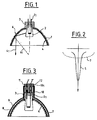
- the device shown in Figure 1 thus schematically comprises a reflector 1 and a light bulb 2 which is fixed to the focus of this reflector on its base 3.
- the pins 21 of this bulb protrude from the base and are intended to be connected to a corresponding female plug.
- the reflector 1 constitutes first of all a dichroic reflector insofar as it is made of transparent material and that it comprises, in general on its internal face, a selective reflective coating 4, which reflects visible radiation but which can be passed through by infrared heat radiation.
- the visible radiation from the bulb is thus reflected towards the front of the reflector along rays 41 and is reflected by a light beam whose distribution curve 5 ( Figure 2) is defined by the shape of the reflective surface 4 of the reflector 1.
- a support piece 6 provided, on its internal face, with a reflecting surface 6 for the heat radiation, so that this radiation, which passes through the dichroic reflector, is partly diffused by the support 6 constituting a heat exchanger and is partly reflected by this support surface 6 and to pass through the reflector again 1 and produce towards the front of this reflector, reflected rays 61 whose direction is different from that of the reflected light rays 41.
- This different direction of the spokes 61 results from the different position of the surface 6 relative to the surface 4, taking into account the position of the filament of the bulb 2.
- This direction of the rays 61 results in a distribution of the heat radiation 7 (FIG. 2) which is different from that of the visible radiation 5.
- This distribution curve will thus be spread over a large surface in front of and near the lighting device, so as to avoid undesirable thermal effects on people and illuminated objects, while of course avoiding overheating of the elements situated towards the rear of the reflector.
- the reflecting surface of the support 6 can be frosted in order to increase the diffusion of the reflected visible radiation.
- this reflecting surface 8 is produced on the internal face of a support piece 9 in the form of a cup arranged in the immediate vicinity of the external face of the reflector 1.
- This reflecting surface 8 is constituted either by a metallization of the internal face of a support piece 9 made of plastic material, or by the polished or frosted reflecting internal face of a piece 9 made of metal.
- This piece whose shape corresponds or not to that of the dichroic reflector, has in its center an opening or a housing of dimensions such that it can receive the base 3 of the dichroic reflector.
- the reflective support piece 9, constituting both a heat shield and a heat exchanger, is provided with an axial tip 10 ending in an internal flange 101.
- This rim hangs on the plug 11 comprising the female pins 12 on which the male pins 21 of the bulb 2 come to be sealed in the base 3 of the reflector 1.
- This arrangement allows the replacement of the bulb 2 and of the reflector 1 while retaining in the lighting device the reflector 9 which is automatically positioned with respect to the bulb 2 and to the reflector 1 when this bulb is placed on the plug 11.
- the axial end piece 10 in the form of lugs provided with its flange 101, will hang on a clip surrounding the plug 11.
- This support piece 9 may also, instead of being supported by the plug 11, be supported by the base 3 of the reflector 1 or by this reflector.
- the support part 1 may be fixed by its internal surface against the external face of the reflector 1.
- the reflector 1 will, in this case, be obtained by overmolding on the support 9.
- the present invention will find all its interest insofar as the lighting device is of a simple and inexpensive realization and insofar as its assembly is carried out quickly by automatically positioning the external reflector for the heat radiation on the internal reflector for visible radiation.
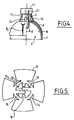
- the cup 9 forming a heat shield and a heat exchanger is produced by cutting a flat plate, preferably made of metal, which is previously coated on one of its faces, with a reflective material.
- This reflecting flat plate is cut to form radial tongues 13, for example four in number, regularly distributed around the periphery of a central part 14. These tongues 13 are cut so that by bending, the shape of the cup 9 is obtained , the edges of the tongues juxtaposing each other and against the edge of the central part 14.
- the cutting and bending are carried out so as to form between the tongues narrow openings in the form of slits resulting, as shown in 91 in Figure 1, from the non-joined assembly of the cut edges .
- This arrangement will promote the cooling of the lamp by allowing the establishment of convection currents as well as promoting the decorative effect.
- the cut tabs 13 are subject to a bending of relatively low amplitude which does not modify the structure of the reflecting surface, which makes it possible to use as starting material a metal plate previously provided with a reflecting surface in order to considerably reduce the manufacturing cost of this reflector.
- tongues 15 and 16 form two pairs of tongues, the tongues of each pair being parallel and opposite, while the tongues of one pair are perpendicular to the tongues of the other pair.
- the tongues 15 of one of the pairs are of a length such that after folding they are applied by their ends 151, possibly laterally to the base 3, but above all substantially vertically against the opposite face 111 of the base of the connection plug 11.
- the two other parallel and opposite tongues 16 are of a shorter length and have the sole function of clamping effectively, due to their shorter length, against the side wall of the base 3 in order to ensure centering. of the cup 9, while the longer tongues 15 mainly have the function of ensuring the axial positioning of the reflector 9 by pushing it axially towards the reflector 1.
Landscapes
- Engineering & Computer Science (AREA)
- General Engineering & Computer Science (AREA)
- Physics & Mathematics (AREA)
- Spectroscopy & Molecular Physics (AREA)
- Arrangement Of Elements, Cooling, Sealing, Or The Like Of Lighting Devices (AREA)
- Liquid Crystal (AREA)
- Liquid Crystal Substances (AREA)
- Control Of Eletrric Generators (AREA)
- Non-Portable Lighting Devices Or Systems Thereof (AREA)
- Vehicle Body Suspensions (AREA)
- Polarising Elements (AREA)
- Seal Device For Vehicle (AREA)
Claims (12)
- Leuchte mit einer Glühlampe, die im Inneren eines aus einem transparenten Material hergestellten Reflektors angebracht ist, der eine selektiv reflektierende Fläche (4) darbietet, mittels derer die von der Glühlampe (2) ausgesandte sichtbare Strahlung reflektierbar ist, und der für die Wärmestrahlung durchlässig ist, wobei auf der Außenseite des Reflektors eine reflektierende Fläche (6,8) für die durch den Reflektor (1) hindurchgetretene Wärmestrahlung vorgesehen ist, dadurch gekennzeichnet, daß die die Wärmestrahlung reflektierende Fläche (8) auf einem Stützelement an der Außenseite des Reflektors verwirklicht ist.
- Leuchte nach Anspruch 1, dadurch gekennzeichnet, daß das Stützelement (9) eine schalenförmige Kappe bildet, die in unmittelbarer Nachbarschaft des Reflektors angeordnet ist.
- Leuchte nach einem der vorangehenden Ansprüche, dadurch gekennzeichnet, daß das Stützelement bzw. die schalenförmige Kappe (9) von dem Reflektor getragen sind.
- Leuchte nach Anspruch 3, dadurch gekennzeichnet, daß das Stützelement bzw. die schalenförmige Kappe von einem Steckkontakt (11) getragen sind, der die Kontaktstifte (2₁) der Glühlampe (2) aufnimmt, die den Reflektor (1) für die Lichtstrahlung trägt.
- Leuchte nach Anspruch 3, dadurch gekennzeichnet, daß das Stützelement eine schalenförmige Kappe bildet, gegen deren innere die Wärmestrahlung reflektierende Fläche der Reflektor (1) für die sichtbare Strahlung festgelegt ist.
- Leuchte nach einem der Ansprüche 2 bis 5, dadurch gekennzeichnet, daß das Stützelement aus Metall besteht.
- Leuchte nach einem der vorangehenden Ansprüche, dadurch gekennzeichnet, daß die Wölbung der die Wärmestrahlung und die sichtbare Strahlung reflektierenden Flächen verschieden ist, wobei der Unterschied in der Wölbung dadurch erhalten wird, daß die die Wärmestrahlung reflektierende Fläche auf einem Stützelement (9) mit einer Wölbung ausgebildet ist, die von derjenigen des Reflektors für das sichtbare Licht abweicht.
- Leuchte nach Anspruch 6, dadurch gekennzeichnet, daß die schalenförmige Kappe (9) einstückig aus einem ebenen Metallzuschnitt hergestellt ist, dessen eine Fläche mit einer reflektierenden Beschichtung versehen ist, wobei der Zuschnitt anschließend in die Form der schalenförmigen Kappe gewölbt wird.
- Leuchte nach Anspruch 8, dadurch gekennzeichnet, daß der Zuschnitt so geschnitten wird, daß er radiale Laschen (13) bildet, die durch den Wölbungsvorgang nebeneinander zu liegen kommen.
- Leuchte nach Anspruch 8 oder 9, dadurch gekennzeichnet, daß der metallische Zuschnitt so ausgeschnitten wird, daß er radiale Laschen (13) bildet, die außenseitig über den Umfang eines zentralen Bereichs verteilt sind, der seinerseits in seinem Inneren mit ausgeschnittenen Zungen (15,16) versehen ist.
- Leuchte nach Anspruch 10, dadurch gekennzeichnet, daß die im Innern des zentralen Bereichs (14) ausgeschnittenen Zungen eine solche Länge aufweisen, daß sie mit ihrem äußeren Ende gegen die Unterseite des Steckkontakts (11) anliegen, der die Kontaktstifte (2₁) der Glühlampe (2) für den Reflektor (1) für die sichtbare Strahlung aufnimmt.
- Leuchte nach Anspruch 11, dadurch gekennzeichnet, daß die im Innern des zentralen Bereichs (14) ausgeschnittenen Zungen ein Paar von einander parallel gegenüberliegenden Zungen (15) umfassen, die eine solche Länge aufweisen, daß sie mit ihren äußeren Enden an der Unterseite (11₁) des Steckkontakts (11) zur Anlage kommen, sowie ein Paar einander parallel gegenüberliegender Zungen (16), die zu den vorgenannten Zungen senkrecht und kürzer als diese sind, so daß sie sich ausschließlich gegen den Sockel des Reflektors legen.
Applications Claiming Priority (4)
| Application Number | Priority Date | Filing Date | Title |
|---|---|---|---|
| FR9006026 | 1990-05-15 | ||
| FR909006026A FR2662235B1 (fr) | 1990-05-15 | 1990-05-15 | Dispositif d'eclairage comportant une ampoule d'eclairage disposee a l'interieur d'un reflecteur. |
| FR9104291A FR2675239B1 (fr) | 1991-04-09 | 1991-04-09 | Dispositif d'eclairage a bouclier thermique. |
| FR9104291 | 1991-04-09 |
Publications (3)
| Publication Number | Publication Date |
|---|---|
| EP0457645A2 EP0457645A2 (de) | 1991-11-21 |
| EP0457645A3 EP0457645A3 (en) | 1992-02-26 |
| EP0457645B1 true EP0457645B1 (de) | 1994-07-13 |
Family
ID=26228019
Family Applications (1)
| Application Number | Title | Priority Date | Filing Date |
|---|---|---|---|
| EP91401168A Expired - Lifetime EP0457645B1 (de) | 1990-05-15 | 1991-05-03 | Beleuchtungsvorrichtung |
Country Status (6)
| Country | Link |
|---|---|
| US (1) | US5130913A (de) |
| EP (1) | EP0457645B1 (de) |
| JP (1) | JPH04229503A (de) |
| AT (1) | ATE108532T1 (de) |
| CA (1) | CA2041906A1 (de) |
| DE (1) | DE69102819T2 (de) |
Families Citing this family (29)
| Publication number | Priority date | Publication date | Assignee | Title |
|---|---|---|---|---|
| US5798611A (en) * | 1990-10-25 | 1998-08-25 | Fusion Lighting, Inc. | Lamp having controllable spectrum |
| US6020676A (en) * | 1992-04-13 | 2000-02-01 | Fusion Lighting, Inc. | Lamp with light reflection back into bulb |
| US5323301A (en) * | 1992-12-08 | 1994-06-21 | Robert Kaufman | Dimmable studio lighting device |
| US5535110A (en) * | 1995-02-16 | 1996-07-09 | Cooper Industries, Inc. | Ceiling mounted wallwash light fixture |
| PL331378A1 (en) * | 1996-05-31 | 1999-07-05 | Fusion Lighting | Multiple-reflection electrode-free sulphur- or selenium-filled lamp and method of generating radiation using such lamp |
| US6291936B1 (en) | 1996-05-31 | 2001-09-18 | Fusion Lighting, Inc. | Discharge lamp with reflective jacket |
| US5873650A (en) * | 1996-11-19 | 1999-02-23 | Luk; John F. | Modular heat sink adapter for lamp bases |
| US6082878A (en) * | 1998-02-03 | 2000-07-04 | Cooper Industries, Inc. | Fully rotatable recessed light fixture with movable stop and adjustable length bar hanger |
| FR2782551B1 (fr) * | 1998-08-19 | 2000-11-10 | Thorn Europhane Sa | Reflecteur de luminaire d'eclairage notamment pour voie publique |
| US6227682B1 (en) | 2000-03-22 | 2001-05-08 | Cogent Light Technologies, Inc. | Coupling of light from a small light source for projection systems using parabolic reflectors |
| WO2002063390A2 (en) | 2001-02-05 | 2002-08-15 | Wavien, Inc. | An illumination engine for a projection display using a tapered light pipe |
| US6856727B2 (en) * | 2001-03-02 | 2005-02-15 | Wavien, Inc. | Coupling of light from a non-circular light source |
| US6926435B2 (en) * | 2001-08-23 | 2005-08-09 | Wavien, Inc. | Led illumination engine using a reflector |
| US20040264201A1 (en) * | 2003-06-30 | 2004-12-30 | Guide Corporation, A Delaware Corporation | Chromatic effect using light sources and condensing lenses |
| US20050247842A1 (en) * | 2004-05-10 | 2005-11-10 | Grzegorz Wronski | Hanger bar assemblies for recessed luminaires |
| US9696021B2 (en) | 2004-03-25 | 2017-07-04 | Cooper Technologies Company | Hanger bar for recessed luminaires |
| US7673841B2 (en) | 2004-03-25 | 2010-03-09 | Cooper Technologies Company | Hangar bar for recessed luminaires with integral nail |
| US20070019421A1 (en) * | 2005-07-12 | 2007-01-25 | Kregness Christopher A | Removable, multi-purpose utility light for motor vehicles |
| JP4640215B2 (ja) | 2006-02-28 | 2011-03-02 | ウシオ電機株式会社 | 光源装置 |
| US20090080189A1 (en) | 2007-09-21 | 2009-03-26 | Cooper Technologies Company | Optic Coupler for Light Emitting Diode Fixture |
| DE102008053488B4 (de) * | 2008-10-28 | 2013-04-04 | Osram Gmbh | Reflektorlampe |
| CA2768777C (en) | 2009-07-21 | 2017-11-28 | Cooper Technologies Company | Interfacing a light emitting diode (led) module to a heat sink assembly, a light reflector and electrical circuits |
| US8596837B1 (en) | 2009-07-21 | 2013-12-03 | Cooper Technologies Company | Systems, methods, and devices providing a quick-release mechanism for a modular LED light engine |
| US9060607B1 (en) | 2012-10-17 | 2015-06-23 | Cooper Technologies Company | Hanger bar for recessed light fixture mounting |
| US8939418B2 (en) | 2013-04-05 | 2015-01-27 | Cooper Technologies Company | Adjustable hanger bar for luminaires |
| US9732904B1 (en) | 2015-06-05 | 2017-08-15 | Cooper Technologies Company | Adjustable hanger bar assembly for luminaires |
| US9239131B1 (en) | 2015-06-05 | 2016-01-19 | Cooper Technologies Company | Adjustable hanger bars with detachment stop |
| US11134618B2 (en) | 2016-08-30 | 2021-10-05 | Current Lighting Solutions, Llc | Luminaire including a heat dissipation structure |
| US10584837B2 (en) | 2016-10-28 | 2020-03-10 | Cordelia Lighting, Inc. | Bar hanger system for recessed fixtures |
Family Cites Families (11)
| Publication number | Priority date | Publication date | Assignee | Title |
|---|---|---|---|---|
| US1735181A (en) * | 1927-03-30 | 1929-11-12 | Lambert L Raymond | Reflector-attaching device |
| US3322946A (en) * | 1964-11-27 | 1967-05-30 | George D Cooper | Reflector for reflecting color corrected light and heat |
| US3654455A (en) * | 1969-08-20 | 1972-04-04 | Holophane Co Inc | Luminaire |
| US3745325A (en) * | 1971-08-17 | 1973-07-10 | Eastman Kodak Co | Photographic light |
| US3769503A (en) * | 1972-06-23 | 1973-10-30 | Gen Electric | Lamp fixture having dichoric filter arrangement for selectively directing heat and light |
| FR2192272B1 (de) * | 1972-07-11 | 1975-03-07 | Cibie Projecteurs | |
| US4028542A (en) * | 1974-09-11 | 1977-06-07 | Esquire, Inc. | Faceted parabolic-type reflector system |
| DE2713615A1 (de) * | 1977-03-28 | 1978-10-05 | Patra Patent Treuhand | Baueinheit aus halogengluehlampe und reflektor |
| FR2484720A1 (fr) * | 1980-06-13 | 1981-12-18 | David Francis | Systeme de douille transformatrice a culot standard pour la conversion des luminaires |
| JPS6217904A (ja) * | 1985-07-15 | 1987-01-26 | 双葉電子工業株式会社 | 光源 |
| DE9002879U1 (de) * | 1990-03-14 | 1990-05-17 | Nafa-Light Kurt Maurer, Zumikon | Leuchte |
-
1991
- 1991-05-03 AT AT91401168T patent/ATE108532T1/de not_active IP Right Cessation
- 1991-05-03 EP EP91401168A patent/EP0457645B1/de not_active Expired - Lifetime
- 1991-05-03 DE DE69102819T patent/DE69102819T2/de not_active Expired - Fee Related
- 1991-05-07 CA CA002041906A patent/CA2041906A1/fr not_active Abandoned
- 1991-05-14 US US07/699,885 patent/US5130913A/en not_active Expired - Fee Related
- 1991-05-15 JP JP3109973A patent/JPH04229503A/ja active Pending
Also Published As
| Publication number | Publication date |
|---|---|
| CA2041906A1 (fr) | 1991-11-16 |
| EP0457645A2 (de) | 1991-11-21 |
| US5130913A (en) | 1992-07-14 |
| DE69102819D1 (de) | 1994-08-18 |
| ATE108532T1 (de) | 1994-07-15 |
| EP0457645A3 (en) | 1992-02-26 |
| DE69102819T2 (de) | 1995-02-23 |
| JPH04229503A (ja) | 1992-08-19 |
Similar Documents
| Publication | Publication Date | Title |
|---|---|---|
| EP0457645B1 (de) | Beleuchtungsvorrichtung | |
| EP0276780B1 (de) | Reflektorlampe mit einem multifunktionellen Stützelement | |
| FR2670562A1 (fr) | Dispositif d'eclairage pour vehicules. | |
| FR2813946A1 (fr) | Lampe de vehicule | |
| EP0531186A1 (de) | Signalleuchte mit elektrolumineszenten Elementen, insbesondere für Kraftfahrzeuge | |
| FR2606125A1 (fr) | Projecteur perfectionne pour vehicule automobile | |
| FR2669398A1 (fr) | Phare d'automobile. | |
| EP3016791B1 (de) | Heizmodul mit einer lampe und einer linse, befestigt an einer schiene an einem emissionsfreien teil der lampe | |
| CA1141728A (fr) | Projecteur etanche a lampe interchangeable | |
| FR2496841A1 (fr) | Lampe a reflecteur et optique profiles | |
| FR2669098A1 (fr) | Dispositif d'eclairage avec reflecteur et ampoule demontables et reglables. | |
| FR2537249A1 (fr) | Projecteur a faisceau coupe a reflecteur elliptique pour vehicule automobile | |
| FR2954458A1 (fr) | Lampe de type hublot | |
| FR2500116A1 (fr) | Projecteur d'eclairage, notamment pour vehicule automobile | |
| FR2484058A1 (fr) | Bloc optique d'eclairage, notamment pour projecteur de vehicule automobile | |
| FR2687762A1 (fr) | Projecteur a lentille equipe de moyens de montage de la lentille perfectionnes. | |
| FR2662235A1 (fr) | Dispositif d'eclairage comportant une ampoule d'eclairage disposee a l'interieur d'un reflecteur. | |
| FR2675239A1 (fr) | Dispositif d'eclairage a bouclier thermique. | |
| FR2802704A1 (fr) | Ampoule electrique a miroir et rampe d'eclairage comportant au moins une telle ampoule | |
| EP1867918B1 (de) | Scheinwerfer, der ein feststehendes, aufgesetztes Halterungselement umfasst, auf dem ein Scheinwerfer schwenkbar montiert ist | |
| EP0810400B1 (de) | Scheinwerfer, insbesondere für Kraftfahrzeuge, mit einer verbesserten mechanischen Struktur | |
| FR2565672A1 (fr) | Dispositif chauffant, notamment pour cuisiniere. | |
| EP1286110A1 (de) | Kfz-Scheinwerfer mit glatter Abdeckscheibe, und Verfahren zum Herstellen eines Teiles eines derartigen Scheinwerfers | |
| EP1544538B1 (de) | Kfz-Scheinwerfer mit einem Lampenträger | |
| FR3006744A1 (fr) | Dispositif optique, notamment pour dispositif d'eclairage et/ou de signalisation de vehicule automobile, et dispositif d'eclairage et/ou de signalisation comportant un tel dispositif |
Legal Events
| Date | Code | Title | Description |
|---|---|---|---|
| PUAI | Public reference made under article 153(3) epc to a published international application that has entered the european phase |
Free format text: ORIGINAL CODE: 0009012 |
|
| AK | Designated contracting states |
Kind code of ref document: A2 Designated state(s): AT BE CH DE DK ES GB GR IT LI LU NL SE |
|
| PUAL | Search report despatched |
Free format text: ORIGINAL CODE: 0009013 |
|
| AK | Designated contracting states |
Kind code of ref document: A3 Designated state(s): AT BE CH DE DK ES GB GR IT LI LU NL SE |
|
| 17P | Request for examination filed |
Effective date: 19920627 |
|
| 17Q | First examination report despatched |
Effective date: 19931215 |
|
| GRAA | (expected) grant |
Free format text: ORIGINAL CODE: 0009210 |
|
| AK | Designated contracting states |
Kind code of ref document: B1 Designated state(s): AT BE CH DE DK ES GB GR IT LI LU NL SE |
|
| PG25 | Lapsed in a contracting state [announced via postgrant information from national office to epo] |
Ref country code: AT Effective date: 19940713 Ref country code: IT Free format text: LAPSE BECAUSE OF FAILURE TO SUBMIT A TRANSLATION OF THE DESCRIPTION OR TO PAY THE FEE WITHIN THE PRE;WARNING: LAPSES OF ITALIAN PATENTS WITH EFFECTIVE DATE BEFORE 2007 MAY HAVE OCCURRED AT ANY TIME BEFORE 2007. THE CORRECT EFFECTIVE DATE MAY BE DIFFERENT FROM THE ONE RECORDED.SCRIBED TIME-LIMIT Effective date: 19940713 Ref country code: NL Effective date: 19940713 Ref country code: DK Effective date: 19940713 Ref country code: GR Free format text: LAPSE BECAUSE OF FAILURE TO SUBMIT A TRANSLATION OF THE DESCRIPTION OR TO PAY THE FEE WITHIN THE PRESCRIBED TIME-LIMIT Effective date: 19940713 Ref country code: ES Free format text: THE PATENT HAS BEEN ANNULLED BY A DECISION OF A NATIONAL AUTHORITY Effective date: 19940713 |
|
| REF | Corresponds to: |
Ref document number: 108532 Country of ref document: AT Date of ref document: 19940715 Kind code of ref document: T |
|
| REF | Corresponds to: |
Ref document number: 69102819 Country of ref document: DE Date of ref document: 19940818 |
|
| PG25 | Lapsed in a contracting state [announced via postgrant information from national office to epo] |
Ref country code: SE Effective date: 19941013 |
|
| GBT | Gb: translation of ep patent filed (gb section 77(6)(a)/1977) |
Effective date: 19941019 |
|
| NLV1 | Nl: lapsed or annulled due to failure to fulfill the requirements of art. 29p and 29m of the patents act | ||
| PG25 | Lapsed in a contracting state [announced via postgrant information from national office to epo] |
Ref country code: GB Effective date: 19950503 |
|
| PLBE | No opposition filed within time limit |
Free format text: ORIGINAL CODE: 0009261 |
|
| STAA | Information on the status of an ep patent application or granted ep patent |
Free format text: STATUS: NO OPPOSITION FILED WITHIN TIME LIMIT |
|
| PG25 | Lapsed in a contracting state [announced via postgrant information from national office to epo] |
Ref country code: BE Effective date: 19950531 Ref country code: CH Effective date: 19950531 Ref country code: LI Effective date: 19950531 Ref country code: LU Free format text: LAPSE BECAUSE OF NON-PAYMENT OF DUE FEES Effective date: 19950531 |
|
| 26N | No opposition filed | ||
| BERE | Be: lapsed |
Owner name: DAVID FRANCIS Effective date: 19950531 |
|
| GBPC | Gb: european patent ceased through non-payment of renewal fee |
Effective date: 19950503 |
|
| REG | Reference to a national code |
Ref country code: CH Ref legal event code: PL |
|
| PG25 | Lapsed in a contracting state [announced via postgrant information from national office to epo] |
Ref country code: DE Effective date: 19960201 |