EP0457664A1 - Vorrichtung und Verfahren zum Formen von Hohlkörpern aus thermoplastischem Werkstoff - Google Patents
Vorrichtung und Verfahren zum Formen von Hohlkörpern aus thermoplastischem Werkstoff Download PDFInfo
- Publication number
- EP0457664A1 EP0457664A1 EP91401233A EP91401233A EP0457664A1 EP 0457664 A1 EP0457664 A1 EP 0457664A1 EP 91401233 A EP91401233 A EP 91401233A EP 91401233 A EP91401233 A EP 91401233A EP 0457664 A1 EP0457664 A1 EP 0457664A1
- Authority
- EP
- European Patent Office
- Prior art keywords
- forming
- punch
- cylindrical cavity
- mold block
- gas
- Prior art date
- Legal status (The legal status is an assumption and is not a legal conclusion. Google has not performed a legal analysis and makes no representation as to the accuracy of the status listed.)
- Ceased
Links
- 238000000034 method Methods 0.000 title claims description 15
- 238000000465 moulding Methods 0.000 title abstract 8
- 239000012815 thermoplastic material Substances 0.000 title description 5
- 229920001169 thermoplastic Polymers 0.000 claims abstract description 43
- 239000004416 thermosoftening plastic Substances 0.000 claims abstract description 43
- 230000000149 penetrating effect Effects 0.000 claims abstract description 6
- 238000003856 thermoforming Methods 0.000 claims description 19
- 230000001681 protective effect Effects 0.000 claims description 10
- 238000009434 installation Methods 0.000 claims description 6
- 238000004806 packaging method and process Methods 0.000 claims description 6
- 230000002093 peripheral effect Effects 0.000 claims description 5
- 238000002347 injection Methods 0.000 claims description 3
- 239000007924 injection Substances 0.000 claims description 3
- 239000000463 material Substances 0.000 claims description 3
- 238000007493 shaping process Methods 0.000 claims description 3
- 238000004659 sterilization and disinfection Methods 0.000 claims description 3
- 229920002457 flexible plastic Polymers 0.000 claims description 2
- 229920001296 polysiloxane Polymers 0.000 claims description 2
- 230000001954 sterilising effect Effects 0.000 claims description 2
- 238000005520 cutting process Methods 0.000 description 3
- 238000010438 heat treatment Methods 0.000 description 2
- 238000005452 bending Methods 0.000 description 1
- 238000004140 cleaning Methods 0.000 description 1
- 230000001050 lubricating effect Effects 0.000 description 1
- 238000004519 manufacturing process Methods 0.000 description 1
- 238000005259 measurement Methods 0.000 description 1
- 238000012986 modification Methods 0.000 description 1
- 230000004048 modification Effects 0.000 description 1
- 230000029058 respiratory gaseous exchange Effects 0.000 description 1
- 230000001131 transforming effect Effects 0.000 description 1
- 239000002699 waste material Substances 0.000 description 1
- XLYOFNOQVPJJNP-UHFFFAOYSA-N water Substances O XLYOFNOQVPJJNP-UHFFFAOYSA-N 0.000 description 1
Images
Classifications
-
- B—PERFORMING OPERATIONS; TRANSPORTING
- B29—WORKING OF PLASTICS; WORKING OF SUBSTANCES IN A PLASTIC STATE IN GENERAL
- B29C—SHAPING OR JOINING OF PLASTICS; SHAPING OF MATERIAL IN A PLASTIC STATE, NOT OTHERWISE PROVIDED FOR; AFTER-TREATMENT OF THE SHAPED PRODUCTS, e.g. REPAIRING
- B29C51/00—Shaping by thermoforming, i.e. shaping sheets or sheet like preforms after heating, e.g. shaping sheets in matched moulds or by deep-drawing; Apparatus therefor
- B29C51/04—Combined thermoforming and prestretching, e.g. biaxial stretching
-
- B—PERFORMING OPERATIONS; TRANSPORTING
- B29—WORKING OF PLASTICS; WORKING OF SUBSTANCES IN A PLASTIC STATE IN GENERAL
- B29C—SHAPING OR JOINING OF PLASTICS; SHAPING OF MATERIAL IN A PLASTIC STATE, NOT OTHERWISE PROVIDED FOR; AFTER-TREATMENT OF THE SHAPED PRODUCTS, e.g. REPAIRING
- B29C51/00—Shaping by thermoforming, i.e. shaping sheets or sheet like preforms after heating, e.g. shaping sheets in matched moulds or by deep-drawing; Apparatus therefor
- B29C51/08—Deep drawing or matched-mould forming, i.e. using mechanical means only
-
- B—PERFORMING OPERATIONS; TRANSPORTING
- B29—WORKING OF PLASTICS; WORKING OF SUBSTANCES IN A PLASTIC STATE IN GENERAL
- B29C—SHAPING OR JOINING OF PLASTICS; SHAPING OF MATERIAL IN A PLASTIC STATE, NOT OTHERWISE PROVIDED FOR; AFTER-TREATMENT OF THE SHAPED PRODUCTS, e.g. REPAIRING
- B29C51/00—Shaping by thermoforming, i.e. shaping sheets or sheet like preforms after heating, e.g. shaping sheets in matched moulds or by deep-drawing; Apparatus therefor
- B29C51/26—Component parts, details or accessories; Auxiliary operations
- B29C51/263—Component parts, details or accessories; Auxiliary operations characterised by using a particular environment, e.g. sterile
-
- B—PERFORMING OPERATIONS; TRANSPORTING
- B29—WORKING OF PLASTICS; WORKING OF SUBSTANCES IN A PLASTIC STATE IN GENERAL
- B29C—SHAPING OR JOINING OF PLASTICS; SHAPING OF MATERIAL IN A PLASTIC STATE, NOT OTHERWISE PROVIDED FOR; AFTER-TREATMENT OF THE SHAPED PRODUCTS, e.g. REPAIRING
- B29C51/00—Shaping by thermoforming, i.e. shaping sheets or sheet like preforms after heating, e.g. shaping sheets in matched moulds or by deep-drawing; Apparatus therefor
- B29C51/10—Forming by pressure difference, e.g. vacuum
Definitions
- the present invention relates to a device for forming hollow articles such as containers, from a thermoplastic strip previously heated to a temperature suitable for thermoforming.
- a forming device is known from patent FR-2 028 281 and comprises, on the one hand, below the horizontal path of a thermoplastic strip, a mold block vertically movable between a high position for thermoforming the containers, position wherein said mold block is applied against said strip, and a low position for demolding said containers, this mold block being provided with at least one forming chamber open at its upper part and of the same internal shape as the article or container to be thermoformed, and, on the other hand, above said horizontal path, a block of counter mold either fixed or slightly movable vertically between a high position in which the lower end of the block of counter mold is slightly apart of the horizontal path of the thermoplastic strip, and a low position in which said lower end is in contact with said thermoplastic strip and clamps the latter against the upper end of the mold block in the high position, that is to say against the upper edge of each forming chamber
- a forming punch is mounted vertically movable in each cylindrical cavity with a certain lateral clearance relative to the internal face of the latter and coaxially with respect to said cavity and to the corresponding forming chamber.
- This forming punch has an upper inactive part and a lower active part, a punch whose inactive part remains in the cylindrical cavity and whose active part is capable of penetrating the corresponding forming chamber up to the vicinity of the bottom thereof and has similar dimensions but smaller than those of said forming chamber, the annular space delimited by the inner faces of the forming chamber and the cylindrical cavity, d on the one hand, and by the peripheral face of the forming punch, on the other hand, being periodically connected to a source of compressed gas.
- the active part of the forming punch is surmounted by a cylindrical inactive part with a diameter identical to that of the upper end of said active part and with a height at least equal to the vertical stroke. of said active part. Therefore, the mass to be accelerated and slowed down at the start and at the end of each descent and ascent stroke of the forming punch is large and prevents an increase in the number of strokes of said punch per unit of time.
- Another drawback of this known device lies in the fact that the inactive part of the forming punch is very long, that is to say at least equal to the height of the active part of said punch and that the volume of the space annular being located at the inactive part of the punch constitutes a large dead volume leading to unnecessary and significant consumption of compressed gas.
- annular space surrounding the shaping punch and delimited by it and the inside face of the cylindrical cavity of the counter-mold block can only be hermetically closed at the end of the downward stroke of the punch so that that the compressed gas applying a determined zone of the thermoplastic strip against the inner face of the forming chamber can be introduced into said annular space only when the punch stops at the end of the downward stroke thereof.
- the object of the present invention is to eliminate or at least reduce the drawbacks mentioned above.
- each forming punch has an axial height less than the maximum width of said punch, than each forming punch.
- a guide piston which slides in leaktight fashion in the corresponding cylindrical cavity of the counter-mold block and which the annular space located below the guide piston is capable of communicating periodically with a source of compressed gas at through at least one connecting duct.
- This new forming device is also very advantageous when used in the context of a sterile packaging installation of the type known, for example, from the German patent application DT-OS 2 754 816.
- the invention also relates to a method for forming hollow articles such as containers, from a thermoplastic strip.
- a method for forming hollow articles such as containers, from a thermoplastic strip.
- successive predetermined zones of the thermoplastic strip are preheated to the thermoforming temperature, the edge of at least one edge of at least one preheated zone of the thermoplastic strip is sandwiched between, on the one hand , the upper end of a lower mold block containing at least one forming chamber and, on the other hand, the lower end of an upper counter mold block comprising at least one cylindrical cavity which is coaxial with said forming chamber and in which is housed, with lateral play, a forming punch arranged coaxially with said forming chamber and vertically movable between a high position in which its lower end is fully retracted into said cylindrical cavity, and, a low position in which said lower end of the punch is close to the bottom of the forming chamber when the latter occupies its high thermoforming position , a hollow article is thermoformed from the zone of band enclosed on its edge,
- the object of the invention is to eliminate these drawbacks.
- This object is achieved in the context of a forming process of the aforementioned type because, before the thermoforming operation of a hollow article or container, the volume delimited by the preheated zone of enclosed thermoplastic strip is hermetically sealed. on its edge between the mold block and the counter-mold block, by the outside face of the forming punch and by the inside face of the cylindrical cavity, this volume is kept hermetically closed throughout the downward stroke of the forming punch and the pressurized gas is injected into this hermetically closed volume at the latest at the end of the downward stroke of the forming punch.
- the consumption of compressed gas is reduced and the rate of thermoforming of the containers is increased.
- the gas enclosed in the volume delimited by the guide piston, the forming punch, the zone of thermoplastic strip and the inner face of the cylindrical cavity forms a kind of lubricating film on the surface of the punch and facilitates creep and the extension of said zone by preventing the thermoplastic material from adhering to the periphery of said punch.
- a device for forming hollow articles such as containers, from a thermoplastic sheet, comprising in a guide enclosure disposed above the mold block a guide piston sliding in leaktight manner in said enclosure and surmounting the punch forming which it is integral, is known from American patent US-3,450,807 (GW Cheney).
- this known forming device belongs to a category of devices different from that of the device according to the invention because the known device cannot enclose the thermoplastic strip between the upper edge of the forming chamber provided in the mold block, and the lower edge of the guide enclosure assimilated to the cylindrical cavity of the counter-mold block of the device according to the invention, that its forming punch fully penetrates into the forming chamber during the thermoforming of a hollow article, that its guide piston is shaped as a cutting tool cooperating with the cutting edge of an annular groove formed in the upper edge of the mold block and that the outside diameter of the annular space provided between the wall of the 'guide enclosure and the forming punch and bounded upward by the guide piston is larger than the maximum diameter of the forming chamber of a container.
- the forming punch comprises below the guide piston a series of channels which are connected alternately to a vacuum source to stretch the thermoplastic sheet by bending it towards the inside of the guide enclosure and applying it against the bottom and part of the periphery of the forming punch, and to a source of compressed gas to then press this thermoplastic sheet against the side wall and the bottom of the mold block forming chamber.
- This known device does not lend itself to thermoforming of a container by the use of a forming punch and of a compressed gas, without prior stretching of the thermoplastic sheet by aspiration thereof against said punch under the action of a depression acting on the upper face of the sheet, face later constituting the internal face of the container, or by applying said sheet against said punch under the action of an overpressure acting on the underside of said sheet, face later constituting the outer face of said container.
- thermoplastic material of the enclosed sheet must be applied against the forming punch so as to completely cover its underside and its periphery before being able to use compressed gas to apply said thermoplastic material against the internal face of the forming chamber.
- the production rate of the containers is low.
- thermoplastic sheet is sandwiched between two blank clamps outside the guide enclosure and the edge of the forming chamber and the cutting of the container formed takes place inside the tightening zone of the thermoplastic sheet, the falls or waste in thermoplastic material that results from the use of the known device, are very high.
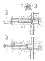
- the device 1 for forming hollow articles or containers 2 makes it possible to thermoform said containers 2 from a thermoplastic strip 3 whose path is horizontal.
- This forming device 1 is, in general, part of a packaging installation of a type known, for example, by French patent FR 2 028 765 or by German patent application DE-OS 2 754 816 and is placed immediately in downstream of a heating device 4 of the thermoplastic strip 2 advancing step by step under the heating device 4 where it is brought to the thermoforming temperature, and through the forming device 1.
- the forming device 1 comprises, below the horizontal path of the thermoplastic strip 3, a mold block 5 which is vertically movable between a high thermoforming position shown in the drawing and a low demolding position not shown in which the container 2 which has just been thermoformed and demolded can be advanced by one step and a new section of thermoplastic strip can be introduced into the forming device 1, the upper end of the mold block 5 being below the bottom of the container 2
- This mold block 5 comprises at least one forming chamber 6 open at its upper end and having an internal conformation identical to the external shape of the container 2 to be thermoformed, it being understood that the opening of said chamber 6 has a sufficient cross section to allow the demoulding of said container 2.
- Air discharge orifices 7 are provided in the mold block 5, opening into the bottom of the forming chamber 6 and connecting the latter to the atmosphere or to a vacuum pump.
- the forming device 1 further comprises, above the horizontal path of the thermoplastic strip 3, a block of counter mold 8 which is either in a fixed position or movable vertically over a short distance between, on the one hand, a low position shown in the drawing, in which it is in contact with the thermoplastic strip 3 and, in the high position of the mold block 5, clamps it against the upper edge of each forming chamber 6, and, on the other hand, an upper position slightly spaced from the horizontal path of the thermoplastic strip to facilitate advancement thereof.
- the counter-mold block 8 is provided with as many cylindrical cavities 9 as the mold block 5 has a forming chamber 6, these cavities 9 being arranged coaxially with the forming chambers 6. According to the first embodiment shown in the Figures 1 and 2, these cylindrical cavities 9 are open at both ends.
- each cylindrical cavity 9 is mounted a forming punch 10 which is coaxial with said cavity 9 and with the corresponding forming chamber 6 and which is vertically movable, for example, under the action of a control rod 11 forming part of 'a control cylinder 12 mounted on an external frame 13.
- the forming punch 10 has an upper part called inactive since it does not participate directly in the forming of container 2 as well as a lower part called active since it takes part in forming of said container 2.
- the inactive upper part of the forming punch 10 always remains inside the cylindrical cavity 9 and outside of the forming chamber 6 while the active lower part of said punch 10 is capable of penetrate vertically into the forming chamber 6 and push the zone of thermoplastic strip sandwiched on its edge between the mold block 5 and the counter-mold block 8 around the opening upper structure of said chamber 6 (see FIGS. 2 and 4).
- the inactive part of the forming punch 10 has a cross section smaller than that of the cylindrical cavity 9 and the active part of said punch 10 has similar dimensions but also smaller than those of the corresponding forming chamber 6.
- annular space 14 is delimited in each cylindrical cavity 9 by the inner face of the latter and by the peripheral face of said punch 10.
- Each forming punch 10, and more precisely said the upper inactive part thereof, is surmounted by 'A guide piston 15 which seals the upper end of the annular space 14 and whose cross section is larger than that of the punch 10 and adapted to that of the cylindrical cavity to allow said piston 15 slide tightly under the action of the control cylinder 12 and its rod 11, the lower end of which is integral with said piston 15.
- the annular space 14 is periodically connected to a source of compressed gas such as compressed air , if necessary sterile, using at least one connecting conduit 16 opening into the annular space 14 either near the lower end of the counter-mold block 8, or at the end é upper of the forming punch 10.
- a control valve not shown is interposed in the compressed gas supply circuit, if necessary sterile, between the connecting pipe 16 and the source of compressed gas.
- the inactive upper part of the forming punch 10 has an axial height less than the maximum width of said punch 10 and preferably is small enough but sufficient for the guide piston 15 to remain sufficiently spaced from the path of the thermoplastic strip 3 in the lower position of the Forming punch 10.
- the axial height of the inactive upper part of the shaping punch 10 is between one tenth and five tenths of the maximum width of said punch 10.
- connection duct (s) 16 may be formed in the guide piston 15 near the periphery of the latter so as to have axes parallel to that of the piston 15 and of the punch 10 and to lead directly into the upper end of the annular space 14.
- the control rod 11 whose lower end is fixed coaxially to the forming punch 10 on the side of the guide piston 15, opposite to said punch 10, has on its lower section a length slightly greater than the height of the cylindrical cavity 9 or that of the 10-piston punch assembly 15, a coaxial channel 17 which, at its upper end, located outside of the cylindrical cavity 9, is connected alternately to the atmosphere or to a source of compressed air by via a valve not shown.
- the connecting duct 16 formed in the guide piston 15 is aligned with the coaxial channel 17, penetrates over a small height in the inactive part of the forming punch 10 and is connected, on the one hand, to the lower end of the coaxial channel 17 and, on the other hand, at the central ends of a plurality of radial channels 18 formed horizontally in the inactive part of the forming punch 10 and opening out in the vicinity of the lower face of the piston 15 on the peripheral face forming punch 10.
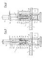
- the forming device 1 can also be used advantageously in the context of a sterile packaging installation for sterile or sterilized products, in particular in an installation of the type known by the German patent application DT-OS 2 754 816.
- the lower end of the counter-mold block 8 is mounted in leaktight manner on the sterile tunnel 19 of a packaging installation, tunnel 19, the lateral vertical walls of which cooperate with the lateral edges of the thermoplastic strip 3 so as to avoid excessive leakage of the sterile gas at slight overpressure filling the volume delimited by said tunnel 19.
- the lower end of the counter-mold block 8 enters the sterile tunnel 19 in a sealed manner.
- the cylindrical cavity 9 of the counter mold block 8 is closed, at its upper end, by a cover 20 provided with a central opening 21 in which the lower section 11a of the control rod 11.
- a cover 20 provided with a central opening 21 in which the lower section 11a of the control rod 11.
- the lower section 11a is surrounded by sealingly with a protective bellows 22 which extends from the cover 20 either to the guide piston 15 or to a place in the lower section 11a close to said piston 15.
- the lower end of the protective bellows 22 is tightly fixed either on the piston 15, or on the lower section 11a of the control rod 11 near said piston 15.
- the upper end of the protective bellows 22 is tightly fixed on the cover 20 around the central opening 21 thereof or is mounted as a seal between the upper end of the counter mold block 8 and the underside of the cover 20.
- the structure of the bellows 22 is of a known type which may include inside each bellows pleat 22a a stiffening washer 22b surrounding the lower section 11a so as to be able to slide freely along the latter.
- the annular chamber 25 provided inside the cylindrical cavity 9 and delimited by the internal face of the latter, by the external face of the protective bellows 22, by the upper face of the guide piston 15 and, where appropriate, by the free parts of the lower section 11a housed in said cavity 9, and of the lower face of the cover 20 not covered by the bellows 22, is supplied during service and is permanently filled with a sterile gas at slight overpressure relative to atmospheric pressure, this supply takes place through an inlet orifice 26 formed near the cover 20 in the side wall of the counter mold block 8 and connected to an appropriate supply circuit which makes it possible to maintain in this annular chamber 25, a slight substantially constant overpressure despite the variations in the volume of said chamber 25.
- the connecting duct or ducts 16, including the radial channels 18 opening into the annular space 14 and the coaxial channel 17, are periodically connected, outside the cylindrical cavity 9, to a source of sterile gas under pressure, by means of a control valve not shown.
- the annular chamber 25 In order to facilitate the re-sterilization and cleaning of the annular chamber 25 and of all the elements which delimit it, it can be connected to a sterilization circuit (hot water, superheated steam at high pressure) at through, on the one hand, the inlet orifice 26 and, on the other hand, an outlet orifice 27 provided in the side wall of the counter mold block 8 at a location diametrically opposite to the location of the inlet port 26 and located slightly above the guide piston 15 in the high position in which the forming punch 10 is housed entirely inside the cylindrical cavity 9 and the annular folds 22a of the bellows 22 are brought together from others and in mutual contact (Figure 3). It is advantageous to coat the forming punch 10 with a layer of flexible plastic material based on silicone. This measurement allows the punch 10 to quickly reach and maintain a constant temperature of a value close to or equal to that of the thermoplastic strip 3 at the time of thermoforming.
- a sterilization circuit hot water, superheated steam at high pressure
- thermoforming a thermoplastic container 2 using the forming device which has just been described is self-explanatory.
- a zone of thermoplastic strip 3a preheated to the thermoforming temperature is clamped on its edge between, on the one hand, the upper end of the mold block 5, the end surrounding the opening of the forming chamber 6, and, on the other hand, the lower end of the counter-mold block 8, the end surrounding the cylindrical cavity 9 inside which the forming punch 10 is then fully retracted.
- This annular space 14 varies during the thermoforming operation during the descent of the forming punch 10 and the injection of the compressed gas.
- This annular space 14 being hermetically closed during the entire downward stroke of the forming punch 10 during which the latter partially leaves the cylindrical cavity 9 and enters the forming chamber 6 as far as the bottom thereof, it is possible to inject the pressurized gas into it as soon as said space 14 is closed and it is injected therein at the latest at the end of the downward stroke of the forming piston 10. Consequently, if certain materials making up the thermoplastic strip 3 require it, can inject the gas under pressure into the hermetically sealed annular space 14, already during the downward stroke of the forming punch 10.
- the compressed gas can be injected into the annular space 14 near the upper end of the punch 10 and under the underside of piston 15 or else near the lower end of the counter-mold block 8 inside the cylindrical cavity 9 of the latter. It is advantageous to inject the compressed gas into the annular space 14 in the form of multiple gas jets and to orient them so that they do not directly strike the area of the enclosed band 3a.
- the gas is injected under pressure in the form of radial jets extending essentially in a plane perpendicular to the axis of the cylindrical cavity 9 inside thereof.
- the gas jets are oriented essentially perpendicularly either to the wall of the cylindrical cavity 9 and in the direction thereof, or to the axis of said cavity 9 and in the direction thereof.
- the gaseous jets first strike either the wall of the cavity 9 or the periphery of the forming punch 10 before being diverted towards the forming chamber 6 and on the zone of clamped band 3a.
Landscapes
- Engineering & Computer Science (AREA)
- Mechanical Engineering (AREA)
- Health & Medical Sciences (AREA)
- Toxicology (AREA)
- Blow-Moulding Or Thermoforming Of Plastics Or The Like (AREA)
Applications Claiming Priority (2)
| Application Number | Priority Date | Filing Date | Title |
|---|---|---|---|
| FR9006003A FR2661864B1 (fr) | 1990-05-14 | 1990-05-14 | Dispositif et procede de formage d'articles creux en matiere thermoplastique. |
| FR9006003 | 1990-05-14 |
Publications (1)
| Publication Number | Publication Date |
|---|---|
| EP0457664A1 true EP0457664A1 (de) | 1991-11-21 |
Family
ID=9396590
Family Applications (1)
| Application Number | Title | Priority Date | Filing Date |
|---|---|---|---|
| EP91401233A Ceased EP0457664A1 (de) | 1990-05-14 | 1991-05-14 | Vorrichtung und Verfahren zum Formen von Hohlkörpern aus thermoplastischem Werkstoff |
Country Status (5)
| Country | Link |
|---|---|
| EP (1) | EP0457664A1 (de) |
| JP (1) | JPH04229225A (de) |
| AU (1) | AU7700891A (de) |
| CA (1) | CA2042194A1 (de) |
| FR (1) | FR2661864B1 (de) |
Cited By (7)
| Publication number | Priority date | Publication date | Assignee | Title |
|---|---|---|---|---|
| FR2753125A1 (fr) * | 1996-09-06 | 1998-03-13 | Theno Jacques | Procede et dispositif de realisation par thermo-etirage- soufflage d'un recipient ou d'une forme en matiere plastique |
| WO1999044808A1 (fr) * | 1998-03-06 | 1999-09-10 | Jacques Theno | Procede et dispositif de thermo-formage, en particulier pour la fabrication d'un recipient |
| FR2796039A1 (fr) * | 1999-07-09 | 2001-01-12 | Mobile | Procede de thermoformage de pots et dispositif pour sa mise en oeuvre |
| DE10220700B4 (de) * | 2002-05-10 | 2004-04-22 | Adolf Illig Maschinenbau Gmbh & Co.Kg | Formwerkzeug zum Tiefziehen von Behältern aus thermoplastischem Kuststoff |
| DE10211125B4 (de) * | 2002-03-14 | 2004-09-30 | Adolf Illig Maschinenbau Gmbh & Co.Kg | Formwerkzeug zum Tiefziehen von Behältern aus thermoplastischem Kunststoff |
| CN111894106A (zh) * | 2020-08-11 | 2020-11-06 | 安徽兴浩建设有限公司 | 钢筋混凝土现浇圆形排水检查井轻质模板快速施工方法 |
| CN114749562A (zh) * | 2022-06-14 | 2022-07-15 | 成都飞机工业(集团)有限责任公司 | 一种超塑成形/扩散连接模具的导气系统及其制造方法 |
Families Citing this family (1)
| Publication number | Priority date | Publication date | Assignee | Title |
|---|---|---|---|---|
| DE102007050722A1 (de) * | 2007-10-22 | 2009-04-23 | Gabler Thermoform Gmbh & Co. Kg | Verfahren zum Betreiben einer Vorrichtung zum Herstellen von Formteilen aus einer thermoplastischen Kunststofffolie |
Citations (5)
| Publication number | Priority date | Publication date | Assignee | Title |
|---|---|---|---|---|
| US3450807A (en) * | 1967-06-26 | 1969-06-17 | Dow Chemical Co | Thermoplastic sheet formation |
| US3465071A (en) * | 1966-06-08 | 1969-09-02 | Illinois Tool Works | Reduced neck article forming method and apparatus |
| US3483284A (en) * | 1966-03-15 | 1969-12-09 | Monsanto Co | Method of forming plastic articles |
| US3510913A (en) * | 1966-06-08 | 1970-05-12 | Illinois Tool Works | Deep drawn article forming apparatus |
| FR2374217A1 (fr) * | 1976-12-15 | 1978-07-13 | Gatrun Anstalt | Procede et installation de conditionnement en milieu sterile |
-
1990
- 1990-05-14 FR FR9006003A patent/FR2661864B1/fr not_active Expired - Fee Related
-
1991
- 1991-05-09 CA CA 2042194 patent/CA2042194A1/en not_active Abandoned
- 1991-05-13 AU AU77008/91A patent/AU7700891A/en not_active Abandoned
- 1991-05-14 JP JP13702391A patent/JPH04229225A/ja active Pending
- 1991-05-14 EP EP91401233A patent/EP0457664A1/de not_active Ceased
Patent Citations (5)
| Publication number | Priority date | Publication date | Assignee | Title |
|---|---|---|---|---|
| US3483284A (en) * | 1966-03-15 | 1969-12-09 | Monsanto Co | Method of forming plastic articles |
| US3465071A (en) * | 1966-06-08 | 1969-09-02 | Illinois Tool Works | Reduced neck article forming method and apparatus |
| US3510913A (en) * | 1966-06-08 | 1970-05-12 | Illinois Tool Works | Deep drawn article forming apparatus |
| US3450807A (en) * | 1967-06-26 | 1969-06-17 | Dow Chemical Co | Thermoplastic sheet formation |
| FR2374217A1 (fr) * | 1976-12-15 | 1978-07-13 | Gatrun Anstalt | Procede et installation de conditionnement en milieu sterile |
Cited By (9)
| Publication number | Priority date | Publication date | Assignee | Title |
|---|---|---|---|---|
| FR2753125A1 (fr) * | 1996-09-06 | 1998-03-13 | Theno Jacques | Procede et dispositif de realisation par thermo-etirage- soufflage d'un recipient ou d'une forme en matiere plastique |
| WO1999044808A1 (fr) * | 1998-03-06 | 1999-09-10 | Jacques Theno | Procede et dispositif de thermo-formage, en particulier pour la fabrication d'un recipient |
| FR2796039A1 (fr) * | 1999-07-09 | 2001-01-12 | Mobile | Procede de thermoformage de pots et dispositif pour sa mise en oeuvre |
| DE10211125B4 (de) * | 2002-03-14 | 2004-09-30 | Adolf Illig Maschinenbau Gmbh & Co.Kg | Formwerkzeug zum Tiefziehen von Behältern aus thermoplastischem Kunststoff |
| DE10220700B4 (de) * | 2002-05-10 | 2004-04-22 | Adolf Illig Maschinenbau Gmbh & Co.Kg | Formwerkzeug zum Tiefziehen von Behältern aus thermoplastischem Kuststoff |
| CN111894106A (zh) * | 2020-08-11 | 2020-11-06 | 安徽兴浩建设有限公司 | 钢筋混凝土现浇圆形排水检查井轻质模板快速施工方法 |
| CN111894106B (zh) * | 2020-08-11 | 2021-07-20 | 安徽兴浩建设有限公司 | 钢筋混凝土现浇圆形排水检查井轻质模板快速施工方法 |
| CN114749562A (zh) * | 2022-06-14 | 2022-07-15 | 成都飞机工业(集团)有限责任公司 | 一种超塑成形/扩散连接模具的导气系统及其制造方法 |
| CN114749562B (zh) * | 2022-06-14 | 2022-10-25 | 成都飞机工业(集团)有限责任公司 | 一种超塑成形/扩散连接模具的导气系统及其制造方法 |
Also Published As
| Publication number | Publication date |
|---|---|
| FR2661864B1 (fr) | 1994-10-07 |
| CA2042194A1 (en) | 1991-11-15 |
| JPH04229225A (ja) | 1992-08-18 |
| FR2661864A1 (fr) | 1991-11-15 |
| AU7700891A (en) | 1991-11-14 |
Similar Documents
| Publication | Publication Date | Title |
|---|---|---|
| CA2293843C (fr) | Tuyere de soufflage de recipients en matiere plastique et installation pourvue d'une telle tuyere | |
| EP2595792B1 (de) | Vefahren zur herstellung eines behälters mittes blasen und befüllen | |
| FR2918916A1 (fr) | Installation pour la fabrication de recipients a partir d'une preforme et procede de commande des moyens de soufflage d'une telle installation | |
| EP0457664A1 (de) | Vorrichtung und Verfahren zum Formen von Hohlkörpern aus thermoplastischem Werkstoff | |
| EP0369888B1 (de) | Verfahren und Vorrichtung zum Sterilisieren einer Abfüllanlage für Nahrungsmittel oder pharmazeutische Produkte | |
| CH621739A5 (de) | ||
| EP1432616B1 (de) | Vorrichtung zum folienverschliessen von verpackungen in einer maschine zum konditionieren unter kontrollierter atmosphäre | |
| EP1066142B1 (de) | Einrichtung zur herstellung von latexgegenständen, wie beispielweise kissen | |
| FR2629424A1 (fr) | Recipient thermoplastique et procede de fabrication d'un tel recipient | |
| FR2525559A1 (fr) | Procede et dispositif pour la production d'un emballage | |
| EP1915295B1 (de) | Inertisierungsmittel mit niedriger geschwindigkeit und vorrichtung zur verwendung des inertisierungsmittels zur verpackung eines lebensmittelproduktes | |
| CH426236A (fr) | Procédé pour la fabrication d'un récipient muni d'un revêtement extérieur, appareil d'extrusion pour la mise en oeuvre de ce procédé, et récipient obtenu par ce procédé | |
| EP3573891B1 (de) | Verfahren zur herstellung einer vorrichtung zur abgabe eines produkts | |
| EP0069007B1 (de) | Verfahren zur Herstellung von gestreckten und geblasenen Kunststoffbehältern und Vorrichtung zur Durchführung des Verfahrens | |
| CH678416A5 (de) | ||
| EP1063077B1 (de) | Verfahren zum Herstellen von Verpackungen und dazugehörende Vorrichtung | |
| FR2598959A1 (fr) | Procede et dispositif d'injection de pastisol liquide sous faible pression | |
| CH345260A (fr) | Procédé de mise en récipients stériles dans des conditions stériles d'un produit préalabement stérilisé et installation pour la mise en oeuvre du procédé | |
| FR2763561A1 (fr) | Systeme de gonflage sterile pour un sac a paroi souple ferme | |
| FR2597833A1 (fr) | Procede et dispositif pour le thermoscellage de barquettes a atmosphere interne gazeuse | |
| EP0734971B1 (de) | Warmgeformter Kunststoffbehälter, z.B. für Nahrungsmittel, sowie Vorrichtung zu seiner Herstellung | |
| EP0391854A1 (de) | Verfahren zur Herstellung von dünnwandigen thermoplastischen Gegenständen und Vorrichtung zur Durchführung des Verfahrens | |
| EP1562827B1 (de) | Vorrichtung zum folienverschliessen von verpackungen in einer maschine zum konditionieren unter kontrollierter atmosphäre | |
| CH605275A5 (en) | Food container forming filling and closing machine | |
| CH619408A5 (en) | Method for packaging in a sterile environment and installation for implementing the method |
Legal Events
| Date | Code | Title | Description |
|---|---|---|---|
| PUAI | Public reference made under article 153(3) epc to a published international application that has entered the european phase |
Free format text: ORIGINAL CODE: 0009012 |
|
| AK | Designated contracting states |
Kind code of ref document: A1 Designated state(s): CH DE ES FR GB IT LI |
|
| 17P | Request for examination filed |
Effective date: 19920217 |
|
| RAP1 | Party data changed (applicant data changed or rights of an application transferred) |
Owner name: JAGENBERG AKTIENGESELLSCHAFT |
|
| 17Q | First examination report despatched |
Effective date: 19930813 |
|
| 111L | Licence recorded |
Free format text: 0100 E.R.C.A. (ETUDE ET REALISATION DE CHAINES AUTOMATIQUES),S.A. |
|
| STAA | Information on the status of an ep patent application or granted ep patent |
Free format text: STATUS: THE APPLICATION HAS BEEN REFUSED |
|
| 18R | Application refused |
Effective date: 19950608 |