EP0457750B1 - Moteur à combustion interne à refroidissement liquide - Google Patents
Moteur à combustion interne à refroidissement liquide Download PDFInfo
- Publication number
- EP0457750B1 EP0457750B1 EP91890092A EP91890092A EP0457750B1 EP 0457750 B1 EP0457750 B1 EP 0457750B1 EP 91890092 A EP91890092 A EP 91890092A EP 91890092 A EP91890092 A EP 91890092A EP 0457750 B1 EP0457750 B1 EP 0457750B1
- Authority
- EP
- European Patent Office
- Prior art keywords
- dynamo
- cap
- internal combustion
- combustion engine
- cover
- Prior art date
- Legal status (The legal status is an assumption and is not a legal conclusion. Google has not performed a legal analysis and makes no representation as to the accuracy of the status listed.)
- Expired - Lifetime
Links
- 238000002485 combustion reaction Methods 0.000 title claims description 11
- 239000000110 cooling liquid Substances 0.000 title claims 2
- 239000010687 lubricating oil Substances 0.000 claims description 9
- 238000007789 sealing Methods 0.000 claims description 6
- 239000002184 metal Substances 0.000 claims 2
- 239000002826 coolant Substances 0.000 description 4
- 230000005855 radiation Effects 0.000 description 4
- 239000003921 oil Substances 0.000 description 3
- 239000004636 vulcanized rubber Substances 0.000 description 3
- 230000005540 biological transmission Effects 0.000 description 1
- 239000002775 capsule Substances 0.000 description 1
- 238000010276 construction Methods 0.000 description 1
- 230000007812 deficiency Effects 0.000 description 1
- 238000005538 encapsulation Methods 0.000 description 1
- 230000005284 excitation Effects 0.000 description 1
- 230000002349 favourable effect Effects 0.000 description 1
- 238000012423 maintenance Methods 0.000 description 1
- 238000004519 manufacturing process Methods 0.000 description 1
- 239000000203 mixture Substances 0.000 description 1
- 238000001228 spectrum Methods 0.000 description 1
Images

Classifications
-
- F—MECHANICAL ENGINEERING; LIGHTING; HEATING; WEAPONS; BLASTING
- F02—COMBUSTION ENGINES; HOT-GAS OR COMBUSTION-PRODUCT ENGINE PLANTS
- F02B—INTERNAL-COMBUSTION PISTON ENGINES; COMBUSTION ENGINES IN GENERAL
- F02B77/00—Component parts, details or accessories, not otherwise provided for
- F02B77/11—Thermal or acoustic insulation
- F02B77/13—Acoustic insulation
-
- F—MECHANICAL ENGINEERING; LIGHTING; HEATING; WEAPONS; BLASTING
- F02—COMBUSTION ENGINES; HOT-GAS OR COMBUSTION-PRODUCT ENGINE PLANTS
- F02B—INTERNAL-COMBUSTION PISTON ENGINES; COMBUSTION ENGINES IN GENERAL
- F02B67/00—Engines characterised by the arrangement of auxiliary apparatus not being otherwise provided for, e.g. the apparatus having different functions; Driving auxiliary apparatus from engines, not otherwise provided for
-
- F—MECHANICAL ENGINEERING; LIGHTING; HEATING; WEAPONS; BLASTING
- F02—COMBUSTION ENGINES; HOT-GAS OR COMBUSTION-PRODUCT ENGINE PLANTS
- F02B—INTERNAL-COMBUSTION PISTON ENGINES; COMBUSTION ENGINES IN GENERAL
- F02B75/00—Other engines
- F02B75/02—Engines characterised by their cycles, e.g. six-stroke
- F02B2075/022—Engines characterised by their cycles, e.g. six-stroke having less than six strokes per cycle
- F02B2075/025—Engines characterised by their cycles, e.g. six-stroke having less than six strokes per cycle two
Definitions
- the invention relates to a liquid-cooled internal combustion engine with a piston-controlled outlet, in particular a two-stroke internal combustion engine, which is equipped with an alternator or an alternator and a lubricating oil pump and in which the cylinder head has a cap which seals against it and forms the coolant space, avoiding metallic contact the cylinder extends approximately to the outlet and has a crank-side cap sealing surface.
- the invention is therefore based on the object of eliminating these deficiencies and reducing the vibration excitation by the frequency spectrum of the internal combustion engine to a minimum or largely preventing the transmission of structure-borne noise.
- the invention solves this problem in that both the lubricating oil pump and the alternator are provided with lids which, like the cap, are interposed with soft seals and avoid metallic contact on the crank or machine housing, the Have the cap and the cover for the lubricating oil pump tightened collar screws for their attachment, between whose head and the cap or the cover a washer with a vulcanized rubber layer is inserted.
- the cap and the cover for the lubricating oil pump are fastened with collar screws tightened to the stop, between the screw head and the cap or the cover the washers are inserted with a vulcanized rubber layer, so that on the one hand a reliable attachment of the cap or the achieved a lid and on the other hand metallic contact is avoided. Since these are collar screws, they can only be tightened to a certain extent, which prevents the soft seals from being pressed together too strongly. However, there is no metallic contact, because between the screw head and the cap or the cover, the washer is arranged. When adjusting the rubber hardness, care must of course be taken to ensure that the sealing function remains guaranteed.
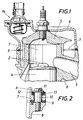
- the cylinder 1 of a two-stroke internal combustion engine has overflow channels 2 for the fuel-air mixture and an outlet channel 3, the slots of these channels being controlled by the piston 4.
- the upper part of the cylinder 1 or the cylinder head 5 are water-cooled, the cylinder head 5 being a coolant chamber which is sealed off from it has forming cap 6, which extends approximately over the cylinder 1 to the outlet 3 and has a crank-side cap sealing surface 7.
- a soft seal 9 is provided between the cap sealing surface 7 and the engine or crankcase 8.
- collar screws 10 for fastening the cap 6 to the housing 8 are collar screws 10 (Fig.
- a washer 12 is inserted with vulcanized rubber layer 13, so that any metallic Contact between the cap 6 and the housing 8 or the fastening screw 10 is avoided.
- a thermostat is designated, which has no inventive significance.
- a cover 16 is also provided for the lubricating oil pump 15, which rests on the crankcase 8 via a soft seal 9 and has a maintenance opening 18 which can be closed by a further cover 17.
- the cover 16 is attached to the crankcase 8 in the manner shown in FIG. 2.
- the oil pump 15 is not attached to the cover 16, but on a support 20 held by arms 19 of the crankcase 8, so that the required distance of the oil pump drive gear 21 from the crankshaft 22 remains constant.
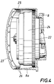
- the cover 23 for the alternator 24 terminates in a connection piece 25 with which the cover 23 in the cylindrical housing part 8a of the crankcase 8 for the alternator 24 with the interposition of O-rings 26 is inserted without screws.
Landscapes
- Engineering & Computer Science (AREA)
- Physics & Mathematics (AREA)
- Acoustics & Sound (AREA)
- Chemical & Material Sciences (AREA)
- Combustion & Propulsion (AREA)
- Mechanical Engineering (AREA)
- General Engineering & Computer Science (AREA)
- Cylinder Crankcases Of Internal Combustion Engines (AREA)
- Lubrication Of Internal Combustion Engines (AREA)
- Lubrication Details And Ventilation Of Internal Combustion Engines (AREA)
- Gasket Seals (AREA)
Claims (2)
- Moteur à combustion interne à refroidissement par liquide, avec un échappement commandé par le piston, en particulier moteur à combustion interne à deux temps, équipé d'une génératrice d'éclairage et d'allumage (24), ainsi que d'une pompe à huile de lubrification (15), et dans lequel la culasse (5) comporte un capuchon (6) formant l'enceinte destinée au liquide de refroidissement, appliqué contre elle de façon étanche mais en évitant tout contact métallique, passant sur le cylindre (1) en arrivant à peu près jusqu'à l'échappement (3) et présentant une surface d'étanchéité de capuchon (7), côté vilebrequin,
caractérisé en ce que tant la pompe à huile de lubrification (15) qu'également la génératrice d'éclairage et d'allumage (24) sont pourvues de couvercles (16, 17; 23), maintenus, tout comme le capuchon (6), sur sa surface d'étanchéité (7), avec interposition de joints d'étanchéité souples (9; 26) et en évitant tout contact métallique sur le carter de vilebrequin ou le carter moteur (8; 8a), le capuchon (6) et le couvercle (16, 17) destiné à la pompe à huile de lubrification (15) comportant pour leur fixation des vis à embase (10) serrées sur une butée, une rondelle de garniture (12) dotée d'une couche en caoutchouc (13) vulcanisée étant insérée entre la tête (11) des vis et le capuchon (6). - Moteur à combustion interne selon la revendication 1, caractérisé en ce que le couvercle (23) destiné à la génératrice d'éclairage et d'allumage (24) se transforme en une tubulure (25), à l'aide de laquelle il est enfiché, sans vissage, dans la partie de carter (8a) cylindrique destinée à la génératrice d'éclairage et d'allumage (24), avec interposition de joints toriques (26).
Applications Claiming Priority (2)
| Application Number | Priority Date | Filing Date | Title |
|---|---|---|---|
| AT1086/90 | 1990-05-16 | ||
| AT0108690A ATA108690A (de) | 1990-05-16 | 1990-05-16 | Flüssigkeitsgekühlte brennkraftmaschine |
Publications (2)
| Publication Number | Publication Date |
|---|---|
| EP0457750A1 EP0457750A1 (fr) | 1991-11-21 |
| EP0457750B1 true EP0457750B1 (fr) | 1993-12-15 |
Family
ID=3506285
Family Applications (1)
| Application Number | Title | Priority Date | Filing Date |
|---|---|---|---|
| EP91890092A Expired - Lifetime EP0457750B1 (fr) | 1990-05-16 | 1991-04-29 | Moteur à combustion interne à refroidissement liquide |
Country Status (6)
| Country | Link |
|---|---|
| US (1) | US5241934A (fr) |
| EP (1) | EP0457750B1 (fr) |
| JP (1) | JPH04228862A (fr) |
| AT (1) | ATA108690A (fr) |
| DE (1) | DE59100715D1 (fr) |
| ES (1) | ES2048005T3 (fr) |
Families Citing this family (3)
| Publication number | Priority date | Publication date | Assignee | Title |
|---|---|---|---|---|
| US6491014B1 (en) * | 2000-08-30 | 2002-12-10 | Keith Eickert | Valve cover assembly for internal combustion engine |
| JP3943972B2 (ja) * | 2002-03-19 | 2007-07-11 | 本田技研工業株式会社 | エンジンのケーシング |
| JP6055505B2 (ja) * | 2015-03-31 | 2016-12-27 | 富士重工業株式会社 | エンジン |
Family Cites Families (9)
| Publication number | Priority date | Publication date | Assignee | Title |
|---|---|---|---|---|
| AT121814B (de) * | 1928-11-06 | 1931-03-10 | Climax Motorenwerke Und Schiff | Mehrzylindrige Brennkraftmaschine. |
| US3926157A (en) * | 1973-10-12 | 1975-12-16 | Bombardier Ltd | Two-cycle engine with inlet porting by rotary valve |
| GB1582148A (en) * | 1976-05-12 | 1980-12-31 | Deere & Co | Vibration isolation assembly |
| US4066058A (en) * | 1976-05-12 | 1978-01-03 | Deere & Company | Vibration isolation system |
| AT387624B (de) * | 1981-03-31 | 1989-02-27 | Steyr Daimler Puch Ag | Hubkolben-brennkraftmaschine |
| DE3519205A1 (de) * | 1985-05-29 | 1986-12-04 | Dr.Ing.H.C. F. Porsche Ag, 7000 Stuttgart | Befestigung einer abdeckhaube an einem zylinderkopf |
| DE3637890A1 (de) * | 1985-11-06 | 1987-05-14 | Steyr Daimler Puch Ag | Fluessigkeitsgekuehlte brennkraftmaschine mit kolbengesteuertem auslass, insbesondere zweitakt-brennkraftmaschine |
| US4667628A (en) * | 1986-03-06 | 1987-05-26 | General Motors Corporation | Oil pan isolation mounting and seal |
| US4719892A (en) * | 1986-06-26 | 1988-01-19 | General Motors Corporation | Cavity closure with isolator seal and method |
-
1990
- 1990-05-16 AT AT0108690A patent/ATA108690A/de not_active IP Right Cessation
-
1991
- 1991-04-29 EP EP91890092A patent/EP0457750B1/fr not_active Expired - Lifetime
- 1991-04-29 ES ES91890092T patent/ES2048005T3/es not_active Expired - Lifetime
- 1991-04-29 DE DE91890092T patent/DE59100715D1/de not_active Expired - Fee Related
- 1991-05-10 US US07/698,459 patent/US5241934A/en not_active Expired - Fee Related
- 1991-05-10 JP JP3199767A patent/JPH04228862A/ja active Pending
Also Published As
| Publication number | Publication date |
|---|---|
| JPH04228862A (ja) | 1992-08-18 |
| EP0457750A1 (fr) | 1991-11-21 |
| ES2048005T3 (es) | 1994-03-01 |
| DE59100715D1 (de) | 1994-01-27 |
| ATA108690A (de) | 1994-12-15 |
| US5241934A (en) | 1993-09-07 |
Similar Documents
| Publication | Publication Date | Title |
|---|---|---|
| DE1914162C3 (de) | Luftgekühlte Einzylinderbrennkraftm aschine | |
| DE1301655C2 (de) | Brennkraftmaschine mit fluessigkeitsgekuehlten Zylinderlaufbuchsen | |
| DE2628692A1 (de) | Schalldaemmender deckel fuer motorengehaeuse, insbesondere zylinderkopfhaube | |
| DE2920082C2 (de) | Brennkraftmaschine mit körperschallisolierendem Element zwischen Triebwerksträger und Kurbelgehäuse | |
| EP0695866A1 (fr) | Bloc cylindre pour moteur à combustion interne avec chemises d'eau en aluminium | |
| EP0457750B1 (fr) | Moteur à combustion interne à refroidissement liquide | |
| DE2801431A1 (de) | Hubkolben-brennkraftmaschine | |
| DE2143734B2 (de) | Brennkraftmaschine mit einem in den Durchgang fur das Kuhlwasser zwischen Zylinderkopf und Kurbeigehause einge setzten Zwischenrohr | |
| DE2920081A1 (de) | Brennkraftmaschine | |
| DE4004767A1 (de) | Lagerhuelse | |
| DE4242265C1 (de) | Ventilhaubendeckel | |
| EP0062030A1 (fr) | Moteur à combustion interne à piston alternatif | |
| DE2547992A1 (de) | Zylinderkopf fuer brennkraftmaschinen mit verdichtungszuendung | |
| DE3439534C2 (de) | Rüttelstampfer | |
| DE2917339A1 (de) | Steuerraederkasten fuer brennkraftmaschinen | |
| EP0435847B1 (fr) | Moteur alternatif à combustion interne | |
| DE720953C (de) | Kurbelwellenabdichtung fuer Brennkraftmaschinen | |
| DE3229561A1 (de) | Brennkraftmaschine | |
| AT347185B (de) | Raederkasten fuer brennkraftmaschinen | |
| DE3335983C2 (de) | Brennkraftmaschine | |
| DE19755107B4 (de) | Brennkraftmaschine | |
| DE3637890A1 (de) | Fluessigkeitsgekuehlte brennkraftmaschine mit kolbengesteuertem auslass, insbesondere zweitakt-brennkraftmaschine | |
| DE2908735A1 (de) | Zylinderblock und kurbelgehaeuse fuer eine fluessigkeitsgekuehlte brennkraftmaschine | |
| DE4039190C1 (en) | Crankcase gasket for vehicle IC engine - has shaped seal to fit around flanges on cylinder block and bump | |
| DE4401486A1 (de) | Gehäusedeckel |
Legal Events
| Date | Code | Title | Description |
|---|---|---|---|
| PUAI | Public reference made under article 153(3) epc to a published international application that has entered the european phase |
Free format text: ORIGINAL CODE: 0009012 |
|
| AK | Designated contracting states |
Kind code of ref document: A1 Designated state(s): CH DE ES FR GB IT LI SE |
|
| 17P | Request for examination filed |
Effective date: 19911021 |
|
| 17Q | First examination report despatched |
Effective date: 19930115 |
|
| GRAA | (expected) grant |
Free format text: ORIGINAL CODE: 0009210 |
|
| AK | Designated contracting states |
Kind code of ref document: B1 Designated state(s): CH DE ES FR GB IT LI SE |
|
| REF | Corresponds to: |
Ref document number: 59100715 Country of ref document: DE Date of ref document: 19940127 |
|
| PGFP | Annual fee paid to national office [announced via postgrant information from national office to epo] |
Ref country code: SE Payment date: 19940222 Year of fee payment: 4 |
|
| GBT | Gb: translation of ep patent filed (gb section 77(6)(a)/1977) |
Effective date: 19940126 |
|
| REG | Reference to a national code |
Ref country code: ES Ref legal event code: FG2A Ref document number: 2048005 Country of ref document: ES Kind code of ref document: T3 |
|
| ITF | It: translation for a ep patent filed | ||
| ET | Fr: translation filed | ||
| PGFP | Annual fee paid to national office [announced via postgrant information from national office to epo] |
Ref country code: ES Payment date: 19940321 Year of fee payment: 4 |
|
| PGFP | Annual fee paid to national office [announced via postgrant information from national office to epo] |
Ref country code: DE Payment date: 19940324 Year of fee payment: 4 |
|
| PGFP | Annual fee paid to national office [announced via postgrant information from national office to epo] |
Ref country code: FR Payment date: 19940330 Year of fee payment: 4 |
|
| PGFP | Annual fee paid to national office [announced via postgrant information from national office to epo] |
Ref country code: CH Payment date: 19940422 Year of fee payment: 4 |
|
| PLBE | No opposition filed within time limit |
Free format text: ORIGINAL CODE: 0009261 |
|
| STAA | Information on the status of an ep patent application or granted ep patent |
Free format text: STATUS: NO OPPOSITION FILED WITHIN TIME LIMIT |
|
| 26N | No opposition filed | ||
| EAL | Se: european patent in force in sweden |
Ref document number: 91890092.9 |
|
| PG25 | Lapsed in a contracting state [announced via postgrant information from national office to epo] |
Ref country code: GB Effective date: 19950429 |
|
| PG25 | Lapsed in a contracting state [announced via postgrant information from national office to epo] |
Ref country code: SE Effective date: 19950430 Ref country code: LI Effective date: 19950430 Ref country code: CH Effective date: 19950430 |
|
| PG25 | Lapsed in a contracting state [announced via postgrant information from national office to epo] |
Ref country code: ES Free format text: LAPSE BECAUSE OF NON-PAYMENT OF DUE FEES Effective date: 19950503 |
|
| REG | Reference to a national code |
Ref country code: CH Ref legal event code: PL |
|
| PG25 | Lapsed in a contracting state [announced via postgrant information from national office to epo] |
Ref country code: FR Effective date: 19951229 |
|
| GBPC | Gb: european patent ceased through non-payment of renewal fee |
Effective date: 19950429 |
|
| PG25 | Lapsed in a contracting state [announced via postgrant information from national office to epo] |
Ref country code: DE Effective date: 19960103 |
|
| EUG | Se: european patent has lapsed |
Ref document number: 91890092.9 |
|
| REG | Reference to a national code |
Ref country code: FR Ref legal event code: ST |
|
| REG | Reference to a national code |
Ref country code: ES Ref legal event code: FD2A Effective date: 20010503 |
|
| PG25 | Lapsed in a contracting state [announced via postgrant information from national office to epo] |
Ref country code: IT Free format text: LAPSE BECAUSE OF NON-PAYMENT OF DUE FEES Effective date: 20050429 |