EP0457762B1 - Stellantrieb - Google Patents
Stellantrieb Download PDFInfo
- Publication number
- EP0457762B1 EP0457762B1 EP89913080A EP89913080A EP0457762B1 EP 0457762 B1 EP0457762 B1 EP 0457762B1 EP 89913080 A EP89913080 A EP 89913080A EP 89913080 A EP89913080 A EP 89913080A EP 0457762 B1 EP0457762 B1 EP 0457762B1
- Authority
- EP
- European Patent Office
- Prior art keywords
- servo
- housing wall
- drive according
- magnetic
- piston
- Prior art date
- Legal status (The legal status is an assumption and is not a legal conclusion. Google has not performed a legal analysis and makes no representation as to the accuracy of the status listed.)
- Expired - Lifetime
Links
- 239000004020 conductor Substances 0.000 claims abstract description 46
- 230000004907 flux Effects 0.000 claims abstract description 22
- 230000001681 protective effect Effects 0.000 claims description 17
- 229910000831 Steel Inorganic materials 0.000 claims description 5
- 239000010959 steel Substances 0.000 claims description 5
- 239000011810 insulating material Substances 0.000 claims description 3
- 239000000463 material Substances 0.000 abstract description 3
- 239000000523 sample Substances 0.000 description 8
- 238000011156 evaluation Methods 0.000 description 3
- 229910052751 metal Inorganic materials 0.000 description 3
- 239000002184 metal Substances 0.000 description 3
- 238000000034 method Methods 0.000 description 2
- 230000035699 permeability Effects 0.000 description 2
- 229910000906 Bronze Inorganic materials 0.000 description 1
- 229910052782 aluminium Inorganic materials 0.000 description 1
- XAGFODPZIPBFFR-UHFFFAOYSA-N aluminium Chemical compound [Al] XAGFODPZIPBFFR-UHFFFAOYSA-N 0.000 description 1
- 239000010974 bronze Substances 0.000 description 1
- KUNSUQLRTQLHQQ-UHFFFAOYSA-N copper tin Chemical compound [Cu].[Sn] KUNSUQLRTQLHQQ-UHFFFAOYSA-N 0.000 description 1
- 230000002349 favourable effect Effects 0.000 description 1
- -1 ferrous metals Chemical class 0.000 description 1
- 238000009434 installation Methods 0.000 description 1
- 230000002787 reinforcement Effects 0.000 description 1
Images

Classifications
-
- F—MECHANICAL ENGINEERING; LIGHTING; HEATING; WEAPONS; BLASTING
- F15—FLUID-PRESSURE ACTUATORS; HYDRAULICS OR PNEUMATICS IN GENERAL
- F15B—SYSTEMS ACTING BY MEANS OF FLUIDS IN GENERAL; FLUID-PRESSURE ACTUATORS, e.g. SERVOMOTORS; DETAILS OF FLUID-PRESSURE SYSTEMS, NOT OTHERWISE PROVIDED FOR
- F15B15/00—Fluid-actuated devices for displacing a member from one position to another; Gearing associated therewith
- F15B15/20—Other details, e.g. assembly with regulating devices
- F15B15/28—Means for indicating the position, e.g. end of stroke
- F15B15/2815—Position sensing, i.e. means for continuous measurement of position, e.g. LVDT
- F15B15/2861—Position sensing, i.e. means for continuous measurement of position, e.g. LVDT using magnetic means
-
- G—PHYSICS
- G01—MEASURING; TESTING
- G01D—MEASURING NOT SPECIALLY ADAPTED FOR A SPECIFIC VARIABLE; ARRANGEMENTS FOR MEASURING TWO OR MORE VARIABLES NOT COVERED IN A SINGLE OTHER SUBCLASS; TARIFF METERING APPARATUS; MEASURING OR TESTING NOT OTHERWISE PROVIDED FOR
- G01D5/00—Mechanical means for transferring the output of a sensing member; Means for converting the output of a sensing member to another variable where the form or nature of the sensing member does not constrain the means for converting; Transducers not specially adapted for a specific variable
- G01D5/12—Mechanical means for transferring the output of a sensing member; Means for converting the output of a sensing member to another variable where the form or nature of the sensing member does not constrain the means for converting; Transducers not specially adapted for a specific variable using electric or magnetic means
- G01D5/14—Mechanical means for transferring the output of a sensing member; Means for converting the output of a sensing member to another variable where the form or nature of the sensing member does not constrain the means for converting; Transducers not specially adapted for a specific variable using electric or magnetic means influencing the magnitude of a current or voltage
- G01D5/142—Mechanical means for transferring the output of a sensing member; Means for converting the output of a sensing member to another variable where the form or nature of the sensing member does not constrain the means for converting; Transducers not specially adapted for a specific variable using electric or magnetic means influencing the magnitude of a current or voltage using Hall-effect devices
- G01D5/145—Mechanical means for transferring the output of a sensing member; Means for converting the output of a sensing member to another variable where the form or nature of the sensing member does not constrain the means for converting; Transducers not specially adapted for a specific variable using electric or magnetic means influencing the magnitude of a current or voltage using Hall-effect devices influenced by the relative movement between the Hall device and magnetic fields
Definitions
- the invention relates to an actuator with an actuator movable behind a housing wall, to which a device for generating a magnetic field is attached, and a magnetic field sensor that can be attached in front of the housing wall.
- pneumatic actuators of the type mentioned at the beginning so-called pneumatic cylinders
- pneumatic cylinders have a piston which can reciprocate inside a cylinder wall and which is connected to a piston rod emerging from the end face of the cylinder.
- the cylinder wall in the known pneumatic cylinders is usually made of non-ferrous metals, e.g. B. bronze, aluminum or the like.
- a permanent magnet is provided on the piston of the pneumatic cylinder, the north pole-south pole axis of which is essentially perpendicular to the cylinder wall. The field lines generated by the permanent magnet can emerge through the cylinder wall essentially unhindered.
- a Hall probe is provided on the outside of the cylinder wall, which is influenced by the magnetic field of the permanent magnet when the piston is in a predetermined position. In this way it is possible to detect the piston position of the pneumatic cylinder in order to control the movement of the pneumatic cylinder or to switch off the pneumatic cylinder at a predetermined piston position.
- hydraulic high-pressure cylinders are now used in practice. Their area of application ranges from lifting platforms to rail laying vehicles, etc. The installation location of such hydraulic high-pressure cylinders is often very cramped. Nevertheless, there is a need to be able to detect the piston position even with hydraulic high-pressure cylinders.
- the cylinder wall in hydraulic high-pressure cylinders is mostly made of steel. Steel is a magnetically conductive material and would therefore shield the magnetic field of a permanent magnet arranged on the piston from the outside.
- the wall thicknesses of the hydraulic high-pressure cylinders are relatively large due to the enormous working pressures, so that there is no longer a magnetic field sufficient for reliable control to be located on the outside of the cylinder wall.
- the housing wall is made of a magnetically conductive material, in which field lines of the magnetic field in the housing wall form a main flow shielded from the front of the housing wall, and that at least one for generating a magnetic secondary flow on the front of the housing wall , Two ends having a magnetic conductor is arranged, the first end of which is adjacent to the housing wall, and the second end of which delimits an air gap into which the magnetic field sensor is attached.
- two magnetic conductors are provided, the second ends of which are arranged opposite one another to form the air gap.
- This solution enables the position of the actuator to be detected in a simple manner even in the case of actuators with a magnetically shielding housing wall.
- the magnetic field generated behind the housing wall is deflected by the magnetically shielding material, which is always also a magnetically conductive material, so that the main magnetic flux inevitably forms in the housing wall without the field lines emerging from the front of the housing wall.
- the magnetic conductors are each adjacent to one end of the housing wall, the main flow formed in the housing wall divides by splitting a secondary flow migrating into the magnetic conductors, so that a magnetic field also exists in the air gap between the two second ends of the magnetic conductors is produced.
- a magnetic field sensor arranged in this air gap detects the changes in the magnetic field generated there in each case as a function of the position of the actuator.
- the actuator is designed as a hydraulic high-pressure cylinder with a piston connected to a piston rod as an actuator, the cylinder wall forming the housing wall. Because precisely with such hydraulic high-pressure cylinders, the solution according to the invention enables the otherwise quite complex Detecting the piston position in a particularly simple manner, the invention making use of the fact that the cylinder wall consists of a magnetically shielding material.
- the device for generating a magnetic field is designed as a magnet, in particular a permanent magnet.
- the training as a permanent magnet has the advantage that no electrical connections have to be made inside the actuator.
- the two magnetic conductors can be attached particularly flat to the housing wall of the actuator if the second ends of the magnetic conductors overlap to form the air gap, so that the magnetic conductors and the magnetic field sensor form a bridge.
- This bridge can be very flat due to the overlapping ends of the magnetic conductors.
- the height of the bridge is determined by the thickness of the magnetic conductors and the magnetic field sensor, which is usually a Hall probe.
- the bridge is arranged in a protective housing which can be attached to the high-pressure cylinder with a holder at a predetermined location.
- the protective housing serves to protect the bridge from external influences.
- the tributary branched off by the magnetic conductors can be easily increased in that the magnetic conductors are made of dynamo sheet.
- This dynamo sheet already has an increased permeability compared to normal sheet metal.
- the magnetic conductors are made of sheet metal with a grain-oriented preferred direction, since this sheet is characterized by permeability that is even higher than that of dynamo sheets.
- the reinforcement of the secondary flow which forms in the magnetic conductors also contributes favorably if the distance between the first ends of the two magnetic conductors is less than or equal to the length of the main magnetic flux in the magnetically shielding housing wall.
- the length of the main magnetic flux in the magnetically shielding housing wall is essentially determined by the arrangement of the magnets provided on the actuator. This length therefore remains the same for the actuating cylinder to be considered regardless of the position of the actuator. Moving the actuator only shifts the location, but not the length of the main magnetic flux formed in the housing wall.
- the bridge with the magnetic field sensor can be particularly easily on the outside of the actuator or Attach the actuating cylinder if the holder of the protective housing consists of at least one tensioning strap encompassing the protective housing and the cylinder wall. When the tensioning strap is released, the protective housing containing the bridge can be pushed to another location on the actuator, so that a different piston position can be detected.
- the tensioning strap is designed in the form of a hose clamp.
- hose clamps are commercially available and can be easily loosened and tightened with a screwdriver.
- the piston is made of a magnetically conductive material and if at least one permanent magnet is arranged on one of the two end faces of the piston. This has the advantage that the length of the piston also determines the length of the magnetic field lines.
- the north pole-south pole axis of the permanent magnet is preferably arranged essentially parallel to the housing wall, this means that the length of the main magnetic flux in the housing wall is determined by the length of the permanent magnet and the length of the piston. It is thus possible in a simple manner to provide a main magnetic flux in the housing wall, the length of which is always greater than the distance between the first two ends of the magnetic conductors of the bridge.
- At least one permanent magnet is arranged on each of the two end faces of the piston such that there are two permanent magnets in each case opposite, whose north pole-south pole axis points in the same direction.
- the length of the main magnetic flux forming in the housing wall is further increased.
- a structurally particularly simple arrangement of the permanent magnets results if the north pole-south pole axes of the permanent magnets are adjacent to the housing wall. It may then be that a sufficient magnetic flux does not form over the entire circumference of the cylinder wall, but the provision of a single, relatively weak permanent magnet is sufficient for this.
- a magnetically conductive body which is adapted to the circumference of the piston can be fastened to an end face of the piston to form an intermediate space, at least one permanent magnet being arranged in the intermediate space.
- a main magnetic flux directed in the direction of the cylinder axis is generated in the housing wall, which is distributed symmetrically to the cylinder axis. The location of the circumference of the cylinder wall is therefore irrelevant for the arrangement of the bridge containing the magnetic field sensor.
- a plurality of magnets can also be arranged distributed over the circumference of the piston on one side of the piston. This also makes it possible to achieve a main magnetic flux in the housing wall which is essentially symmetrical to the cylinder axis.
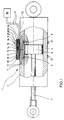
- the housing wall 4 of the high pressure cylinder 1 consists of magnetically conductive and consequently shielding steel with a wall thickness of approximately 10 mm.
- the piston 3 has two opposite end faces, on which two permanent magnets 5 and 6 are arranged opposite one another.
- the two permanent magnets 5 and 6 are arranged adjacent to the housing wall 4, the north pole-south pole axis of both permanent magnets 5 and 6 pointing in the same direction.
- a main magnetic flux forms in the upper part of the housing wall, as can be seen from the field lines 7.
- a magnetic shunt bridge 8 is arranged, which consists essentially of two magnetic conductors 9 and 10.
- the two magnetic conductors 9 and 10 are aligned parallel to the cylinder axis and each have a first end 11 or 12 on the outside of the housing wall 4.
- the respective second ends 13 and 14 of the two magnetic conductors 9 and 10 face each other and overlap to form an air gap 15.
- a Hall probe 16 is arranged in the air gap 15 and is connected to an evaluation unit 18 via lines 17.
- the magnetic conductors 9 and 10 and the Hall probe 16 are cast together in a protective housing 19 made of an insulating plastic.
- the distance between the first ends 11 and 12 of the two magnetic conductors 9 and 10, as can be seen in FIG. 1, is smaller than the length of the main magnetic flux which forms in the housing wall 4.
- tensioning straps 21 which each surround the protective housing 19 and the housing wall 4 of the high-pressure cylinder 1.
- the tensioning straps 21 are commercially available hose clamps.
- the magnetic conductors 9 and 10 are parallel to the main flow forming in the housing wall 4, so that the magnetic conductors 9, preferably from a dynamo sheet or a magnetically soft sheet with grain-oriented Preferred direction exist, derived part of the magnetic flux, so that a magnetic secondary flow is branched off via the bridge 8.
- a magnetic field is generated in the air gap 15 between the two overlapping second ends 13 and 14.
- the Hall probe located in the air gap 15 detects this magnetic field and sends a corresponding signal to the evaluation unit 18 via the line 17.
- a switching relay can also be provided, which acts on a hydraulic valve for supplying the high-pressure hydraulic cylinder 1. In this way, the hydraulic high-pressure cylinder can be switched off using the bridge 8.
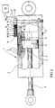
- FIG. 3 shows a variant of the high-pressure cylinder from FIGS. 1 and 2. For the sake of clarity, the bridge is not shown.
- This variant differs from the high-pressure cylinder from FIG. 1 only by the device for generating a main magnetic flux in the housing wall 4 of the high-pressure cylinder 1.
- a single permanent magnet 22 is necessary on the end face of the piston 3 facing away from the piston rod 2.
- a cross-sectionally T-shaped rotary body 23 made of a magnetically conductive material, the outline of which is adapted to the outline of the piston 3.
- This rotary body 23, together with the piston 3, causes the field lines 7 to form as shown in FIG. 3, so that a relatively long main magnetic flux is obtained in the housing wall 4.
- FIGS. 3 and 4 show a further variant.
- This variant differs from the variant according to FIG. 3 only in that a plurality of permanent magnets 24 are fastened uniformly distributed over the circumference of the piston on the end face of the piston 3 facing away from the piston rod 2.
- Both variants according to FIGS. 3 and 4 have in common that the main magnetic flux in the housing wall 4 is formed symmetrically to the cylinder axis. It is therefore irrelevant at which point on the circumference of the housing wall 4 of the high-pressure cylinder 1 the bridge 8 is fastened in order to branch off the magnetic secondary flow for generating a switch-off or control signal. Otherwise, the functioning of the variants according to FIGS. 3 and 4 corresponds to the functioning of the high-pressure piston 1 according to FIGS. 1 and 2.
Landscapes
- Physics & Mathematics (AREA)
- Engineering & Computer Science (AREA)
- General Physics & Mathematics (AREA)
- Fluid Mechanics (AREA)
- Mechanical Engineering (AREA)
- General Engineering & Computer Science (AREA)
- Actuator (AREA)
- Measurement Of Length, Angles, Or The Like Using Electric Or Magnetic Means (AREA)
- Transmission And Conversion Of Sensor Element Output (AREA)
Abstract
Description
- Die Erfindung bezieht sich auf einen Stellantrieb mit einem hinter einer Gehäusewand bewegbaren Stellglied, an dem eine Einrichtung zum Erzeugen eines magnetischen Feldes angebracht ist, und einem vor der Gehäusewand anbringbaren Magnetfeldsensor.
- Aus der Praxis sind pneumatische Stellantriebe der eingangs genannten Art, sogenannte Pneumatikzylinder, bekannt. Diese Pneumatikzylinder weisen einen im Innern einer Zylinderwandung hin- und herbeweglichen Kolben auf, der mit einer aus der Stirnseite des Zylinders heraustretenden Kolbenstange verbunden ist. Die Zylinderwandung besteht bei den bekannten Pneumatikzylindern in der Regel aus Nichteisen-Metallen, z. B. Bronze, Aluminium oder dergleichen. An dem Kolben der Pneumatikzylinder ist ein Dauermagnet vorgesehen, dessen Nordpol-Südpol-Achse im wesentlichen senkrecht zur Zylinderwandung zeigt. Die von dem Dauermagneten erzeugten Feldlinien können im wesentlichen ungehindert durch die Zylinderwandung austreten. Auf der Außenseite der Zylinderwand ist eine Hallsonde vorgesehen, die von dem Magnetfeld des Dauermagnten beeinflußt wird, wenn sich der Kolben in einer vorbestimmten Stellung befindet. Auf diese Weise ist es möglich, die Kolbenstellung des Pneumatikzylinders zu erfassen, um somit die Bewegung des Pneumatikzylinders zu steuern bzw. den Pneumatikzylinder bei einer vorbestimmten Kolbenstellung abzuschalten.
- Nun werden in der Praxis auch sogenannte hydraulische Hochdruckzylinder verwendet. Ihr Einsatzbereich reicht von Hebebühnen zu Schienenlegefahrzeugen, usw. Häufig ist der Einbauort solcher hydraulischer Hochdruckzylinder sehr beengt. Gleichwohl besteht das Bedürfnis, auch bei hydraulischen Hochdruckzylindern die Kolbenstellung erfassen zu können. Anders als bei dem pneumatischen Stellzylinder besteht die Zylinderwand bei hydraulischen Hochdruckzylindern jedoch zumeist aus Stahl. Stahl ist ein magnetisch leitender Werkstoff und würde daher das Magnetfeld eines am Kolben angeordneten Dauermagneten nach außen abschirmen. Hinzu kommt, daß die Wandstärken der hydraulischen Hochdruckzylinder aufgrund der enormen Arbeitsdrücke verhältnismäßig groß sind, so daß auf der Außenseite der Zylinderwandung kein für eine zuverlässige Steuerung ausreichendes magnetisches Feld mehr zu orten ist. Es hat daher bereits Versuche gegeben, mit anderen weit aufwendigeren Methoden die Kolbenstellung bei Hydraulikhochdruckzylindern zu erkennen. All diesen Methoden ist gemein, daß sie verhältnismäßig teuer sind und daß sie auf der Außenseite der Zylinderwandung einen größeren Bauraum beanspruchen als häufig zur Verfügung steht. Ein ähnlicher Stellantrieb ist auch aus der DE-A-3015 258 bekannt.
- Es ist daher Aufgabe der vorliegenden Erfindung, einen Stellantrieb der eingangs genannten Art so zu verbessern, daß auch bei einer magnetisch abschirmenden Gehäusewand die Stellung des Stellgliedes auf einfache Weise und ohne großen baulichen Aufwand erfaßt werden kann.
- Diese Aufgabe wird erfindungsgemäß dadurch gelöst, daß die Gehäusewand aus einem magnetisch leitenden Material hergestellt ist, in welchem Feldlinien des magnetischen Feldes in der Gehäusewand einen zur Vorderseite der Gehäusewand abgeschirmten Hauptfluß bilden, und daß zur Erzeugung eines magnetischen Nebenflusses an der Vorderseite der Gehäusewand wenigstens ein, zwei Enden aufweisender magnetischer Leiter angeordnet ist, dessen erstes Ende der Gehäusewand benachbart ist, und dessen zweites Ende einen Luftspalt begrenzt, in den der Magnetfeldsensor angebracht ist.
- In einer besonders bevorzugten Ausgestaltung der Erfindung sind zwei magnetische Leiter vorgesehen, deren zweite Enden unter Bildung des Luftspaltes einander gegenüberliegend angeordnet sind.
- Diese Lösung ermöglicht auch bei Stellantrieben mit magnetisch abschirmender Gehäusewand auf einfache Weise die Erfassung der Stellung des Stellgliedes. Das hinter der Gehäusewand erzeugte Magnetfeld wird durch das magnetisch abschirmende Material, das stets zugleich auch ein magnetisch leitendes Material ist, abgelenkt, so daß sich in der Gehäusewand zwangsläufig der magnetische Hauptfluß ausbildet, ohne daß die Feldlinien zur Vorderseite der Gehäusewand austreten würden. Dadurch, daß die magnetischen Leiter jeweils mit einem Ende der Gehäusewand benachbart sind, teilt sich der in der Gehäusewand ausgebildete Hauptfluß unter Spaltung eines in die magnetischen Leiter abwandernden Nebenflusses auf, so daß auch in dem Luftspalt zwischen den beiden zweiten Enden der magnetischen Leiter ein Magnetfeld erzeugt wird. Ein in diesem Luftspalt angeordneter Magnetfeldsensor erfaßt die Änderungen des dort erzeugten Magnetfeldes jeweils in Abhängigkeit der Stellung des Stellgliedes. Ein besonderer Vorteil des erfindungsgemäßen Stellantriebes liegt darin, daß der Platzbedarf für die beiden magnetischen Leiter äußerst gering ist, so daß der Einsatzzweck solcher Stellantriebe nahezu unbegrenzt ist.
- Die Vorteile der Erfindung kommen in besonderem Maße zum Tragen, wenn der Stellantrieb als hydraulischer Hochdruckzylinder mit einen mit einer Kolbenstange verbundenen Kolben als Stellglied ausgebildet ist, wobei die Zylinderwand die Gehäusewand bildet. Denn gerade bei solchen hydraulischen Hochdruckzylindern ermöglicht die erfindungsgemäße Lösung das ansonsten recht aufwendige Erfassen der Kolbenstellung auf besonders einfache Weise, wobei sich die Erfindung hier gerade zu Nutzen macht, daß die Zylinderwand aus einem magnetisch abschirmenden Material besteht.
- Obwohl die Erzeugung des magnetischen Feldes auch durch eine Spule möglich wäre, wird bevorzugt, wenn die Einrichtung zum Erzeugen eines magnetischen Feldes als Magnet, insbesondere Dauermagnet, ausgebildet ist. Die Ausbildung als Dauermagnet hat den Vorteil, daß keine elektrischen Verbindungen ins Innere des Stellantriebes geführt werden müssen.
- Die beiden magnetischen Leiter lassen sich besonders flach an der Gehäusewand des Stellantriebes anbringen, wenn sich die zweiten Enden der magnetischen Leiter unter Bildung des Luftspaltes überlappen, so daß die magnetischen Leiter und der Magnetfeldsensor eine Brücke bilden. Diese Brücke kann durch die sich überlappenden Enden der magnetischen Leiter sehr flach sein. Die Höhe der Brücke wird durch die Dicke der magnetischen Leiter und des Magnetfeldsensors, der üblicherweise eine Hallsonde ist, bestimmt.
- Um bei voneinander verschiedenen Stellungen des Kolbens bzw. des Stellgliedes einen Schaltvorgang auslösen zu können, ist es vorteilhaft, wenn die Brücke in einem Schutzgehäuse angeordnet ist, welches mit einer Halterung an einer vorbestimten Stelle auf dem Hochdruckzylinder anbringbar ist. Das Schutzgehäuse dient dabei als Schutz der Brücke vor äußeren Einflüssen.
- Besonders günstig ist es, wenn die Brücke in ein das Schutzgehäuse bildendes, isolierendes Material eingegossen ist. Die magetischen Leiter brauchen dann nicht auf besondere Weise in dem Schutzgehäuse gehalten werden, sie werden vielmehr durch das isolierende Material selbst umschlossen.
- Der durch die magnetischen Leiter abgezweigte Nebenfluß läßt sich auf einfache Weise dadurch verstärken, daß die magnetischen Leiter aus Dynamoblech hergestellt sind. Dieses Dynamoblech weist gegenüber normalem Blech bereits eine erhöhte Permeabilität auf.
- In diesem Zusammmenhang wird besonders bevorzugt, wenn die magnetischen Leiter aus Blech mit kornorientierter Vorzugsrichtung hergestellt sind, da dieses Blech sich durch Permeabilität auszeichnet, die noch höher ist als die von Dynamoblechen.
- Obwohl ein magnetischer Nebenfluß in den magnetischen Leitern bereits zustandekommen könnte, wenn die ersten Enden in geringem Abstand zur Vorderseite der Gehäusewand liegen, wird der magnetische Nebenfluß wesentlich stärker, wenn die beiden ersten Enden im magnetischen Leiter die Gehäusewand berühren.
- Zur Verstärkung des sich in den magnetischen Leitern ausbildenden Nebenflusses trägt in günstiger Weise auch bei, wenn der Abstand zwischen den ersten Enden der beiden Magnetischen Leitern kleiner oder gleich der Länge des magnetischen Hauptflusses in der magnetisch abschirmenden Gehäusewand ist. Die Länge des magnetischen Hauptflusses in der magnetisch abschirmenden Gehäusewand wird im wesentlichen durch die Anordnung der an dem Stellglied vorgesehenen Magnete bestimmt. Diese Länge bleibt daher für den jeweils zu betrachtenden Stellzylinder unabhängig von der Stellung des Stellgliedes gleich. Durch Verschieben des Stellgliedes verlagert sich lediglich der Ort, nicht aber die Länge des in der Gehäusewand ausgebildeten magnetischen Hauptflusses.
- Die Brücke mit dem Magnetfeldsensor läßt sich besonders einfach an der Außenseite des Stellantriebes bzw. des Stellzylinders anbringen, wenn die Halterung des Schutzgehäuses aus mindestens einem das Schutzgehäuse und die Zylinderwand umgreifenden Spannband besteht. Wenn das Spannband gelöst wird, kann das die Brücke beinhaltende Schutzgehäuse an eine andere Stelle des Stellantriebes geschoben werden, so daß eine andere Kolbenstellung erfaßt werden kann.
- Eine besonders einfache Art der Befestigung des Schutzgehäuses an der Zylinderwand ergibt sich, wenn das Spannband in Form einer Schlauchklemme ausgebildet ist. Solche Schlauchklemmen sich handelsüblich und lassen sich leicht mit einem Schraubendreher lösen und festspannen.
- Für die Erzeugung des magnetischen Hauptflusses in der Gehäusewand ist es günstig, wenn der Kolben aus einem magnetisch leitenden Material ausgebildet ist und wenn mindestens ein Dauermagnet an einer der beiden Stirnflächen des Kolbens angeordnet ist. Das hat den Vorteil, daß die Länge des Kolbens die Länge der magnetischen Feldlinien mitbestimmt.
- Wenn dabei vorzgsweise die Nordpol-Südpol-Achse des Dauermagneten im wesentlichen parallel zur Gehäusewand angeordnet ist, bedeutet das, daß die Länge des magnetischen Hauptflusses in der Gehäusewand durch die Länge des Dauermagneten und die Länge des Kolbens bestimmt wird. So ist es auf einfache Weise möglich, in der Gehäusewand einen magnetischen Hauptfluß vorzusehen, dessen Länge stets größer ist als der Abstand der beiden ersten Enden der magnetischen Leiter der Brücke.
- Im diesem Zusammenhang ist es auch günstig, wenn mindestens ein Dauermagnet auf jeder der beiden Stirnflächen des Kolbens so angeordnet ist, daß sich jeweils zwei Dauermagnete gegenüberliegen, deren Nordpol-Südpol-Achse in die gleiche Richtung zeigt. Hierdurch wird die Länge des sich in der Gehäusewand ausbildenden magnetischen Hauptflusses noch weiter vergrößert.
- Eine baulich besonders einfache Anordnung der Dauermagnete ergibt sich, wenn die Nordpol-Südpol-Achsen der Dauermagnete zur Gehäusewand benachbart sind. Es kann dann zwar sein, daß sich nicht über den gesamten Umfang der Zylinderwand ein ausreichender magnetischer Fluß ausbildet, dafür reicht jedoch das Vorsehen eines einzigen, relativ schwachen Dauermagneten.
- Gemäß einer anderen Ausführungsform kann an einer Stirnfläche des Kolbens unter Bildung eines Zwischenraumes ein magnetisch leitender, dem Umfang des Kolbens angepaßter Körper befestigt sein, wobei in dem Zwischenraum mindestens ein Dauermagnet angeordnet ist. Auf diese Weise wird in der Gehäusewand ein in Richtung der Zylinderachse gerichteter magnetischer Hauptfluß erzeugt, der symmetrisch zur Zylinderachse verteilt ist. Für die Anordnung der den Magnetfeldsensor enthaltenen Brücke ist daher die Lage bezüglich des Umfanges der Zylinderwand egal.
- Anstelle eines einzigen Magneten können auch auf einer Seite des Kolbens mehrere Magnete über den Umfang des Kolbens verteilt angeordnet sein. Auch hierdurch läßt sich ein im wesentlichen symmetrisch zur Zylinderachse ausgebildeter magnetischer Hauptfluß in der Gehäusewand erreichen.
- Im folgenden werden Ausführungsbeispiele der Erfindung anhand einer Zeichnung näher erläutert. Es zeigen:
- Fig. 1
- eine Seitenansicht durch einen teilweise geschnittenen, schematisch dargestellten Hydraulikhochdruckzylinder mit einer am Außenumfang angeordneten Nebenschlußbrücke,
- Fig.2
- den hydraulischen Hochdruckzylinder aus Fig. 1, jedoch mit verschoben angebrachter Nebenschlußbrücke,
- Fig. 3
- einen Längsschnitt durch einen Teil eines Hochdruckzylinders gemäß einer ersten Variante und
- Fig. 4
- einen Schnitt durch einen Teil eines Hydraulikhochdruckzylinders gemäß einer zweiten Variante.
- In Fig. 1 ist ein als hydraulischer Hochdruckzylinder 1 ausgebildeter Stellantrieb dargestellt, dessen mit einer Kolbenstange 2 verbundener Kolben 3 als Stellglied im Inneren des Hochdruckzylinders 1 hin- und herbeweglich gelagert ist. Die Hydraulikanschlüsse des Hochdruckzylinders 1 sind der Übersichtlichkeit halber nich dargestellt. Die Gehäusewand 4 des Hochdruckzylinders 1 besteht aus magnetisch leitendem und folglich abschirmendem Stahl mit einer Wandstärke von etwa 10 mm.
- Der Kolben 3 weist zwei gegenüberliegende Stirnflächen auf, auf denen zwei Dauermagnete 5 und 6 einander gegenüberliegende angeordnet sind. Bei diesem, in den Figuren 1 und 2 gezeigten Ausführungsbeispiel, sind die beiden Dauermagnete 5 und 6 der Gehäusewand 4 benachbart angeordnet, wobei die Nordpol-Südpol-Achse beider Dauermagneten 5 und 6 in die gleiche Richtung weist.
- Wie aus Fig. 1 ersichtlich ist, bildet sich in dem oberen Teil der Gehäusewand ein magnetischer Hauptfluß aus, wie anhand der Feldlinien 7 erkennbar ist.
- Auf der Außenseite der Gehäusewand 4 ist eine magnetische Nebenschlußbrücke 8 angeordnet, die im wesentlichen aus zwei magnetischen Leitern 9 und 10 beseht. Die beiden magnetischen Leiter 9 und 10 sind parallel zur Zylindersachse ausgerichtet und liegen jeweils mit einem ersten Ende 11 bzw. 12 an der Außenseite der Gehäusewand 4 an. Die jeweiligen zweiten Enden 13 und 14 der beiden magnetischen Leiter 9 und 10 sind aufeinander zugerichtet und überlappen einander unter Bildung eines Luftspaltes 15. In dem Luftspalt 15 ist eine Hallsonde 16 angeordnet, die über Leitungen 17 mit einer Auswerteeinheit 18 verbunden ist. Die magnetischen Leiter 9 und 10 sowie die Hallsonde 16 sind gemeinsam in ein Schutzgehäuse 19 aus einem isolierenden Kunststoff eingegossen. Der Abstand der ersten Enden 11 und 12 der beiden magnetischen Leiter 9 und 10 zueinander ist, wie aus Fig. 1 ersichtlich ist, kleiner als die Länge des sich in der Gehäusewand 4 ausbildenden magnetischen Hauptflusses.
- Auf der Oberseite des Schutzgehäuses 19 sind Vertiefungen 20 eingearbeitet, in den Spannbänder 21 liegen, die jeweils das Schutzgehäuse 19 und die Gehäusewand 4 des Hochdruckzylinders 1 umgeben. Wie besser aus Fig. 2 ersichtlich ist, handelt es sich bei den Spannbändern 21 um handelsübliche Schlauchklemmen.
- Im folgenden wird die Wirkungsweise des in den Figuren 1 und 2 gezeigten Stellantriebes näher erläutert.
- Wenn sich der Kolben 3 in einer vorbestimmten Stellung bezüglich der Brücke 8 befindet (vgl. Fig. 1), so daß die magnetischen Leiter 9 und 10 parallel zu den sich in der Gehäusewand 4 ausbildenden Hauptfluß liegen, wird durch die magnetischen Leiter 9, die vorzugsweise aus einem Dynamoblech bzw. einem magnetisch weichen Blech mit kornorientierter Vorzugsrichtung bestehen, ein Teil des magnetischen Flusses abgeleitet, so daß über die Brücke 8 ein magnetischer Nebenfluß abgezweigt wird. Hierdurch wird in dem Luftspalt 15 zwischen den beiden sich überlappenden zweiten Enden 13 und 14 ein magnetisches Feld erzeugt. Die in dem Luftspalt 15 befindliche Hallsonde erfaßt dieses magnetische Feld und gibt ein entsprechendes Signal über die Leitung 17 an die Auswerteeinheit 18.
- Wenn der Kolben 3 entlang der Zylinderachse weiterverschoben wird, ändert sich die Stärke des magnetischen Feldes in dem Luftspalt 15, was ebenfalls von der Hallsonde 16 registriert wird. Gleiches passsiert, wenn die in dem Schutzgehäuse 19 befindliche Brücke 8 entlang der Gehäusewand 4 verschoben wird. Dies läßt sich einfach dadurch bewerkstelligen, daß die Spannbänder 21 gelockert werden, wonach das Schutzgehäuse 19 in Richtung der Zylinderachse verschoben werden kann, z. B. in die in Fig. 2 gezeigte Stellung. Wenn der Kolben nicht verschoben wird, befindet sich die Brücke 8 nun in einer Stellung, in der kein nennenswerter magnetischer Nebenfluß abgezweigt werden kann. Eine der in Fig. 1 dargstellt vergleichbare Situation entsteht erst, wenn der Kolben 3 in die strichliert gezeigte Stellung nach rechts verschoben wird.
- Anstatt einer Auswerteeinheit 18 kann auch ein Schaltrelais vorgesehen sein, das auf ein Hydraulikventil zur Versorgung des Hydraulikhochdruckzylinders 1 wirkt. Auf diese Weise kann mit Hilfe der Brücke 8 ein Abschalten des hydraulischen Hochdruckzylinders bewirkt werden.
- In Fig. 3 ist eine Variante des Hochdruckzylinders aus den Figuren 1 und 2 dargestellt. Der übersichtlichkeit halber ist die Brücke nicht mit dargestellt. Diese Variante unterscheidet sich von dem Hochdruckzylinder aus Fig. 1 lediglich durch die Einrichtung zur Erzeugung eines magnetischen Hauptflusses in der Gehäusewand 4 des Hochdruckzylinders 1. So ist bei der in Fig. 3 beschriebenen Variante ein einziger Dauermagnet 22 nötig auf der der Kolbenstange 2 abgewandten Stirnseite des Kolbens 3. Auf der dem Kolben 3 abgewandten Stirnseite des Dauermagneten 22 ist ein im Querschnitt T-förmiger Rotationskörper 23 aus einem magnetisch leitenden Material befestigt, dessen Grundriß dem Grundriß des Kolbens 3 angepaßt ist. Dieser Rotationskörper 23 bewirkt zusammen mit dem Kolben 3, daß sich die Feldlinien 7 so ausbilden, wie in Fig. 3 gezeigt ist, so daß in der Gehäusewand 4 ein relativ langer magnetischer Hauptfluß erhalten wird.
- In Fig. 4 ist eine weitere Variante dargestellt. Diese Variante unterscheidet sich von der Variante gemäß Fig. 3 ledliglich dadurch, daß auf der der Kolbenstange 2 abgewandten Stirnfläche des Kolbens 3 mehrere Dauermagneten 24 gleichmäßig über den Umfang des Kolbens verteilt befestigt sind. Beiden Varianten gemäß Fig. 3 und 4 ist gemein, daß sich der magnetische Hauptfluß in der Gehäusewand 4 symmetrisch zur Zylinderachse ausbildet. Es spielt daher keine Rolle, an welcher Stelle des Umfanges der Gehäusewand 4 des Hochdruckzylinders 1 die Brücke 8 befestigt wird, um den magnetischen Nebenfluß zur Erzeugung eines Abschalt- oder Steuersignales abzuzweigen. Ansonsten enspricht die Funktionsweise der Varianten gemäß Fig. 3 und 4 der Funktionsweise des Hochdruckkolbens 1 gemäß Fig. 1 und 2.
- Zwar ist es auch denkbar, die Hallsonde unmittelbar auf der Außenseite der Zylinderwand anzuordnen und nur einen magnetischen Leiter vorzusehen, dessen zweites Ende die Rückseite der Hallsonde abdeckt; dann wird der zu erwartende magnetische Nebenfluß jedoch geringer sein, da aufgrund des Luftspalts zur Zylinderwand der magnetische Widerstand erhöht ist.
Claims (21)
- Stellantrieb mit einem hinter einer Gehäusewand (4) bewegbaren Stellglied (3), an dem eine Einrichtung (5, 6); 22; 24) zum Erzeugen eines magnetischen Feldes angebracht ist, und einem vor der Gehäusewand (4) anbringbaren Magnetfeldsensor (16), dadurch gekennzeichnet, daß die Gehäusewand (4) aus einem magnetisch leitenden Material hergestellt ist, in welchem Feldlinien (7) des magnetischen Feldes in der Gehäusewand (4) einen zur Vorderseite der Gehäusewand (4) abgeschirmten Hauptfluß bilden, und daß zur Erzeugung eines magnetischen Nebenflusses an der Vorderseite der Gehäusewand (4) wenigstens ein, zwei Enden (11, 13; 12, 14) aufweisender magnetischer Leiter (9, 10) angeordnet ist, dessen erstes Ende (11, 12) der Gehäusewand (4) benachbart ist, und dessen zweites Ende (13, 14) einen Luftspalt (15) begrenzt, in dem der Magnetfeldsensor (16) angebracht ist.
- Stellantrieb nach Anspruch 1, dadurch gekennzeichnet, daß zwei magnetische Leiter (9, 10) vorgesehen sind, deren zweite Enden (13, 14) unter Bildung des Luftspaltes (15) einander gegenüberliegend angeordnet sind.
- Stellantrieb nach Anspruch 1 oder 2, dadurch gekennzeichnet, daß der Stellantrieb als hydraulischer Hochdruckzylinder (1) mit einem mit einer Kolbenstange (2) verbundenen Kolben (3) als Stellglied ausgebildet ist, wobei die Zylinderwand die Gehäusewand (4) bildet.
- Stellantrieb nach einem der Ansprüche 1 bis 3, dadurch gekennzeichnet, daß die Einrichtung zur Erzeugung eines magnetischen Feldes als Magnet (5, 6; 22; 24) ausgebildet ist.
- Stellantrieb nach Anspruch 4, dadurch gekennzeichnet, daß der Magnet (5, 6; 22; 24) als Dauermagnet ausgebildet ist.
- Stellantrieb nach einem der Ansprüche 2 bis 5, dadurch gekennzeichnet, daß sich die zweiten Enden (13, 14) der magnetischen Leiter (9, 10) unter Bildung des Luftspaltes (15) gegenseitig überlappen, so daß die magnetischen Leiter (9, 10) und der Magnetfeldsensor (16) eine Brücke (8) bilden.
- Stellantrieb nach Anspruch 6, dadurch gekennzeichnet, daß die Brücke (8) in einem Schutzgehäuse (19) angeordnet ist, welches mit einer Halterung an einer vorbestimmten Stelle an der Gehäusewand (4) des Hochdruckzylinders (1) anbringbar ist.
- Stellantrieb nach Anspruch 6 oder 7, dadurch gekennzeichnet, daß die Brücke (8) in ein das Schutzgehäuse (19) bildendes isolierendes Material eingegossen ist.
- Stellantrieb nacch einem der Ansprüche 1 bis 8, dadurch gekennzeichnet, daß der oder die magnetischen Leiter (9, 10) aus Dynamoblech hergestellt sind.
- Stellantrieb nach einem der Ansprüche 1 bis 9, dadurch gekennzeichnet, daß der oder die magnetischen Leiter (9, 10) aus Blech mit kornorientierter Vorzugsrichtung hergestellt sind.
- Stellantrieb nach einem der Ansprüche 1 bis 10, dadurch gekennzeichnet, daß die ersten Enden (11, 12) der magnetischen Leiter (9, 10) die Gehäusewand (4) berühren.
- Stellantrieb nach einem der Ansprüche 2 bis 11, dadurch gekennzeichnet, daß der Abstand zwischen den ersten Enden (11, 12) der beiden magnetischen Leiter (9, 10) kleiner oder gleich der Länge des magnetischen Hauptflusses in der magnetisch abschirmenden Gehäusewand (4) ist.
- Stellantrieb nach einem der Ansprüche 7 bis 12, dadurch gekennzeichnet, daß die Halterung des Schutzgehäuses (19) aus mindestens einem, das Schutzgehäuse (19) und die Gehäusewand (4) umgreifenden Spannband (21) besteht.
- Stellantrieb nach Anspruch 13, dadurch gekennzeichnet, daß das Spannband (21) in Form einer Schlauchklemme ausgebildet ist.
- Stellantrieb nach einem der Ansprüche 3 bis 14, dadurch gekennzeichnet, daß der Kolben (3) aus einem magnetisch leitenden Material ausgebildet ist, und daß mindestens ein Dauermagnet (5, 6; 22; 24) an einer der beiden Stirnflächen des Kolbens (3) angeordnet ist.
- Stellantrieb nach einem der Ansprüche 5 bis 15, dadurch gekennzeichnet, daß die Nordpol-Südpol-Achse des Dauermagneten (5, 6; 22; 24) im wesentlichen parallel zur Gehäusewand (4) angeordnet ist.
- Stellantrieb nach einem der Ansprüche 3 bis 16, dadurch gekennzeichnet, daß mindestens ein Dauermagnet (5, 6) auf jeder der beiden Stirnflächen des Kolbens (3) so angeordnet ist, daß sich jeweils zwei Dauermagnete (5, 6) gegenüberliegen.
- Stellantrieb nach Anspruch 17, dadurch gekennzeichnet, daß die Nordpol-Südpol-Achse der beiden sich gegenüberliegenden Dauermagneten (5, 6) in die gleiche Richtung zeigt.
- Stellantrieb nach Anspruch 17 oder 18, dadurch gekennzeichnet, daß die Nordpol-Südpol-Achsen der Dauermagnete (5, 6) zur Gehäusewand (4) benachbart sind.
- Stellantrieb nach einem der Ansprüche 3 bis 19, dadurch gekennzeichnet, daß an einer Stirnfläche des Kolbens (3) unter Bildung eines Zwischenraumes ein magnetisch leitender, dem Umfang des Kolbens (3) angepaßter Körper (23) befestigt ist, wobei in dem Zwischenraum mindestens ein Dauermagnet (22; 24) angeordnet ist.
- Stellantrieb nach einem der Ansprüche 3 bis 20, dadurch gekennzeichnet, daß auf einer Stirnfläche des Kolbens (3) mehrere Magneten (24) über den Umfang des Kolbens (3) verteilt angeordnet sind.
Priority Applications (1)
| Application Number | Priority Date | Filing Date | Title |
|---|---|---|---|
| AT89913080T ATE88009T1 (de) | 1989-02-15 | 1989-10-19 | Stellantrieb. |
Applications Claiming Priority (2)
| Application Number | Priority Date | Filing Date | Title |
|---|---|---|---|
| DE8901770U DE8901770U1 (de) | 1989-02-15 | 1989-02-15 | Stellantrieb |
| DE8901770U | 1989-02-15 |
Publications (2)
| Publication Number | Publication Date |
|---|---|
| EP0457762A1 EP0457762A1 (de) | 1991-11-27 |
| EP0457762B1 true EP0457762B1 (de) | 1993-04-07 |
Family
ID=6836062
Family Applications (1)
| Application Number | Title | Priority Date | Filing Date |
|---|---|---|---|
| EP89913080A Expired - Lifetime EP0457762B1 (de) | 1989-02-15 | 1989-10-19 | Stellantrieb |
Country Status (5)
| Country | Link |
|---|---|
| US (1) | US5231352A (de) |
| EP (1) | EP0457762B1 (de) |
| JP (1) | JPH0776682B2 (de) |
| DE (2) | DE8901770U1 (de) |
| WO (1) | WO1990009563A1 (de) |
Cited By (5)
| Publication number | Priority date | Publication date | Assignee | Title |
|---|---|---|---|---|
| WO1998040699A1 (de) * | 1997-03-12 | 1998-09-17 | Pepperl + Fuchs Gmbh | Vorrichtung zur positionserfassung eines beweglich angeordneten magneten zum erzeugen eines magnetischen feldes |
| DE19711781A1 (de) * | 1997-03-12 | 1998-10-01 | Pepperl & Fuchs | Vorrichtung zur Positionserfassung eines beweglich angeordneten Magneten zum Erzeugen eines magnetischen Feldes durch eine Wandung aus ferromagnetischem Material hindurch, insbesondere Stellantrieb mit bewegbarem Stellglied |
| DE19805225A1 (de) * | 1998-02-10 | 1999-08-12 | Festo Ag & Co | Positionserfassungsvorrichtung |
| DE102005030722A1 (de) * | 2005-07-01 | 2007-01-04 | Bosch Rexroth Teknik Ab | Druckmittelzylinder |
| DE102011121870A1 (de) * | 2011-12-21 | 2013-06-27 | Conti Temic Microelectronic Gmbh | Magnetsensoranordnung |
Families Citing this family (62)
| Publication number | Priority date | Publication date | Assignee | Title |
|---|---|---|---|---|
| US5243941A (en) * | 1991-07-29 | 1993-09-14 | Asmo Co., Ltd. | Actuator for engine idling control mechanism |
| FR2691534B1 (fr) * | 1992-05-19 | 1994-08-26 | Moving Magnet Tech | Capteur de position à aimant permanent et sonde de hall. |
| US5583211A (en) * | 1992-10-29 | 1996-12-10 | Beckman Instruments, Inc. | Surface activated organic polymers useful for location - specific attachment of nucleic acids, peptides, proteins and oligosaccharides |
| EP0595553B1 (de) * | 1992-10-29 | 1996-12-27 | Rolls-Royce And Associates Limited | Verbesserung in Weggebern |
| US5365791A (en) * | 1992-11-10 | 1994-11-22 | Allied-Signal Inc. | Signal generator |
| DE4429857C2 (de) * | 1994-08-23 | 2000-06-29 | Balluff Gebhard Feinmech | Detektor für Magnetposition |
| DE19504229A1 (de) * | 1995-02-09 | 1996-08-14 | Festo Kg | Positions-Sensoreinrichtung |
| US6346806B1 (en) | 1997-03-12 | 2002-02-12 | Pepperl +Fuchs Gmbh | Device for detecting the position of a moveable magnet to produce a magnetic field |
| DE19712829B4 (de) * | 1997-03-26 | 2005-02-17 | Sick Ag | Vorrichtung zur Erkennung der Position eines beweglichen Gegenstandes |
| DE19738316A1 (de) * | 1997-09-02 | 1999-03-04 | Itt Mfg Enterprises Inc | Berührungsloser Wegmesser insbesondere zur Verschleißmessung von Bremsklötzen |
| US6099235A (en) * | 1997-12-04 | 2000-08-08 | Spectra Precision, Inc. | Arrangement for determining the relative angular orientation between a first machine element and a second machine element |
| US6447240B1 (en) | 1997-12-04 | 2002-09-10 | Trimble Navigation Limited | Arrangement for determining the relative angular orientation between a first machine element and a second machine element |
| US6325590B1 (en) | 1997-12-04 | 2001-12-04 | Spectra Precision, Inc. | Arrangement for determining the relative angular orientation between a first machine element and a second machine element |
| US6119579A (en) * | 1998-03-20 | 2000-09-19 | Caterpillar Inc. | Apparatus and method for detecting piston location within a fluid cylinder of a work machine |
| US6095248A (en) * | 1998-11-03 | 2000-08-01 | Halliburton Energy Services, Inc. | Method and apparatus for remote control of a tubing exit sleeve |
| DE19956313A1 (de) * | 1999-11-12 | 2001-05-23 | Atecs Mannesmann Ag | Magnetfeldsensor zur Ermittlung der Position eines beweglichen Objekts |
| US6411081B1 (en) * | 2000-02-10 | 2002-06-25 | Siemens Ag | Linear position sensor using magnetic fields |
| US6510719B2 (en) * | 2000-04-28 | 2003-01-28 | Novartec @ Ag | Pressing tool and pressing process for extruding press fittings |
| FR2809487B1 (fr) * | 2000-05-23 | 2002-08-16 | Sagem | Capteur de position axiale pour une tige mobile axialement et actionneur electromagnetique de soupape qui en est equipe |
| US6670805B1 (en) * | 2000-09-22 | 2003-12-30 | Alliant Techsystems Inc. | Displacement sensor containing magnetic field sensing element between a pair of biased magnets movable as a unit |
| DE10240976B4 (de) * | 2001-09-03 | 2005-07-07 | Smc K.K. | Sensorbefestigung für Stellgliedkörper |
| US6907795B2 (en) * | 2001-11-09 | 2005-06-21 | Stoneridge Control Devices, Inc. | Seat position sensor |
| DE10161541B4 (de) * | 2001-12-11 | 2005-05-04 | Balluff Gmbh | Sensoranordnung und Funktionseinheit mit Sensoranordnung |
| US7186094B2 (en) * | 2003-03-26 | 2007-03-06 | Gas Machinery Research Council | Method and apparatus for measuring work performed by a compressor |
| WO2004099724A2 (en) | 2003-05-06 | 2004-11-18 | Sri International | Hydraulic cylinder with piston and a magnetic layer on the piston rod for piston position determination |
| WO2005050714A2 (en) * | 2003-11-18 | 2005-06-02 | Halliburton Energy Services, Inc. | High temperature electronic devices |
| CA2471982A1 (en) * | 2004-04-20 | 2005-10-20 | Eldesco Corporation | Piston velocity detector |
| US7999538B2 (en) * | 2004-06-15 | 2011-08-16 | Asa Electronic Industry Co., Ltd. | Device and system for detecting position |
| JP4558531B2 (ja) * | 2005-02-14 | 2010-10-06 | 株式会社小松製作所 | シリンダの位置計測装置 |
| JP4628815B2 (ja) * | 2005-02-18 | 2011-02-09 | 株式会社小松製作所 | シリンダの位置計測装置 |
| JP2006242341A (ja) * | 2005-03-04 | 2006-09-14 | Smc Corp | 位置検出機構付きアクチュエータ |
| US7259553B2 (en) | 2005-04-13 | 2007-08-21 | Sri International | System and method of magnetically sensing position of a moving component |
| US20090001967A1 (en) * | 2005-06-21 | 2009-01-01 | Yukihiro Asa | Cylinder Control Unit |
| SE530319C2 (sv) * | 2005-12-02 | 2008-04-29 | Volvo Lastvagnar Ab | Magnetdetektorarrangemang, hydraulcylinder och fordon med sådant arrangemang |
| US20070229058A1 (en) * | 2006-03-31 | 2007-10-04 | Wolf Ronald J | Displacement sensor |
| EP1862768A3 (de) * | 2006-04-27 | 2011-03-02 | Hirschmann Automotive GmbH | Sensoranordnung auf Hall-Basis, die zur Messung linearer Bewegungen ausgebildet ist. |
| EP1862767B1 (de) * | 2006-06-01 | 2015-05-27 | Pilz Auslandsbeteiligungen GmbH | Sicherheits-Positionssensor für Zylinder, Zylinder mit einem solchen Positionssensor |
| DE102006028785B3 (de) * | 2006-06-23 | 2007-04-12 | Audi Ag | Anordnung von Positionsgebern an einer Schaltstange |
| JP2010513800A (ja) * | 2006-12-13 | 2010-04-30 | ストーンリッジ・コントロール・デバイスィズ・インコーポレーテッド | シリンダ位置センサおよびそれを組み込むシリンダ |
| WO2009023511A1 (en) * | 2007-08-10 | 2009-02-19 | Fanuc Robotics America, Inc. | Magnetic tool for robots |
| JP4529093B2 (ja) * | 2007-12-19 | 2010-08-25 | Smc株式会社 | 流体圧シリンダのピストン位置検出装置 |
| JP2011521263A (ja) * | 2008-05-19 | 2011-07-21 | ストーンリッジ・コントロール・デバイスィズ・インコーポレーテッド | シリンダ位置センサおよびシリンダ位置センサを組み込んだシリンダ |
| GB0812903D0 (en) * | 2008-07-15 | 2008-08-20 | Rota Eng Ltd | Linear actuator and position sensing apparatus therefor |
| JP2013519882A (ja) * | 2010-02-11 | 2013-05-30 | エスアールアイ インターナショナル | 磁気符号化を用いた変位測定システム及び方法 |
| AT509627B1 (de) * | 2010-03-29 | 2012-04-15 | Ait Austrian Institute Of Technology Gmbh | Vorrichtung zur erfassung der position einer stelleinheit |
| US9297255B2 (en) | 2010-06-17 | 2016-03-29 | Halliburton Energy Services, Inc. | Non-invasive compressibility and in situ density testing of a fluid sample in a sealed chamber |
| US9371064B2 (en) * | 2010-06-30 | 2016-06-21 | Kelsey-Hayes Company | Position sensing assembly for use with a vehicle hydraulic master cylinder of a vehicle braking system with master cylinder assembly including such a position sensing assembly |
| WO2012025581A1 (de) * | 2010-08-25 | 2012-03-01 | Basf Se | Spritzpistole zum ausstossen eines fluids |
| US8857530B2 (en) | 2011-03-07 | 2014-10-14 | Cnh Industrial Canada, Ltd. | Automatic depth control system for an agricultural implement |
| US10442065B2 (en) | 2011-05-23 | 2019-10-15 | Illinois Tool Works Inc. | Stud miss indicator for fastener driving tool |
| US9381635B2 (en) | 2012-06-05 | 2016-07-05 | Illinois Tool Works Inc. | Fastener-driving tool including a fastening result detector |
| US9144929B2 (en) * | 2012-08-06 | 2015-09-29 | Synventive Molding Solutions, Inc. | Apparatus and method for detecting a position of an actuator piston |
| JP6485012B2 (ja) * | 2014-11-26 | 2019-03-20 | アイシン精機株式会社 | 位置検出装置 |
| CN107208727A (zh) * | 2014-12-19 | 2017-09-26 | 悬挂系统股份有限公司 | 用于车辆悬架的再生式液压减振器 |
| FR3038378B1 (fr) * | 2015-07-02 | 2018-10-05 | Airbus Helicopters | Dispositif de mesure pour mesurer le jeu d'une articulation a rotule et procede de mesure |
| US10190604B2 (en) * | 2015-10-22 | 2019-01-29 | Caterpillar Inc. | Piston and magnetic bearing for hydraulic hammer |
| JP6779645B2 (ja) * | 2016-03-30 | 2020-11-04 | Ntn株式会社 | 電動アクチュエータ |
| US10168249B2 (en) * | 2016-05-17 | 2019-01-01 | GM Global Technology Operations LLC | Magnetic transmission park position sensor |
| US10859403B2 (en) | 2016-06-02 | 2020-12-08 | Koganei Corporation | Position detecting apparatus and actuator |
| JP6558582B2 (ja) * | 2016-08-10 | 2019-08-14 | Smc株式会社 | 流体圧装置 |
| US11136083B2 (en) * | 2016-09-20 | 2021-10-05 | Shimano Inc. | Bicycle telescopic apparatus |
| KR102810430B1 (ko) * | 2022-08-02 | 2025-05-23 | 한국전력공사 | 자기형 완충장치 |
Family Cites Families (9)
| Publication number | Priority date | Publication date | Assignee | Title |
|---|---|---|---|---|
| DE2641592A1 (de) * | 1976-09-16 | 1978-03-23 | Bosch Gmbh Robert | Einrichtung zur lageerkennung und drehzahlermittlung einer rotierenden welle |
| US4230023A (en) * | 1977-12-05 | 1980-10-28 | Scovill Manufacturing Company | Clamping apparatus |
| DE3015258C2 (de) * | 1980-04-21 | 1987-05-07 | Festo-Maschinenfabrik Gottlieb Stoll, 7300 Esslingen | Induktiver Kolbenstellungsgeber |
| US4422041A (en) * | 1981-07-30 | 1983-12-20 | The United States Of America As Represented By The Secretary Of The Army | Magnet position sensing system |
| DK263584D0 (da) * | 1984-05-29 | 1984-05-29 | Novo Industri As | Enzymholdige granulater anvendt som detergentadditiver |
| GB8421802D0 (en) * | 1984-08-29 | 1984-10-03 | Unilever Plc | Detergent composition |
| JPS63503390A (ja) * | 1986-05-21 | 1988-12-08 | ノボ インダストリ アクテイ−ゼルスカブ | 被覆された洗剤用酵素製品 |
| JPS63122902A (ja) * | 1986-11-13 | 1988-05-26 | Ckd Controls Ltd | 移動体の位置確認装置 |
| JPH01293353A (ja) * | 1988-05-23 | 1989-11-27 | Canon Inc | 電子写真感光体 |
-
1989
- 1989-02-15 DE DE8901770U patent/DE8901770U1/de not_active Expired - Lifetime
- 1989-10-19 DE DE8989913080T patent/DE58904028D1/de not_active Expired - Lifetime
- 1989-10-19 EP EP89913080A patent/EP0457762B1/de not_active Expired - Lifetime
- 1989-10-19 WO PCT/EP1989/001249 patent/WO1990009563A1/de not_active Ceased
- 1989-10-19 US US07/721,615 patent/US5231352A/en not_active Expired - Lifetime
- 1989-10-19 JP JP2500029A patent/JPH0776682B2/ja not_active Expired - Fee Related
Cited By (9)
| Publication number | Priority date | Publication date | Assignee | Title |
|---|---|---|---|---|
| WO1998040699A1 (de) * | 1997-03-12 | 1998-09-17 | Pepperl + Fuchs Gmbh | Vorrichtung zur positionserfassung eines beweglich angeordneten magneten zum erzeugen eines magnetischen feldes |
| DE19711781A1 (de) * | 1997-03-12 | 1998-10-01 | Pepperl & Fuchs | Vorrichtung zur Positionserfassung eines beweglich angeordneten Magneten zum Erzeugen eines magnetischen Feldes durch eine Wandung aus ferromagnetischem Material hindurch, insbesondere Stellantrieb mit bewegbarem Stellglied |
| DE19711781C2 (de) * | 1997-03-12 | 2000-05-31 | Pepperl & Fuchs | Vorrichtung zur Positionserfassung eines beweglich angeordneten Magneten zum Erzeugen eines magnetischen Feldes durch eine Wandung aus ferromagnetischem Material hindurch, insbesondere Stellantrieb mit bewegbarem Stellglied |
| DE19805225A1 (de) * | 1998-02-10 | 1999-08-12 | Festo Ag & Co | Positionserfassungsvorrichtung |
| DE19805225C2 (de) * | 1998-02-10 | 2000-11-23 | Festo Ag & Co | Positionserfassungsvorrichtung |
| DE19805225C5 (de) * | 1998-02-10 | 2005-02-03 | Festo Ag & Co.Kg | Positionserfassungsvorrichtung |
| DE102005030722A1 (de) * | 2005-07-01 | 2007-01-04 | Bosch Rexroth Teknik Ab | Druckmittelzylinder |
| DE102011121870A1 (de) * | 2011-12-21 | 2013-06-27 | Conti Temic Microelectronic Gmbh | Magnetsensoranordnung |
| DE102011121870B4 (de) * | 2011-12-21 | 2016-07-07 | Conti Temic Microelectronic Gmbh | Magnetsensoranordnung |
Also Published As
| Publication number | Publication date |
|---|---|
| US5231352A (en) | 1993-07-27 |
| DE8901770U1 (de) | 1990-07-26 |
| EP0457762A1 (de) | 1991-11-27 |
| JPH0776682B2 (ja) | 1995-08-16 |
| DE58904028D1 (de) | 1993-05-13 |
| WO1990009563A1 (de) | 1990-08-23 |
| JPH04504614A (ja) | 1992-08-13 |
Similar Documents
| Publication | Publication Date | Title |
|---|---|---|
| EP0457762B1 (de) | Stellantrieb | |
| EP0313767B1 (de) | Spannvorrichtung | |
| DE2917232A1 (de) | Druckmittelbetaetigter arbeitszylinder | |
| DE102015121930A1 (de) | Magnetischer Halter | |
| DE9010114U1 (de) | Arbeitszylinder | |
| DE3539861A1 (de) | Hydraulischer oder pneumatischer arbeitszylinder | |
| EP0207270B1 (de) | Berührungslos arbeitende Näherungsschalteinrichtung | |
| DE3242788C2 (de) | Druckmittelbetätigbare Kniehebelspannvorrichtung | |
| DE202015102487U1 (de) | Schalteinrichtung zum Schalten eines Mehrkupplungsgetriebes | |
| DE2706163C2 (de) | Zylinder mit einem darin beweglichen Kolben | |
| DE3400719A1 (de) | Handschuhkasten | |
| DE3241237A1 (de) | Schubkolbengetriebe, insbesondere zur verwendung als rueckzylinder in bergbau-gewinnungsbetrieben, mit an der kolbenstange angeordnetem dauermagnetsystem | |
| EP0509117B1 (de) | Druckmittelzylinder | |
| EP1960160B1 (de) | Spannvorrichtung mit zwei antriebseinheiten | |
| EP2228576B1 (de) | Ventileinrichtung | |
| EP0603471B1 (de) | Antriebsvorrichtung zur Bewegung von Gegenständen | |
| WO1992011510A1 (de) | Stellungssensor | |
| DE8310827U1 (de) | Druckmittelbetätigter Zylinder mit einer Überwachung der verschiedenen Kolbenstellungen | |
| DE102020204088A1 (de) | Linearantrieb | |
| DE102021205951B4 (de) | Kolben und damit ausgestatteter fluidbetätigter Arbeitszylinder | |
| DE9218883U1 (de) | Einrichtung zur Positionsermittlung bei einem druckmittelbetriebenen Arbeitszylinder | |
| AT407300B (de) | Verfahren und vorrichtung zum einschieben einer abstechstange in ein abstichloch eines schachtofens | |
| DE69700246T2 (de) | Montageverfahren für einen Kupplungsring in einem Waschmaschinenbehälter | |
| DE202010009543U1 (de) | Positionsvorgabeeinrichtung und damit ausgestattete Antriebsvorrichtung | |
| DE9108159U1 (de) | Membran-Druckdifferenzschalter |
Legal Events
| Date | Code | Title | Description |
|---|---|---|---|
| PUAI | Public reference made under article 153(3) epc to a published international application that has entered the european phase |
Free format text: ORIGINAL CODE: 0009012 |
|
| 17P | Request for examination filed |
Effective date: 19910611 |
|
| AK | Designated contracting states |
Kind code of ref document: A1 Designated state(s): AT DE FR GB |
|
| 17Q | First examination report despatched |
Effective date: 19920529 |
|
| GRAA | (expected) grant |
Free format text: ORIGINAL CODE: 0009210 |
|
| AK | Designated contracting states |
Kind code of ref document: B1 Designated state(s): AT DE FR GB |
|
| REF | Corresponds to: |
Ref document number: 88009 Country of ref document: AT Date of ref document: 19930415 Kind code of ref document: T |
|
| ET | Fr: translation filed | ||
| REF | Corresponds to: |
Ref document number: 58904028 Country of ref document: DE Date of ref document: 19930513 |
|
| GBT | Gb: translation of ep patent filed (gb section 77(6)(a)/1977) |
Effective date: 19930423 |
|
| PLBE | No opposition filed within time limit |
Free format text: ORIGINAL CODE: 0009261 |
|
| STAA | Information on the status of an ep patent application or granted ep patent |
Free format text: STATUS: NO OPPOSITION FILED WITHIN TIME LIMIT |
|
| 26N | No opposition filed | ||
| REG | Reference to a national code |
Ref country code: FR Ref legal event code: TP Ref country code: FR Ref legal event code: CJ |
|
| REG | Reference to a national code |
Ref country code: GB Ref legal event code: 732E |
|
| REG | Reference to a national code |
Ref country code: GB Ref legal event code: IF02 |
|
| PGFP | Annual fee paid to national office [announced via postgrant information from national office to epo] |
Ref country code: GB Payment date: 20041008 Year of fee payment: 16 |
|
| PGFP | Annual fee paid to national office [announced via postgrant information from national office to epo] |
Ref country code: FR Payment date: 20041019 Year of fee payment: 16 |
|
| PGFP | Annual fee paid to national office [announced via postgrant information from national office to epo] |
Ref country code: AT Payment date: 20041022 Year of fee payment: 16 |
|
| PG25 | Lapsed in a contracting state [announced via postgrant information from national office to epo] |
Ref country code: GB Free format text: LAPSE BECAUSE OF NON-PAYMENT OF DUE FEES Effective date: 20051019 Ref country code: AT Free format text: LAPSE BECAUSE OF NON-PAYMENT OF DUE FEES Effective date: 20051019 |
|
| GBPC | Gb: european patent ceased through non-payment of renewal fee |
Effective date: 20051019 |
|
| PG25 | Lapsed in a contracting state [announced via postgrant information from national office to epo] |
Ref country code: FR Free format text: LAPSE BECAUSE OF NON-PAYMENT OF DUE FEES Effective date: 20060630 |
|
| REG | Reference to a national code |
Ref country code: FR Ref legal event code: ST Effective date: 20060630 |
|
| PGFP | Annual fee paid to national office [announced via postgrant information from national office to epo] |
Ref country code: DE Payment date: 20080801 Year of fee payment: 20 |