EP0457770B1 - Dispositif pour commander et reguler l'eclairage et la vitesse d'entrainement d'un film cinematographique dans une camera - Google Patents
Dispositif pour commander et reguler l'eclairage et la vitesse d'entrainement d'un film cinematographique dans une camera Download PDFInfo
- Publication number
- EP0457770B1 EP0457770B1 EP90901754A EP90901754A EP0457770B1 EP 0457770 B1 EP0457770 B1 EP 0457770B1 EP 90901754 A EP90901754 A EP 90901754A EP 90901754 A EP90901754 A EP 90901754A EP 0457770 B1 EP0457770 B1 EP 0457770B1
- Authority
- EP
- European Patent Office
- Prior art keywords
- transport speed
- regulator
- aperture angle
- motion picture
- shutter aperture
- Prior art date
- Legal status (The legal status is an assumption and is not a legal conclusion. Google has not performed a legal analysis and makes no representation as to the accuracy of the status listed.)
- Expired - Lifetime
Links
- 230000033001 locomotion Effects 0.000 title claims abstract description 55
- 230000001105 regulatory effect Effects 0.000 title claims abstract description 9
- 230000001276 controlling effect Effects 0.000 title claims abstract description 6
- 238000005286 illumination Methods 0.000 title abstract description 3
- 230000008878 coupling Effects 0.000 claims description 11
- 238000010168 coupling process Methods 0.000 claims description 11
- 238000005859 coupling reaction Methods 0.000 claims description 11
- 230000007704 transition Effects 0.000 claims description 6
- 230000008859 change Effects 0.000 description 9
- 230000006870 function Effects 0.000 description 6
- 230000001960 triggered effect Effects 0.000 description 6
- 230000000694 effects Effects 0.000 description 4
- 238000001514 detection method Methods 0.000 description 3
- 230000007246 mechanism Effects 0.000 description 3
- 230000004913 activation Effects 0.000 description 2
- 230000004888 barrier function Effects 0.000 description 2
- 238000010586 diagram Methods 0.000 description 2
- 230000003287 optical effect Effects 0.000 description 2
- 238000004804 winding Methods 0.000 description 2
- 230000002730 additional effect Effects 0.000 description 1
- 238000006243 chemical reaction Methods 0.000 description 1
- 239000012141 concentrate Substances 0.000 description 1
- 230000001419 dependent effect Effects 0.000 description 1
- 230000000994 depressogenic effect Effects 0.000 description 1
- 238000005259 measurement Methods 0.000 description 1
- 230000005693 optoelectronics Effects 0.000 description 1
- 230000002093 peripheral effect Effects 0.000 description 1
- 230000009467 reduction Effects 0.000 description 1
- 230000002123 temporal effect Effects 0.000 description 1
- 238000002604 ultrasonography Methods 0.000 description 1
Images


Classifications
-
- G—PHYSICS
- G03—PHOTOGRAPHY; CINEMATOGRAPHY; ANALOGOUS TECHNIQUES USING WAVES OTHER THAN OPTICAL WAVES; ELECTROGRAPHY; HOLOGRAPHY
- G03B—APPARATUS OR ARRANGEMENTS FOR TAKING PHOTOGRAPHS OR FOR PROJECTING OR VIEWING THEM; APPARATUS OR ARRANGEMENTS EMPLOYING ANALOGOUS TECHNIQUES USING WAVES OTHER THAN OPTICAL WAVES; ACCESSORIES THEREFOR
- G03B9/00—Exposure-making shutters; Diaphragms
- G03B9/08—Shutters
- G03B9/10—Blade or disc rotating or pivoting about axis normal to its plane
- G03B9/12—Two relatively-adjustable aperture-defining members moving as a unit
-
- G—PHYSICS
- G03—PHOTOGRAPHY; CINEMATOGRAPHY; ANALOGOUS TECHNIQUES USING WAVES OTHER THAN OPTICAL WAVES; ELECTROGRAPHY; HOLOGRAPHY
- G03B—APPARATUS OR ARRANGEMENTS FOR TAKING PHOTOGRAPHS OR FOR PROJECTING OR VIEWING THEM; APPARATUS OR ARRANGEMENTS EMPLOYING ANALOGOUS TECHNIQUES USING WAVES OTHER THAN OPTICAL WAVES; ACCESSORIES THEREFOR
- G03B19/00—Cameras
- G03B19/18—Motion-picture cameras
-
- G—PHYSICS
- G03—PHOTOGRAPHY; CINEMATOGRAPHY; ANALOGOUS TECHNIQUES USING WAVES OTHER THAN OPTICAL WAVES; ELECTROGRAPHY; HOLOGRAPHY
- G03B—APPARATUS OR ARRANGEMENTS FOR TAKING PHOTOGRAPHS OR FOR PROJECTING OR VIEWING THEM; APPARATUS OR ARRANGEMENTS EMPLOYING ANALOGOUS TECHNIQUES USING WAVES OTHER THAN OPTICAL WAVES; ACCESSORIES THEREFOR
- G03B7/00—Control of exposure by setting shutters, diaphragms or filters, separately or conjointly
- G03B7/08—Control effected solely on the basis of the response, to the intensity of the light received by the camera, of a built-in light-sensitive device
- G03B7/081—Analogue circuits
- G03B7/085—Analogue circuits for control of aperture
-
- G—PHYSICS
- G03—PHOTOGRAPHY; CINEMATOGRAPHY; ANALOGOUS TECHNIQUES USING WAVES OTHER THAN OPTICAL WAVES; ELECTROGRAPHY; HOLOGRAPHY
- G03B—APPARATUS OR ARRANGEMENTS FOR TAKING PHOTOGRAPHS OR FOR PROJECTING OR VIEWING THEM; APPARATUS OR ARRANGEMENTS EMPLOYING ANALOGOUS TECHNIQUES USING WAVES OTHER THAN OPTICAL WAVES; ACCESSORIES THEREFOR
- G03B7/00—Control of exposure by setting shutters, diaphragms or filters, separately or conjointly
- G03B7/08—Control effected solely on the basis of the response, to the intensity of the light received by the camera, of a built-in light-sensitive device
- G03B7/091—Digital circuits
- G03B7/095—Digital circuits for control of aperture
Definitions
- the invention relates to a control and regulating device for the transport speed of a film and for the aperture angle of a rotating aperture according to the preamble of claim 1.
- a motion picture camera is known in which the frame rate or transport speed of the motion picture film can be freely selected or preprogrammed and the aperture setting of the motion picture camera is tracked when the setting of the frame rate is changed to adjust the exposure of the motion picture film.
- the motor controller of the motion picture camera and a circuit connected to the aperture adjustment motor are connected to the output of a control circuit, which in turn is connected to a generator circuit into which the desired frame rate and additionally a transition time from one frame rate to another can be entered.
- the known control circuit gives a signal corresponding to the selected frame rate to the circuit coupled to the aperture adjustment motor for the corresponding change of the camera aperture within the selected transition time from.
- a film recording camera which has a gripper mechanism, a rotating diaphragm and a spiked roller which are each connected to a separate drive motor, the drive motors being coupled to one another via a control arrangement.
- the frame rate of the camera is freely selectable, while the aperture setting on the film camera is dependent on the freely selected frame rate.
- the drive motors are coupled to actual value detection devices in the form of photoelectric sensors, which emit a corresponding actual value signal to comparators which are additionally acted upon by the respectively set target values.
- a control system for a motion picture camera which contains a programmable microcomputer, which the various camera modules according to the desired sequence functions such as normal running with sound or silent cassette, single scrolling, timer function, fade or fade and Activation fade.
- the object of the present invention is to provide a control and regulating device for a motion picture camera, which ensures a predetermined exposure time at different film transport speeds or varying lighting conditions in film recording operation, enables predeterminable transition times from one film transport speed to another and ensures maximum ease of use for carrying out defined picture recording sequences.
- the solution according to the invention ensures that in film recording operation the exposure time of the motion picture film is kept constant within predetermined limits at variable running speeds or different exposure conditions, so that, for example, when increasing the film transport speed for slow motion effects or when the motion picture camera is pivoted with different exposure of the recording object Sufficient exposure of the motion picture film is guaranteed and the possibility of additional effects is created.
- the solution according to the invention alternatively enables variable or constant exposure of the motion picture film by means of common or separate default values for the film transport speed and the aperture opening angle over the entire speed range of the motion picture camera.
- control and regulating device ensures a high degree of user-friendliness, since both the transport speed and the aperture opening angle can be pre-programmed and stored, so that specific, predetermined image recording sequences can be entered before the recording and sequentially in the film recording mode as a sequence of program steps of different film transport speed and Aperture angle can be obtained.
- the cameraman thus has the free choice of a desired exposure function without having to concentrate on the setting of the desired exposure function and is thus distracted from the observation of the subject by the camera viewfinder.
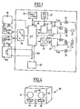
- FIG. 1 shows the essential components for realizing a control and Control device for controlling the exposure and transport speed of a motion picture film in a motion picture camera.
- a film transport motor 26 controlled by an amplifier 24 is provided for transporting the motion picture film, which is connected to a corresponding gripper switching mechanism via a gear.
- the drive shaft of the film transport motor 26 is fixedly connected to an angle encoder disc 27, so that the rotational speed or frequency and, if appropriate, the exact position of the film transport motor 26 can be detected by means of an opto-electronic position sensing device and can be passed on to a speed controller 23 via an amplifier 25.
- the actual value f is the transport speed is fed to both the speed controller 23 and a central processor 16.
- the speed controller 23 is additionally f with a target value of the transport speed is applied.
- This setpoint value is output by a synthesizer 22, the inputs of which are connected both to an oscillator 21, which outputs a reference frequency f ref to the synthesizer 22, and to an output of the central processor 16.
- the reference frequency f to the transport speed is also fed back to an input of the central processor sixteenth
- the speed controller 23 performs both a speed control depending on that emitted by the synthesizer Control value and a phase comparison between the actual value and the target value of the phase angle by.
- a setpoint value of the aperture opening angle V soll is output by the central processor 16 via a digital / analog converter 14 to a position controller 13 which is additionally acted upon by an actual value Vactual of the aperture opening angle.
- the position controller controls a diaphragm adjustment motor 3, which is preferably connected to the circulating diaphragm shaft, rotates with the circulating diaphragm and, with appropriate control by the position controller, causes a relative movement of the diaphragm adjusting wing with respect to the rotating circulating diaphragm.
- the diaphragm adjustment vane is connected to a potentiometer 6, which outputs a signal corresponding to the position of the diaphragm adjustment vane with respect to the rotating diaphragm, both at standstill and during operation, to the position controller 13 via a second amplifier 12.
- an optical sensor 20 can be arranged in the area of the adjustable orifice plate, which detects the respective aperture opening angle in the course of the adjustable orifice plate, i.e. the opening time of the orifice plate is detected and passed on to a further input of the central processor 16, so that system tolerances are eliminated and an additional comparison input in digital form to the central processor 16 is accomplished.
- the central processor 16 is connected to a memory 29, which preferably consists of a read-only memory and a There is random access memory.
- An additional input of the central processor 16 is via a multiplexer 28 with an external remote control unit 30; 181, 182, 183, via which set values for the transport speed and the aperture opening angle can be set, which are triggered by means of a program button 33 on the remote control unit or a program button 185 on the motion picture camera.
- the central processor 16 can be connected to a programming device 19 via a serial or parallel interface, with which setpoints of the transport speed and the aperture opening angle can be preprogrammed.
- the preprogrammed data preferably contain start and end values of the transport speed and the aperture opening angle as well as the time within which the change is to take place.
- the data entered by means of the programming device 19 are stored in the memory 29 and triggered with the program button 185 on the motion picture camera or the program button 33 on the remote control unit as a sequence of program steps of different transport speeds and different aperture angles.
- both the aperture angle and the transport speed can be changed.
- the at the power sources of the remote control unit 30; Values set to 181, 182, 183 are sent to the central processor via an analog / digital converter 16 emitted, which forwards the digital value of the aperture angle to the digital / analog converter 14 for regulating the aperture angle.
- the central processor 16 likewise receives a value of the transport speed via analog / digital converters, with which it sets the downstream synthesizer 22 in a stable manner with a fixed digital value.
- the synthesizer 22 is a controller which is supplied with a quartz-stable reference frequency output by the oscillator 21 and which thus regulates the transport speed. As a result of a manual adjustment of the transport speed, the current intensity emitted by the current source of the external remote control unit is converted into digital values, so that quartz-stable regulation via the synthesizer 22 is possible.
- a voltage / frequency converter can of course also be used.
- the respective aperture opening angle can be calculated in the central processor 16 by the values of each speed detected by the optical sensor, so that the aperture opening angle can also be checked and, if necessary, corrected during the run-up phase.
- FIG. 2 shows an example of a program sequence with different transport speeds and different diaphragm opening angles as a function of a predefined setpoint change.
- the program step shown in Figure 2 shows the time t0 to an initial set value of the shutter aperture angle of V to eg. 90 ° and an initial target value of the transport speed of f to example. 25 frames per second.
- a change in the transport speed and the shutter aperture is triggered t0 at the time that in an end setpoint should of eg. 180 ° for the set value of the shutter aperture V and f a target value of the transport speed is of, for example, 50 frames per second, opens, at the time t1 is reached.
- the predetermined time period ⁇ t for changing the transport speed and the aperture opening angle is, for example, 20 seconds.
- further program steps can be triggered, for example a further increase in the transport speed with an increased increase in the transport speed with an enlarged aperture opening angle or a reduction in the transport speed and aperture aperture angle also below the initial setpoint value shown in FIG. 2 of, for example, 90 ° Aperture angle and 25 frames per second transport speed.
- a setting of default values for any can be made regardless of the transport speed Aperture opening angles take place, for example when special effects are to be achieved or when the recording objects are filmed with different light sources.
- Figure 3 shows a schematic perspective view of the adjustable orifice plate, which consists of a one-piece orifice mirror plate 2, which is fixedly connected to the orifice plate shaft 1, and an adjustable orifice plate 4, which is connected via an adjustment axis 30 to an adjusting motor connected to the orifice plate shaft 1 3 is coupled.
- the circulating diaphragm shaft 1 has five slip ring contacts 10, which are used to transmit the voltage supply to the adjusting motor 3 and to transmit a measured value representing the position of the diaphragm adjusting vane 4 in relation to the circulating diaphragm 2.
- the adjustment motor 3 To adjust the aperture or the aperture adjustment sector of the motion picture camera, the adjustment motor 3 must bring about a relative movement between the peripheral aperture 2 and the aperture adjustment wing 4. This is achieved in that the adjusting motor 3 is supplied with a corresponding voltage driving it via the slip ring contacts 10, the polarity of which specifies the direction of the adjustment of the diaphragm adjustment wing to a larger or smaller diaphragm opening.
- Two of the five slip ring contacts are connected to the adjusting motor 3 and to the output of a first amplifier 11, the input of which is connected to the central processor 16 via a PID controller 13 and a digital / analog converter 14.
- the three remaining slip ring contacts 10 are connected on the one hand to a detection device for detecting the aperture opening angle, and on the other hand to the input aperture angle and on the other hand to the input of a second amplifier 12, the output of which is connected both to an analog / digital converter 15 and to the PID controller 13 connected is.
- An analog control device 18 is connected to the analog / digital converter 15.
- the output of the analog / digital converter 15 is connected to an input of the central processor 16, which is connected via further inputs to the programming device 19 and to a light barrier 20 which is arranged in the region of the adjustable orifice plate 2, 4.
- Another output of the central processor 16 is connected to a display device 17.
- a corresponding value is set on the analog control device 18 or specified via the programming device 19, which, for example, specifies a change in the aperture depending on the transport speed of the motion picture camera in the form of a ramp-shaped adjustment curve.
- the predetermined setpoint is output via the digital / analog converter 14 and the PID controller 13 and the first amplifier 11 to the slip ring contacts 10 connected to the adjusting motor 3, so that a corresponding change in the voltage supply to the adjusting motor 3 compares a relative movement of the diaphragm adjustment wing 4 the Circulating aperture 2 causes.
- the adjusting motor 3 executes a relative movement to the rotating circulating diaphragm shaft 1 and thereby moves the diaphragm adjusting wing 4 in the direction of a larger or smaller sector and thus in the direction of a larger or smaller diaphragm opening.
- a detection device coupled to the orifice plate 2 and the orifice plate 4 gives a signal corresponding to the respective position of the orifice plate 4 in relation to the orifice plate 2 via three of the five slip ring contacts 10 to the second amplifier 12 and to the analog / digital converter 15 at an input of the central processor 16, which on the one hand displays the respective angular position of the diaphragm adjustment wing 4 on the display device 17 or, in conjunction with the default value given by the analog operating device 18 or the programming device 19, feeds the target / actual value comparison.
- the additional arrangement of a light barrier in the area of the orifice plate 2 causes a measurement of the opening time of the orifice plate 2 during its run by the central processor 16 and an additional target / actual value comparison, so that a fine correction is made, which leads to the accuracy of the aperture adjustment is ensured regardless of any system tolerances.
- the aperture of the motion picture camera can be adjusted manually, automatically in conjunction with, for example Exposure meter or programmed according to a predetermined sequence program. In this way it is possible to adapt the aperture to the respective lighting conditions, to achieve certain desired effects or to adapt the aperture and thus the exposure time of the motion picture film to the respective film speed.
- FIG. 4 shows a remote control unit for connection to a motion picture camera for setting default values for the transport speed and the aperture opening angle, and for triggering predetermined and stored program steps.
- the remote control unit 30 shown schematically in perspective in FIG. 4 is connected to a motion picture camera via a connecting cable (not shown in more detail) or via an infrared ultrasound or radio transmitter and receiver.
- the remote control unit 30 can also be part of a motion picture camera or can be used as a module in a motion picture camera or can be connected to a motion picture camera.
- the remote control unit 30 is used to set default values for the transport speed and the aperture opening angle, and optionally to trigger predetermined and stored program steps.
- the remote control unit 30 contains two control buttons 31, 32, which have rotary potentiometers for setting a preset value for the transport speed and the aperture opening angle are connected, which control the current sources 38, 39 shown in Figure 1, so that different default values of the transport speed and the aperture angle are given as current values.
- a program key 33, 185 which can also be arranged on the programming device 19, is used to activate a stored program when the motion picture camera is not in the recording mode or to delete a stored program when it is pressed twice.
- the program key 33 is used to activate a predetermined program step, so that, for example, a switchover is made from the initial target values for the transport speed and the aperture opening angle to a subsequent final value within a predetermined change of the default values.
- the next program step is triggered by pressing the program button 33 again.
- An activation button 34 is used to bring the motion picture camera from a standstill into the film recording mode, so that either the preset values of the transport speed or the aperture angle set on the control buttons 31, 32 are set or a program step is triggered.
- An intermediate wheel arranged between the two control buttons 31, 32 for setting the transport speed and the aperture angle serves for the mechanical coupling of the two control buttons 31, 32, so that when the intermediate wheel is actuated, both control buttons are adjusted uniformly synchronously. In this way, a forced coupling is brought about, in which the default values for the transport speed and the aperture opening angle are changed at the same time. This ensures a constant exposure over the entire speed range of the motion picture camera and at the same time enables simplified operation, in which only one control element, namely either the idler gear or one of the two control buttons 31, 32, is to be operated in order to change the transport speed or the aperture opening angle bring about.
- the intermediate wheel is axially displaceable so that in a lower position only a common adjustment of the control buttons 31, 32 for setting the default values for the transport speed and the aperture opening angle is possible via suitable rotary potentiometers connected to the control buttons 31, 32, while in an upper one Position in which the idler gear axially from the surface of the remote control unit 30 is removed, the control buttons 31, 32 are released, so that a separate adjustment of the default values for the transport speed and the aperture angle is possible.
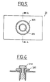
- FIG. 5 shows a plan view of a coaxial arrangement of two control buttons 31, 32 connected with rotary potentiometers
- FIG. 6 a section along the line AA according to FIG. 5 shows the embodiment with the coaxial control buttons 31, 32 in which the connection of both control buttons and thus the coupling of both potentiometers connected to the control buttons 31, 32 is carried out by lifting the upper control button 31, so that the lower control button 32 is coupled to the upper control button 31 by a force-locking connection and, when the upper control button 31 is rotated, the lower control button 32 is forced to Performs rotary motion.
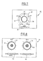
- Figure 7 shows a plan view of a remote control unit 30 with an electrical or electronic coupling of the actuators for setting the default values of the transport speed and the aperture angle.
- control button 39 is provided, with which the setpoint for the transport speed and the aperture opening angle can be adjusted either separately or synchronously.
- An additional switch 38 arranged on the user interface of the remote control unit 30 is designed as a three-pole switch and, depending on the switch position, enables the adjustment of the default values for the transport speed VSU, the change of the default value of the aperture angle SCU and the common adjustment of both default values AUTO for setting a constant exposure time.
- two scales 40, 41 are arranged around the operating button 39, which have values for the transport speed and the aperture opening angle.
- one or the other scale 40, 41 for displaying and setting the desired transport speed or the desired aperture opening angle applies when the switch 38 is in a corresponding position.
- the values for the transport speed and the aperture opening angle can be adjusted in such a way that the operating button 39 engages at predetermined values, so that special setting values are specified at these points. In the case of a continuous adjustment, the values in between can be adjusted without latching elements, so that any value setting between the minimum and maximum transport speed and the minimum and maximum aperture opening angle is possible.
- FIG. 8 shows a top view of an alternative embodiment of the electrical or electronic coupling of the potentiometers.
- two separate potentiometers with adjusting buttons 51, 54 for the transport speed VSU and the aperture opening angle SCU as well as two switches 53, 56 assigned to the two potentiometers are provided, of which one switch 53, assigned to the potentiometer for the transport speed VSU, as a three-pole Switch is executed, while the other switch 56 assigned to the potentiometer for the aperture angle SCU is a two-pole on and off switch.
Landscapes
- Physics & Mathematics (AREA)
- General Physics & Mathematics (AREA)
- Exposure Control For Cameras (AREA)
Abstract
Claims (12)
- Dispositif de commande et de réglage pour la vitesse de transport d'un film ainsi que pour l'angle d'ouverture de l'obturateur d'un obturateur rotatif (2) dans une caméra cinématographique, avec un dispositif (19) pour introduire et mettre en mémoire des données pour la programmation d'une séquence de prises de vues, dans lequel les données comprennent les valeurs finales et initiale de la vitesse de transport, le temps de transition de la valeur initiale à la valeur finale ainsi que l'angle d'ouverture de l'obturateur , et dans lequel l'angle d'ouverture de l'obturateur peut être modifié pendant la séquence de prises de vues pour maintenir l'éclairement constant,
caractérisé en ce que le dispositif (19) est conçu pour la programmation de plusieurs séquences cinématographiques, en ce qu'un processeur central (16) est prévu pour réaliser les modes de fonctionnement suivants de la caméra :(a) prises de vues avec réglage de l'angle d'ouverture de l'obturateur et de la vitesse de transport, de manière variable et indépendamment l'une de l'autre.(b) prises de vues avec vitesse de transport variable et angle d'ouverture de l'obturateur constant;(c) prises de vues avec vitesse de transport constante et angle d'ouverture de l'obturateur variable;(d) prises de vues avec vitesse de transport variable et avec adaptation de l'angle d'ouverture de l'obturateur pour maintenir l'éclairement constant,et en ce que des moyens (29, 33) sont prévus pour choisir au moins un des modes de fonctionnement, ainsi que des moyens (181, 182) pour introduire l'angle d'ouverture de l'obturateur et la vitesse de transport suivant des valeurs différant de la séquence de prises de vues programmée. - Dispositif de commande et de réglage selon la revendication 1, caractérisé en ce que le dispositif de programmation se présente sous forme d'un appareil de programmation externe (19).
- Dispositif de commande et de réglage selon la revendication 2,caractérisé en ce qu'il est prévu,pour le choix d'une séquence de prises de vues mises en mémoire,soit une touche (185) sur la caméra cinématographique, soit une unité de télécommande (30, 183) pouvant être connectée à la caméra cinématographique.
- Dispositif de commande et de réglage selon l'une des revendications précédentes, caractérisé en ce qu'il est prévu des moyens pour provoquer plusieurs séquences cinématographiques successives.
- Dispositif de commande et de réglage selon l'une des revendications précédentes, caractérisé en ce qu'une valeur de consigne (Vsoll) pour l'angle d'ouverture de l'obturateur est appliquée à un régulateur de position (13) et une valeur de consigne (fsoll) pour la vitesse de transport à un régulateur de vitesse de rotation (23), en fonction des valeurs prédéterminées introduites dans le processeur central (16) pour la vitesse de transport et pour l'angle d'ouverture de l'obturateur.
- Dispositif de commande et de réglage selon la revendication 5, caractérisé en ce que le régulateur de position (13) reçoit une valeur réelle (Vist) déterminée pour l'obturateur rotatif (2) et envoie, en fonction de l'écart de réglage, un signal de réglage au moteur de réglage (3) commandant l'obturateur rotatif (2), et en ce que le régulateur de vitesse de rotation (23) reçoit un signal de valeur réelle (fist) de la vitesse de transport et envoie au moteur de transport de film (26) un signal de réglage en fonction de l'écart de réglage.
- Dispositif de commande et de réglage selon la revendication 6, caractérisé en ce qu'un synthétiseur (22) reçoit un signal de valeur réelle (fist) de la vitesse de transport ainsi que la valeur de consigne (fsoll) fournie par le processeur central (16) pour la vitesse de transport et une fréquence de référence (fref) fournie par un oscillateur (21) et règle la vitesse de transport en envoyant une valeur de consigne (fsoll) au régulateur de vitesse de régulation (23).
- Dispositif de commande et de réglage selon l'une des revendications 2, 5 ou 6, caractérisé en ce que l'appareil de programmation externe (19) peut être connecté par une interface au processeur central (16) qui envoie les données de la séquence de prises de vues dans une mémoire (29) et qui, lorsqu'on actionne une touche de déclenchement, les fournit au synthétiseur (22) ou, par un convertisseur numérique/analogique (14), au régulateur de position (13).
- Dispositif de commande et de réglage selon l'une des revendications 3 à 8, caractérisé en ce que l'unité de télécommande (30, 181 à 183) est connectée à la caméra cinématographique par un câble de liaison ou par un dispositif émetteur et récepteur à infrarouges, à ultrasons ou radiophonique et présente au moins un commutateur (35, 36) pour choisir le déroulement du programme de la caméra cinématographique, une touche de programmation (33) pour provoquer le déroulement du programme mis en mémoire ou la valeur prédéterminée introduite dans l'unité de télécomande (30, 181, 182, 183) pour la vitesse de transport et pour l'angle d'ouverture de l'obturateur, ainsi que des éléments de réglage (31, 32) servant de moyens pour introduire des valeurs de l'angle d'ouverture de l'obturateur et de la vitese de transport différant du déroulement du programme choisi.
- Dispositif de commande et de réglage selon la revendication 9, caractérisé en ce que les éléments de réglage (31, 32) sont constitués de potentiomètres disposés les uns à côté des autres ou coaxialement.
- Dispositif de commande et de réglage selon la revendication 10, caractérisé en ce que l'unité de télécommande (30; 181 à 183) présente des commutateurs correspondant aux potentiomètres, dont un premier commutateur (53) est de type tripolaire et rend inactif un potentiomètre dans une première position, rend actif un potentiomètre dans une deuxième position et, dans une troisième position, réalise un couplage électrique des deux éléments de réglage pour réaliser un temps d'éclairement constant, tandis qu'un autre commutateur (56) correspondant à l'autre potentiomètre est de type bipolaire et rend inactif le potentiomètre correspondant dans une première position et active le potentiomètre dans la deuxième position.
- Dispositif de commande et de réglage selon la revendication 11, caractérisé en ce qu'un autre commutateur (38) parmi les commutateurs correspondant aux potentiomètres est de type tripolaire tandis que, dans une première position du commutateur (38), la valeur de consigne de la vitesse de transport (VSU) peut être réglée en synchronisme, que, dans une deuxième position du commutateur (38), c'est la valeur de consigne de l'angle d'ouverture de l'obturateur (SCU) qui est réglée en synchronisme et que, dans une troisième position (AUTO) du commutateur (38), la valeur de consigne de la vitesse de transport (VSU) et de l'angle d'ouverture de l'obturateur (SCU) peut être réglée en synchronisme.
Priority Applications (1)
| Application Number | Priority Date | Filing Date | Title |
|---|---|---|---|
| AT90901754T ATE95320T1 (de) | 1989-02-08 | 1990-01-24 | Steuer- und regeleinrichtung fuer die belichtung und transportgeschwindigkeit eines laufbildfilms in einer laufbildkamera. |
Applications Claiming Priority (4)
| Application Number | Priority Date | Filing Date | Title |
|---|---|---|---|
| DE3903625 | 1989-02-08 | ||
| DE19893903625 DE3903625A1 (de) | 1989-02-08 | 1989-02-08 | Verfahren und anordnung zur belichtungssteuerung einer laufbildkamera |
| DE3940408A DE3940408A1 (de) | 1989-02-08 | 1989-12-04 | Vorrichtung zur belichtungssteuerung einer laufbildkamera |
| DE3940408 | 1989-12-04 |
Publications (2)
| Publication Number | Publication Date |
|---|---|
| EP0457770A1 EP0457770A1 (fr) | 1991-11-27 |
| EP0457770B1 true EP0457770B1 (fr) | 1993-09-29 |
Family
ID=25877541
Family Applications (1)
| Application Number | Title | Priority Date | Filing Date |
|---|---|---|---|
| EP90901754A Expired - Lifetime EP0457770B1 (fr) | 1989-02-08 | 1990-01-24 | Dispositif pour commander et reguler l'eclairage et la vitesse d'entrainement d'un film cinematographique dans une camera |
Country Status (4)
| Country | Link |
|---|---|
| US (1) | US5223867A (fr) |
| EP (1) | EP0457770B1 (fr) |
| DE (2) | DE3940408A1 (fr) |
| WO (1) | WO1990009618A1 (fr) |
Families Citing this family (8)
| Publication number | Priority date | Publication date | Assignee | Title |
|---|---|---|---|---|
| DE4219331A1 (de) * | 1992-06-10 | 1993-12-16 | Arnold & Richter Kg | Steuersystem für eine Kamera |
| DE19629484A1 (de) * | 1996-07-12 | 1998-01-15 | Arnold & Richter Kg | Vorrichtung zur Steuerung, Regelung und Kontrolle einer Laufbildkamera |
| AU2001261284A1 (en) * | 2000-05-09 | 2001-11-20 | Jon Oshima | Multiplexed motion picture camera |
| US6724429B2 (en) | 2001-04-23 | 2004-04-20 | Panavision, Inc. | System for sensing and displaying lens data for high performance film and video cameras and lenses |
| CA2448678C (fr) | 2001-05-30 | 2008-03-25 | Panavision, Inc. | Telecommande a tenue manuelle pour cameras ou camescopes et pour lentilles |
| DE102004004806B4 (de) * | 2004-01-30 | 2012-04-19 | Arnold & Richter Cine Technik Gmbh & Co. Betriebs Kg | Elektronische Laufbildkamera |
| JP4541723B2 (ja) * | 2004-02-27 | 2010-09-08 | 株式会社リコー | モータ駆動装置、デジタルカメラ、及びモータ制御方法 |
| US7619047B2 (en) * | 2006-02-22 | 2009-11-17 | Chevron Phillips Chemical Company, Lp | Dual metallocene catalysts for polymerization of bimodal polymers |
Family Cites Families (12)
| Publication number | Priority date | Publication date | Assignee | Title |
|---|---|---|---|---|
| DE2213837C3 (de) * | 1972-03-22 | 1982-03-11 | Robert Bosch Gmbh, 7000 Stuttgart | Laufbildkamera mit einem während des Betriebs auf unterschiedliche Laufgeschwindigkeiten einstellbaren Antriebsmotor |
| JPS50119628A (fr) * | 1974-03-01 | 1975-09-19 | ||
| US4046464A (en) * | 1974-06-25 | 1977-09-06 | Canon Kabushiki Kaisha | Exposure control system and a motion picture camera using the same |
| AT347258B (de) * | 1975-01-24 | 1978-12-27 | Eumig | Laufbildkamera |
| AT353098B (de) * | 1977-11-25 | 1979-10-25 | Moviecam Kinematograph | Filmaufnahmekamera |
| JPS54108631A (en) * | 1978-02-14 | 1979-08-25 | Canon Inc | Cine camera |
| DE2832033A1 (de) * | 1978-07-21 | 1980-01-31 | Braun Ag | Steuersystem fuer eine laufbildkamera, insbesondere eine tonfilmkamera |
| DE2848676A1 (de) * | 1978-11-09 | 1980-05-22 | Moviecam Kinematograph | Einrichtung an filmaufnahmekameras |
| DE2947333A1 (de) * | 1979-11-23 | 1981-06-04 | Arnold & Richter Cine Technik GmbH & Co Betriebs KG, 8000 München | Verstellbare umlaufblende |
| US4405217A (en) * | 1981-09-01 | 1983-09-20 | Redlake Corporation | Film speed control systems for high speed motion picture cameras |
| US4458992A (en) * | 1982-09-29 | 1984-07-10 | Preston Howard J | Automatic exposure correction system |
| US4702577A (en) * | 1984-08-17 | 1987-10-27 | Dedo Weigert Film Gmbh | Film transport device |
-
1989
- 1989-12-04 DE DE3940408A patent/DE3940408A1/de active Granted
-
1990
- 1990-01-24 WO PCT/DE1990/000047 patent/WO1990009618A1/fr not_active Ceased
- 1990-01-24 EP EP90901754A patent/EP0457770B1/fr not_active Expired - Lifetime
- 1990-01-24 DE DE90901754T patent/DE59002950D1/de not_active Expired - Lifetime
-
1991
- 1991-10-08 US US07/773,045 patent/US5223867A/en not_active Expired - Lifetime
Also Published As
| Publication number | Publication date |
|---|---|
| DE3940408A1 (de) | 1991-06-13 |
| WO1990009618A1 (fr) | 1990-08-23 |
| EP0457770A1 (fr) | 1991-11-27 |
| DE59002950D1 (de) | 1993-11-04 |
| US5223867A (en) | 1993-06-29 |
Similar Documents
| Publication | Publication Date | Title |
|---|---|---|
| DE69126979T2 (de) | Abstandsbedienungssystem hauptsächlich für filmkameras und verfahren dafür | |
| EP0574105A1 (fr) | Système modulaire de commande pour caméra | |
| DE69229981T2 (de) | Überwachungsvorrichtung mit Steuerung der Kamera und der Linsemontage | |
| DE69412315T2 (de) | Optisches Abtasthandgerät mit Geschwindigkeitskontrolle | |
| DE2630135C3 (de) | Vorrichtung zum Herstellen von Röntgenschichtaufnahmen gekrümmter Flächen | |
| DE3147427A1 (de) | Abtasteinrichtung fuer fotokopiergeraet | |
| EP0457770B1 (fr) | Dispositif pour commander et reguler l'eclairage et la vitesse d'entrainement d'un film cinematographique dans une camera | |
| EP1733554A1 (fr) | Procede et dispositif pour regler la nettete d'image au niveau de l'objectif d'une camera | |
| DE69901958T2 (de) | Fokusanzeige für filmkamera mit hilfe der parallaxgeometrie von zwei videokameras | |
| CH654674A5 (de) | Vorrichtung zum fokussieren des objektivs einer filmkamera. | |
| EP0229971A1 (fr) | Appareil de radiodiagnostic dentaire pour réaliser une tomographie panoramique de la mâchoire d'un patient | |
| DE3220929C2 (fr) | ||
| DE3107075A1 (de) | Verfahren und vorrichtung zur automatischen scharfeinstellung bei einem projektionssystem mit kontinuierlich veraenderbarem abbildungsmassstab | |
| DE69114148T2 (de) | Scharfeinstellungsanordnung für eine Kamera. | |
| DE4213312A1 (de) | Operationsmikroskop | |
| DE3828284C2 (de) | Fokussiervorrichtung für eine Kamera und ein Verfahren zum Betreiben dieser Vorrichtung | |
| CH654673A5 (de) | Vorrichtung zum fokussieren des objektivs einer filmkamera. | |
| DE2359572B2 (de) | Einrichtung zur steuerung eines antriebsmechanismus fuer die einstellung eines aufnahmeparameters an einer fotografischen kamera | |
| DE68908888T2 (de) | Automatische objektivselektion für ein gewünschtes optisches reduktionsverhältnis in einer mikrofilmkamera. | |
| DE3903625C2 (fr) | ||
| DE69116223T2 (de) | Antriebssteuerungsgerät für optisches Kamerasystem | |
| DE3010798C2 (de) | Vorrichtung zum Steuern der Transportgeschwindigkeit des Röntgenfilms bei einer zahnärztlichen Röntgeneinrichtung | |
| DE2947333C2 (fr) | ||
| DE69936276T2 (de) | Optische Vorrichtung | |
| DE3010799C2 (de) | Zahnärztliche Röntgenvorrichtung zum Herstellen von Röntgenaufnahmen des gesamten Kiefers |
Legal Events
| Date | Code | Title | Description |
|---|---|---|---|
| PUAI | Public reference made under article 153(3) epc to a published international application that has entered the european phase |
Free format text: ORIGINAL CODE: 0009012 |
|
| 17P | Request for examination filed |
Effective date: 19910807 |
|
| AK | Designated contracting states |
Kind code of ref document: A1 Designated state(s): AT CH DE FR GB IT LI |
|
| 17Q | First examination report despatched |
Effective date: 19921123 |
|
| GRAA | (expected) grant |
Free format text: ORIGINAL CODE: 0009210 |
|
| AK | Designated contracting states |
Kind code of ref document: B1 Designated state(s): AT CH DE FR GB IT LI |
|
| REF | Corresponds to: |
Ref document number: 95320 Country of ref document: AT Date of ref document: 19931015 Kind code of ref document: T |
|
| REF | Corresponds to: |
Ref document number: 59002950 Country of ref document: DE Date of ref document: 19931104 |
|
| GBT | Gb: translation of ep patent filed (gb section 77(6)(a)/1977) |
Effective date: 19931115 |
|
| ITF | It: translation for a ep patent filed | ||
| ET | Fr: translation filed | ||
| PLBE | No opposition filed within time limit |
Free format text: ORIGINAL CODE: 0009261 |
|
| STAA | Information on the status of an ep patent application or granted ep patent |
Free format text: STATUS: NO OPPOSITION FILED WITHIN TIME LIMIT |
|
| 26N | No opposition filed | ||
| PGFP | Annual fee paid to national office [announced via postgrant information from national office to epo] |
Ref country code: CH Payment date: 20000119 Year of fee payment: 11 |
|
| PG25 | Lapsed in a contracting state [announced via postgrant information from national office to epo] |
Ref country code: LI Free format text: LAPSE BECAUSE OF NON-PAYMENT OF DUE FEES Effective date: 20010131 Ref country code: CH Free format text: LAPSE BECAUSE OF NON-PAYMENT OF DUE FEES Effective date: 20010131 |
|
| REG | Reference to a national code |
Ref country code: CH Ref legal event code: PL |
|
| PGFP | Annual fee paid to national office [announced via postgrant information from national office to epo] |
Ref country code: AT Payment date: 20011221 Year of fee payment: 13 |
|
| REG | Reference to a national code |
Ref country code: GB Ref legal event code: IF02 |
|
| PGFP | Annual fee paid to national office [announced via postgrant information from national office to epo] |
Ref country code: FR Payment date: 20020129 Year of fee payment: 13 |
|
| PG25 | Lapsed in a contracting state [announced via postgrant information from national office to epo] |
Ref country code: AT Free format text: LAPSE BECAUSE OF NON-PAYMENT OF DUE FEES Effective date: 20030124 |
|
| PG25 | Lapsed in a contracting state [announced via postgrant information from national office to epo] |
Ref country code: FR Free format text: LAPSE BECAUSE OF NON-PAYMENT OF DUE FEES Effective date: 20030930 |
|
| REG | Reference to a national code |
Ref country code: FR Ref legal event code: ST |
|
| PG25 | Lapsed in a contracting state [announced via postgrant information from national office to epo] |
Ref country code: IT Free format text: LAPSE BECAUSE OF NON-PAYMENT OF DUE FEES;WARNING: LAPSES OF ITALIAN PATENTS WITH EFFECTIVE DATE BEFORE 2007 MAY HAVE OCCURRED AT ANY TIME BEFORE 2007. THE CORRECT EFFECTIVE DATE MAY BE DIFFERENT FROM THE ONE RECORDED. Effective date: 20050124 |
|
| PGFP | Annual fee paid to national office [announced via postgrant information from national office to epo] |
Ref country code: DE Payment date: 20081128 Year of fee payment: 20 |
|
| PGFP | Annual fee paid to national office [announced via postgrant information from national office to epo] |
Ref country code: GB Payment date: 20090123 Year of fee payment: 20 |
|
| REG | Reference to a national code |
Ref country code: GB Ref legal event code: PE20 Expiry date: 20100123 |
|
| PG25 | Lapsed in a contracting state [announced via postgrant information from national office to epo] |
Ref country code: GB Free format text: LAPSE BECAUSE OF EXPIRATION OF PROTECTION Effective date: 20100123 |
|
| PG25 | Lapsed in a contracting state [announced via postgrant information from national office to epo] |
Ref country code: DE Free format text: LAPSE BECAUSE OF EXPIRATION OF PROTECTION Effective date: 20100124 |