EP0457801B1 - Vorrichtung für ein radarniveaumessgerät - Google Patents
Vorrichtung für ein radarniveaumessgerät Download PDFInfo
- Publication number
- EP0457801B1 EP0457801B1 EP90902860A EP90902860A EP0457801B1 EP 0457801 B1 EP0457801 B1 EP 0457801B1 EP 90902860 A EP90902860 A EP 90902860A EP 90902860 A EP90902860 A EP 90902860A EP 0457801 B1 EP0457801 B1 EP 0457801B1
- Authority
- EP
- European Patent Office
- Prior art keywords
- waveguide
- tube
- microwave signal
- section
- plane
- Prior art date
- Legal status (The legal status is an assumption and is not a legal conclusion. Google has not performed a legal analysis and makes no representation as to the accuracy of the status listed.)
- Expired - Lifetime
Links
Images



Classifications
-
- G—PHYSICS
- G01—MEASURING; TESTING
- G01S—RADIO DIRECTION-FINDING; RADIO NAVIGATION; DETERMINING DISTANCE OR VELOCITY BY USE OF RADIO WAVES; LOCATING OR PRESENCE-DETECTING BY USE OF THE REFLECTION OR RERADIATION OF RADIO WAVES; ANALOGOUS ARRANGEMENTS USING OTHER WAVES
- G01S7/00—Details of systems according to groups G01S13/00, G01S15/00, G01S17/00
- G01S7/02—Details of systems according to groups G01S13/00, G01S15/00, G01S17/00 of systems according to group G01S13/00
- G01S7/024—Details of systems according to groups G01S13/00, G01S15/00, G01S17/00 of systems according to group G01S13/00 using polarisation effects
- G01S7/025—Details of systems according to groups G01S13/00, G01S15/00, G01S17/00 of systems according to group G01S13/00 using polarisation effects involving the transmission of linearly polarised waves
-
- G—PHYSICS
- G01—MEASURING; TESTING
- G01S—RADIO DIRECTION-FINDING; RADIO NAVIGATION; DETERMINING DISTANCE OR VELOCITY BY USE OF RADIO WAVES; LOCATING OR PRESENCE-DETECTING BY USE OF THE REFLECTION OR RERADIATION OF RADIO WAVES; ANALOGOUS ARRANGEMENTS USING OTHER WAVES
- G01S7/00—Details of systems according to groups G01S13/00, G01S15/00, G01S17/00
- G01S7/02—Details of systems according to groups G01S13/00, G01S15/00, G01S17/00 of systems according to group G01S13/00
- G01S7/40—Means for monitoring or calibrating
-
- F—MECHANICAL ENGINEERING; LIGHTING; HEATING; WEAPONS; BLASTING
- F17—STORING OR DISTRIBUTING GASES OR LIQUIDS
- F17C—VESSELS FOR CONTAINING OR STORING COMPRESSED, LIQUEFIED OR SOLIDIFIED GASES; FIXED-CAPACITY GAS-HOLDERS; FILLING VESSELS WITH, OR DISCHARGING FROM VESSELS, COMPRESSED, LIQUEFIED, OR SOLIDIFIED GASES
- F17C13/00—Details of vessels or of the filling or discharging of vessels
- F17C13/02—Special adaptations of indicating, measuring, or monitoring equipment
- F17C13/021—Special adaptations of indicating, measuring, or monitoring equipment having the height as the parameter
-
- G—PHYSICS
- G01—MEASURING; TESTING
- G01F—MEASURING VOLUME, VOLUME FLOW, MASS FLOW OR LIQUID LEVEL; METERING BY VOLUME
- G01F23/00—Indicating or measuring liquid level or level of fluent solid material, e.g. indicating in terms of volume or indicating by means of an alarm
- G01F23/22—Indicating or measuring liquid level or level of fluent solid material, e.g. indicating in terms of volume or indicating by means of an alarm by measuring physical variables, other than linear dimensions, pressure or weight, dependent on the level to be measured, e.g. by difference of heat transfer of steam or water
- G01F23/28—Indicating or measuring liquid level or level of fluent solid material, e.g. indicating in terms of volume or indicating by means of an alarm by measuring physical variables, other than linear dimensions, pressure or weight, dependent on the level to be measured, e.g. by difference of heat transfer of steam or water by measuring the variations of parameters of electromagnetic or acoustic waves applied directly to the liquid or fluent solid material
- G01F23/284—Electromagnetic waves
-
- G—PHYSICS
- G01—MEASURING; TESTING
- G01S—RADIO DIRECTION-FINDING; RADIO NAVIGATION; DETERMINING DISTANCE OR VELOCITY BY USE OF RADIO WAVES; LOCATING OR PRESENCE-DETECTING BY USE OF THE REFLECTION OR RERADIATION OF RADIO WAVES; ANALOGOUS ARRANGEMENTS USING OTHER WAVES
- G01S13/00—Systems using the reflection or reradiation of radio waves, e.g. radar systems; Analogous systems using reflection or reradiation of waves whose nature or wavelength is irrelevant or unspecified
- G01S13/88—Radar or analogous systems specially adapted for specific applications
-
- F—MECHANICAL ENGINEERING; LIGHTING; HEATING; WEAPONS; BLASTING
- F17—STORING OR DISTRIBUTING GASES OR LIQUIDS
- F17C—VESSELS FOR CONTAINING OR STORING COMPRESSED, LIQUEFIED OR SOLIDIFIED GASES; FIXED-CAPACITY GAS-HOLDERS; FILLING VESSELS WITH, OR DISCHARGING FROM VESSELS, COMPRESSED, LIQUEFIED, OR SOLIDIFIED GASES
- F17C2221/00—Handled fluid, in particular type of fluid
- F17C2221/03—Mixtures
-
- F—MECHANICAL ENGINEERING; LIGHTING; HEATING; WEAPONS; BLASTING
- F17—STORING OR DISTRIBUTING GASES OR LIQUIDS
- F17C—VESSELS FOR CONTAINING OR STORING COMPRESSED, LIQUEFIED OR SOLIDIFIED GASES; FIXED-CAPACITY GAS-HOLDERS; FILLING VESSELS WITH, OR DISCHARGING FROM VESSELS, COMPRESSED, LIQUEFIED, OR SOLIDIFIED GASES
- F17C2221/00—Handled fluid, in particular type of fluid
- F17C2221/03—Mixtures
- F17C2221/032—Hydrocarbons
- F17C2221/033—Methane, e.g. natural gas, CNG, LNG, GNL, GNC, PLNG
-
- F—MECHANICAL ENGINEERING; LIGHTING; HEATING; WEAPONS; BLASTING
- F17—STORING OR DISTRIBUTING GASES OR LIQUIDS
- F17C—VESSELS FOR CONTAINING OR STORING COMPRESSED, LIQUEFIED OR SOLIDIFIED GASES; FIXED-CAPACITY GAS-HOLDERS; FILLING VESSELS WITH, OR DISCHARGING FROM VESSELS, COMPRESSED, LIQUEFIED, OR SOLIDIFIED GASES
- F17C2221/00—Handled fluid, in particular type of fluid
- F17C2221/03—Mixtures
- F17C2221/032—Hydrocarbons
- F17C2221/035—Propane butane, e.g. LPG, GPL
-
- F—MECHANICAL ENGINEERING; LIGHTING; HEATING; WEAPONS; BLASTING
- F17—STORING OR DISTRIBUTING GASES OR LIQUIDS
- F17C—VESSELS FOR CONTAINING OR STORING COMPRESSED, LIQUEFIED OR SOLIDIFIED GASES; FIXED-CAPACITY GAS-HOLDERS; FILLING VESSELS WITH, OR DISCHARGING FROM VESSELS, COMPRESSED, LIQUEFIED, OR SOLIDIFIED GASES
- F17C2223/00—Handled fluid before transfer, i.e. state of fluid when stored in the vessel or before transfer from the vessel
- F17C2223/01—Handled fluid before transfer, i.e. state of fluid when stored in the vessel or before transfer from the vessel characterised by the phase
- F17C2223/0146—Two-phase
- F17C2223/0153—Liquefied gas, e.g. LPG, GPL
-
- F—MECHANICAL ENGINEERING; LIGHTING; HEATING; WEAPONS; BLASTING
- F17—STORING OR DISTRIBUTING GASES OR LIQUIDS
- F17C—VESSELS FOR CONTAINING OR STORING COMPRESSED, LIQUEFIED OR SOLIDIFIED GASES; FIXED-CAPACITY GAS-HOLDERS; FILLING VESSELS WITH, OR DISCHARGING FROM VESSELS, COMPRESSED, LIQUEFIED, OR SOLIDIFIED GASES
- F17C2223/00—Handled fluid before transfer, i.e. state of fluid when stored in the vessel or before transfer from the vessel
- F17C2223/03—Handled fluid before transfer, i.e. state of fluid when stored in the vessel or before transfer from the vessel characterised by the pressure level
- F17C2223/033—Small pressure, e.g. for liquefied gas
-
- F—MECHANICAL ENGINEERING; LIGHTING; HEATING; WEAPONS; BLASTING
- F17—STORING OR DISTRIBUTING GASES OR LIQUIDS
- F17C—VESSELS FOR CONTAINING OR STORING COMPRESSED, LIQUEFIED OR SOLIDIFIED GASES; FIXED-CAPACITY GAS-HOLDERS; FILLING VESSELS WITH, OR DISCHARGING FROM VESSELS, COMPRESSED, LIQUEFIED, OR SOLIDIFIED GASES
- F17C2223/00—Handled fluid before transfer, i.e. state of fluid when stored in the vessel or before transfer from the vessel
- F17C2223/03—Handled fluid before transfer, i.e. state of fluid when stored in the vessel or before transfer from the vessel characterised by the pressure level
- F17C2223/035—High pressure (>10 bar)
-
- F—MECHANICAL ENGINEERING; LIGHTING; HEATING; WEAPONS; BLASTING
- F17—STORING OR DISTRIBUTING GASES OR LIQUIDS
- F17C—VESSELS FOR CONTAINING OR STORING COMPRESSED, LIQUEFIED OR SOLIDIFIED GASES; FIXED-CAPACITY GAS-HOLDERS; FILLING VESSELS WITH, OR DISCHARGING FROM VESSELS, COMPRESSED, LIQUEFIED, OR SOLIDIFIED GASES
- F17C2250/00—Accessories; Control means; Indicating, measuring or monitoring of parameters
- F17C2250/03—Control means
- F17C2250/034—Control means using wireless transmissions
-
- F—MECHANICAL ENGINEERING; LIGHTING; HEATING; WEAPONS; BLASTING
- F17—STORING OR DISTRIBUTING GASES OR LIQUIDS
- F17C—VESSELS FOR CONTAINING OR STORING COMPRESSED, LIQUEFIED OR SOLIDIFIED GASES; FIXED-CAPACITY GAS-HOLDERS; FILLING VESSELS WITH, OR DISCHARGING FROM VESSELS, COMPRESSED, LIQUEFIED, OR SOLIDIFIED GASES
- F17C2250/00—Accessories; Control means; Indicating, measuring or monitoring of parameters
- F17C2250/04—Indicating or measuring of parameters as input values
- F17C2250/0404—Parameters indicated or measured
- F17C2250/0408—Level of content in the vessel
- F17C2250/0417—Level of content in the vessel with electrical means
-
- F—MECHANICAL ENGINEERING; LIGHTING; HEATING; WEAPONS; BLASTING
- F17—STORING OR DISTRIBUTING GASES OR LIQUIDS
- F17C—VESSELS FOR CONTAINING OR STORING COMPRESSED, LIQUEFIED OR SOLIDIFIED GASES; FIXED-CAPACITY GAS-HOLDERS; FILLING VESSELS WITH, OR DISCHARGING FROM VESSELS, COMPRESSED, LIQUEFIED, OR SOLIDIFIED GASES
- F17C2260/00—Purposes of gas storage and gas handling
- F17C2260/02—Improving properties related to fluid or fluid transfer
- F17C2260/024—Improving metering
-
- F—MECHANICAL ENGINEERING; LIGHTING; HEATING; WEAPONS; BLASTING
- F17—STORING OR DISTRIBUTING GASES OR LIQUIDS
- F17C—VESSELS FOR CONTAINING OR STORING COMPRESSED, LIQUEFIED OR SOLIDIFIED GASES; FIXED-CAPACITY GAS-HOLDERS; FILLING VESSELS WITH, OR DISCHARGING FROM VESSELS, COMPRESSED, LIQUEFIED, OR SOLIDIFIED GASES
- F17C2270/00—Applications
- F17C2270/01—Applications for fluid transport or storage
- F17C2270/0102—Applications for fluid transport or storage on or in the water
- F17C2270/0105—Ships
-
- Y—GENERAL TAGGING OF NEW TECHNOLOGICAL DEVELOPMENTS; GENERAL TAGGING OF CROSS-SECTIONAL TECHNOLOGIES SPANNING OVER SEVERAL SECTIONS OF THE IPC; TECHNICAL SUBJECTS COVERED BY FORMER USPC CROSS-REFERENCE ART COLLECTIONS [XRACs] AND DIGESTS
- Y10—TECHNICAL SUBJECTS COVERED BY FORMER USPC
- Y10S—TECHNICAL SUBJECTS COVERED BY FORMER USPC CROSS-REFERENCE ART COLLECTIONS [XRACs] AND DIGESTS
- Y10S367/00—Communications, electrical: acoustic wave systems and devices
- Y10S367/908—Material level detection, e.g. liquid level
Definitions
- the present invention relates to a device for gauging the level of a fluid in a container as set out in the preamble of claim 1.
- Such devices have become more and more important particularly for petroleum products such as crude oil and products manufactured therefrom.
- containers it is meant in this context large containers constituting parts of the total loading volume of a tanker, or even larger usually circular-cylindrical landbased tanks with volumes of tens of thousands of cubic meters.
- Demands on accuracy of measurement have become higher.
- This has brought about, for instance, that level gauging in containers that contain condensable gas under overpressure, such as natural gas, butane or propane, places particularly high demands on the gauging equipment used.
- condensable gas under overpressure such as natural gas, butane or propane
- a device of the kind mentioned in the introduction which can be calibrated in a simple manner also when said container contains a condensable gas under overpressure, is characterized primarily by a polarization means arranged to polarize the microwave signal emitted from the transmitter in a first or a second polarisation plane, which form a mutual angle, preferably 90°, and further by at least one reflecting reactance arranged in said tube to give a substantially stronger reflection of the microwave signal in the first polarization plane than in the second.
- the said tube is usually circular-cylindrical, but other embodiments are also possible provided they show 90° symmetry in cross section, such as a square or super-elliptical cross section with two equally long major axes.
- a polarizable microwave signal such is preferably used as shows H11 mode, but also other rotary unsymmetrical modes, such as E11 mode, are conceivable.
- the cross section of the tube is often dimensioned so that it admits passage of higher modes.
- the transmitter comprises a circular waveguide for one-mode propagation, primarily for H11 mode.
- the polarization means can in a known manner be formed in many different ways.
- it consists of a substantially plane plate of a dielectric material such as a polymer, arranged with its plane substantially parallel to the symmetry axis of the waveguide, preferably crosswise filling out the diameter of the waveguide, the waveguide having suitably a circular cross section.
- the plate is arranged turnable about the symmetry axis of the waveguide between two positions, preferably so that the planes of the plate in the two positions form 45°.
- the plate of dielectric material is replaced by one or two plane metal plates, they too being placed with their planes substantially parallel to the symmetry axis of the waveguide, however not crosswise filling out the diameter of the waveguide.
- the plate or plates are correspondingly turnable.
- this is a section of a waveguide, which is oval in cross section, the waveguide section being arranged turnable about its symmetry axis optionally between two positions, preferably so that the longitudinal symmetry planes of the waveguide section in the two positions form 45°.
- the said reactance can be formed in a number of different ways.
- a suitable embodiment comprises that it is formed of a relatively thin metal pin, arranged with its longitudinal direction perpendicular to the longitudinal axis of the tube, preferably extending diametrically through the tube.
- the reactance can also be formed by an aperture in the wall of the tube, preferably with its longitudinal direction perpendicular to the longitudinal axis of the tube.
- the aperture can be made substantially bigger than said relatively small openings in the tube, but this is not necessary - at calibration such an electronic unit can be used that is provided with a suitable filter, so that the reflex position of the reactance can still be measured.
- FIG. 1 designates a vertical, circular-cylindrical tube that is rigidly mounted in a container, not shown, containing a fluid, such as a condensed gas.
- the tube is not shown in its entire length but only in its upper and lower portions.
- the tube is provided with a number of relatively small openings 2 in its wall, which makes possible the communication of the fluid from the container to the interior of the tube, so that the level of the fluid is the same in the tube as in the container.
- the upper limitation or roof of the container is designated by 3.
- This unit comprises a transmitter, not shown, for feeding a polarized microwave signal, in this case with H11 mode, and a receiver for receiving reflected microwave signals, and an electronic unit for determining the reflex position of the reflected microwave signal.
- the transmitter comprises a circular waveguide, designated by 5 in Figure 1.
- a section of this waveguide 6, consists of the polarization means, and is turnable between two positions at 45° distance from each other.
- a plane plate 7 of a polymer material diametrically filling out the section, with its plane parallel to the symmetry axis of the waveguide.
- the waveguide is surrounded by a protection tube 8.
- the waveguide 5 passes via a conical middle piece 9 over to the tube 1.
- a relatively thin metal pin 10 mounted diametrically perpendicular to the longitudinal direction of the tube 1.
- This metal pin 10 consists of a reactance which gives rise to a defined reflection of an emitted microwave signal, which is received by the receiver in the unit 4 and via the electronic unit gives a calibration of the gauging function.
- the unit 4 with the transmitter and the receiver is fixed in relation to the metal pin.
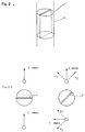
- FIG 2 A the section 6 is shown by the waveguide with the plate 7, i.e. the polarization means used.
- the polarization of an incoming microwave signal is presented schematically in the Figures 2 B arid 2 C. H11 mode is used, and the central vector of the E field above the plate 7 is designated by E. If the plate 7 is at right angles to this vector E, there is no effect on the E field, Figure 2 B. If, on the other hand, as in Figure 2 C, the plate is at 45° to the vector E, it will be turned 90°, to the direction E p under the plate.
- E is split up into the components E1 and E2. Out of these, E2 is directed parallelly to the plate and is phase-shifted 180°, while E1 remains unchanged. E p is the resultant of E1 and E3 under the plate, as mentioned, turned 90° relative to E.
- the microwave signal is emitted with the central vector of the E field perpendicular to the metal pin 10, only a relatively weak signal will be reflected to the receiver, while there is hardly any effect of the metal pin on the signal that is reflected away from the surface of the fluid if the metal pin is located near that surface. If, on the other hand, the central vector of the E field is emitted polarized 90° it will be reflected with maximum strength by the metal pin, and thereby makes a calibration gauging possible.
- Figure 3 four alternative embodiments of the polarization means are shown in two columns, schematically in cross section.
- Figure 3 A1 is a waveguide section with oval cross section that can be turned 45° for polarization of an incoming microwave signal.
- Figures 3 B1, B2 show a metal pin 12 that does not fill a circular cross section of a waveguide
- Figures 3 C1, C2 show metal plates in the form of rails 13 at the wall of a circular waveguide
- Figures 3 D1, D2 show a circular waveguide with diametrically insertable, plane metal plates 14.
- FIG. 4 Some different alternative embodiments of a reactance can be seen in Figure 4.
- the embodiment with a relatively thin metal pin 10 is shown perspectively and in cross section in Figures 4 A, and 4 B, respectively.
- Figure 5 A, B is formed as a pair of symmetrically, diametrically mounted pegs 5.
- One further proposed embodiment is a circumferential aperture 11 shown by Figures 6 A, B.
- the adjustment of the polarization means can be effected manually or through distant control completely independent of the operation conditions in the container that contains the fluid in question.
Landscapes
- Engineering & Computer Science (AREA)
- Physics & Mathematics (AREA)
- Remote Sensing (AREA)
- Radar, Positioning & Navigation (AREA)
- General Physics & Mathematics (AREA)
- Electromagnetism (AREA)
- Computer Networks & Wireless Communication (AREA)
- Mechanical Engineering (AREA)
- General Engineering & Computer Science (AREA)
- Thermal Sciences (AREA)
- Fluid Mechanics (AREA)
- Measurement Of Levels Of Liquids Or Fluent Solid Materials (AREA)
- Radar Systems Or Details Thereof (AREA)
Claims (7)
- Vorrichtung zur Messung eines Fluidpegels in einem Behälter, beispielsweise einer Flüssigkeit oder eines granulatförmigen Materials, vorzugsweise eines unter Überdruck stehenden kondensierbaren Gases, umfassend- ein vertikales Rohr (1) mit einer Mehrzahl verhältnismäßig kleiner Öffnungen in dessen Wand, um einen Durchgang des Fluids zu ermöglichen um sicherzustellen, daß der Pegel im Rohr der gleiche wie im Behälter ist,- einen Sender für die Leitung eines polarisierbaren Mikrowellensignals durch das Rohr (1), dessen Querschnitt so groß ist, daß es den Durchgang des Mikrowellensignals gestattet, sowie- eine Elektronikeinheit zur Bestimmung der Reflektionsposition des reflektierten Mikrowellensignals,gekennzeichnet durch- eine Polarisationseinrichtung (6, 7) zur Polarisierung des vom Sender in einer ersten oder zweiten Polarisationsebene, die einen gegenseitigen Winkel von vorzugsweise 90° bilden, ausgesendeten Mikrowellensignals sowie- wenigstens eine im Rohr (10) angeordnete, reflektierende Reaktanz (10), um eine im wesentlichen stärkere Reflektion des Mikrowellensignals in der ersten Polarisationsebene als in der zweiten zu liefern.
- Vorrichtung nach Anspruch 1, dadurch gekennzeichnet, daß der Sender einen kreisförmigen Wellenleiter (5) für eine 1 - Mode Ausbreitung umfaßt, vorzugsweise für den H₁₁ - Mode.
- Vorrichtung nach Anspruch 1 oder 2, dadurch gekennzeichnet, daß die Polarisationseinrichtung aus einer im wesentlichen ebenen Platte (7) eines dielektrischen Materials wie eines Polymers besteht, die mit ihrer Ebene im wesentlichen parallel zur Symmetrieachse des Wellenleiters angeordnet ist und vorzugsweise kreuzweise bzw. über Eck den Durchmesser des Wellenleiters ausfüllt, wobei die Platte um die Symmetrieachse des Wellenleiters zwischen zwei Stellungen drehbar ist, vorzugsweise derart, daß die Ebenen der Platte in den zwei Stellungen 45° bilden.
- Vorrichtung nach Anspruch 1 oder 2, dadurch gekennzeichnet, daß die Polarisationseinrichtung aus wenigstens einer ebenen Metallplatte besteht, die mit ihrer Ebene im wesentlichen parallel zur Symmetrieachse des Wellenleiters ausgerichtet ist und den Durchmesser des Wellenleiters nicht kreuzweise bzw. über Eck ausfüllt, wobei die Metallplatte drehbar um die Symmetrieachse des Wellenleiters zwischen zwei Stellungen angeordnet ist, vorzugsweise derart, daß die Ebenen der Metallplatte in den zwei Stellungen 45° bilden.
- Vorrichtung nach Anspruch 1 oder 2, dadurch gekennzeichnet, daß die Polarisationseinrichtung ein Abschnitt eines Wellenleiters (31) ist, der im Querschnitt oval ausgebildet ist, wobei der Wellenleiterabschnitt drehbar um seine Symmetrieachse zwischen zwei Stellungen ist, vorzugsweise derart, daß die längsgerichteten Symmetrieebenen des Wellenleiterabschnitts in zwei Stellungen 45° bilden.
- Vorrichtung nach einem der Ansprüche 1 bis 5, dadurch gekennzeichnet, daß die Reaktanz aus einem verhältnismäßig dünnen Metallstift (10) gebildet wird, der mit seiner Längsrichtung senkrecht zur Längsachse des Rohres (1) angeordnet ist, die sich vorzugsweise diametral durch das Rohr (1) erstreckt.
- Vorrichtung nach einem der Ansprüche 1 bis 5, dadurch gekennzeichnet, daß die Reaktanz durch eine Öffnung (11) in der Wand des Rohres gebildet wird, vorzugsweise mit ihrer Längsrichtung senkrecht zur Längsachse des Rohres (1).
Applications Claiming Priority (3)
| Application Number | Priority Date | Filing Date | Title |
|---|---|---|---|
| SE8900424 | 1989-02-08 | ||
| SE8900424A SE461179B (sv) | 1989-02-08 | 1989-02-08 | Anordning foer maetning av nivaan av ett i en behaallare befintligt fluidum |
| PCT/SE1990/000019 WO1990009599A1 (en) | 1989-02-08 | 1990-01-11 | Device at a radar level gauge |
Publications (2)
| Publication Number | Publication Date |
|---|---|
| EP0457801A1 EP0457801A1 (de) | 1991-11-27 |
| EP0457801B1 true EP0457801B1 (de) | 1994-04-27 |
Family
ID=20374980
Family Applications (1)
| Application Number | Title | Priority Date | Filing Date |
|---|---|---|---|
| EP90902860A Expired - Lifetime EP0457801B1 (de) | 1989-02-08 | 1990-01-11 | Vorrichtung für ein radarniveaumessgerät |
Country Status (15)
| Country | Link |
|---|---|
| US (1) | US5136299A (de) |
| EP (1) | EP0457801B1 (de) |
| JP (1) | JPH0687025B2 (de) |
| KR (1) | KR940011330B1 (de) |
| AU (1) | AU623980B2 (de) |
| BR (1) | BR9007108A (de) |
| CA (1) | CA2044584C (de) |
| DE (1) | DE69008514T2 (de) |
| DK (1) | DK0457801T3 (de) |
| ES (1) | ES2055901T3 (de) |
| FI (1) | FI913743A7 (de) |
| NO (1) | NO179537C (de) |
| SA (1) | SA90100110B1 (de) |
| SE (1) | SE461179B (de) |
| WO (1) | WO1990009599A1 (de) |
Families Citing this family (48)
| Publication number | Priority date | Publication date | Assignee | Title |
|---|---|---|---|---|
| SE504682C2 (sv) * | 1991-07-04 | 1997-04-07 | Saab Marine Electronics | Anordning för mätning av nivån av ett i en behållare befintligt medium |
| US5305237A (en) * | 1991-07-12 | 1994-04-19 | Union Tank Car Company | Method and apparatus for monitoring a flowable material in a transportable vessel |
| DE4241910C2 (de) * | 1992-12-11 | 1996-08-01 | Endress Hauser Gmbh Co | Mit Mikrowellen arbeitendes Füllstandsmeßgerät |
| US5406842A (en) * | 1993-10-07 | 1995-04-18 | Motorola, Inc. | Method and apparatus for material level measurement using stepped frequency microwave signals |
| KR100325641B1 (ko) * | 1993-10-19 | 2002-08-27 | 무사시노 컴퍼니 리미티드 | 레벨계 |
| US5440310A (en) * | 1994-02-14 | 1995-08-08 | Motorola, Inc. | Bandwidth synthesized radar level measurement method and apparatus |
| US5847567A (en) * | 1994-09-30 | 1998-12-08 | Rosemount Inc. | Microwave level gauge with remote transducer |
| US5703289A (en) * | 1995-02-01 | 1997-12-30 | Magnetrol International, Inc. | Microwave transmitter housing |
| US5614831A (en) * | 1995-02-13 | 1997-03-25 | Saab Marine Electronics Ab | Method and apparatus for level gauging using radar in floating roof tanks |
| US6155112A (en) * | 1996-10-04 | 2000-12-05 | Endress + Hauser Gmbh + Co. | Filling level measuring device operating with microwaves |
| DE19723646C2 (de) * | 1997-06-05 | 1999-07-29 | Endress Hauser Gmbh Co | Verfahren zur Messung des Füllstands eines Füllguts in einem Behälter nach dem Radarprinzip |
| ATE274707T1 (de) * | 1997-06-27 | 2004-09-15 | Eads Deutschland Gmbh | Füllstandmessradargerät |
| USD411473S (en) | 1997-11-24 | 1999-06-29 | Saab Marine Electronics Ab | Radar level gauge |
| DE19810601A1 (de) * | 1998-03-12 | 1999-09-16 | Daimler Benz Aerospace Ag | Anordnung zur Füllstandsmessung |
| EP0955528B1 (de) * | 1998-05-06 | 2006-11-08 | Endress + Hauser GmbH + Co. KG | Verfahren zur Messung des Füllstands eines Füllguts in einem Behälter nach dem Radarprinzip |
| DE60039911D1 (de) | 1999-07-02 | 2008-09-25 | Rosemount Tank Radar Ab | Methode und gerät zur messung des füllstandes von flüssigkeiten per radarstrahlung |
| SE516597C2 (sv) | 1999-07-02 | 2002-02-05 | Saab Marine Electronics | Metod och anordning vid vätskenivåmätning medelst radarstrålning |
| SE9904521L (sv) * | 1999-12-10 | 2001-06-11 | Saab Marine Electronics | Anordning vid nivåmätning i tankar |
| JP4095960B2 (ja) * | 2001-07-27 | 2008-06-04 | エンドレス ウント ハウザー ゲーエムベーハー ウント コンパニー コマンディートゲゼルシャフト | 伝播時間原理に基づき動作する充填レベル測定装置を用いた、容器内媒体の充填レベル測定方法 |
| SE0102881D0 (sv) | 2001-08-30 | 2001-08-30 | Saab Marine Electronics | Radarnivåmätare |
| EP1422503B1 (de) | 2002-11-20 | 2016-04-27 | Rosemount Tank Radar AB | Apparat und Verfahren für Füllstandsmessung mittels Radar |
| WO2004046663A1 (en) * | 2002-11-20 | 2004-06-03 | Saab Rosemount Tank Radar Ab | Apparatus and method for radar-based level gauging |
| US6915689B2 (en) * | 2002-11-21 | 2005-07-12 | Saab Rosemount Tank Radar Ab | Apparatus and method for radar-based level gauging |
| US6987481B2 (en) * | 2003-04-25 | 2006-01-17 | Vega Grieshaber Kg | Radar filling level measurement using circularly polarized waves |
| US7106247B2 (en) * | 2003-10-20 | 2006-09-12 | Saab Rosemount Tank Radar Ab | Radar level gauge with antenna arrangement for improved radar level gauging |
| US6988404B2 (en) | 2003-12-11 | 2006-01-24 | Ohmart/Vega Corporation | Apparatus for use in measuring fluid levels |
| US6995706B2 (en) * | 2004-02-13 | 2006-02-07 | Saab Rosemount Tank Radar Ab | Method and an arrangement in a radar level gauging system |
| US7113125B2 (en) * | 2004-12-16 | 2006-09-26 | International Business Machines Corporation | Method for measuring material level in a container using RFID tags |
| US7467548B2 (en) * | 2005-10-14 | 2008-12-23 | Rosemount Tank Radar Ab | Radar level gauge system and coupling |
| NO323548B1 (no) * | 2005-10-28 | 2007-06-11 | Kongsberg Maritime As | Nivamaler |
| DE102006014010B4 (de) * | 2006-03-27 | 2009-01-08 | Vega Grieshaber Kg | Hohlleiterübergang mit Entkopplungselement für planare Hohlleitereinkopplungen |
| US7532155B2 (en) * | 2006-04-10 | 2009-05-12 | Rosemount Tank Radar Ab | Radar level gauging system |
| US8437843B1 (en) | 2006-06-16 | 2013-05-07 | Cleveland Medical Devices Inc. | EEG data acquisition system with novel features |
| US8100006B2 (en) * | 2006-08-21 | 2012-01-24 | Engineering Technologies Canada Ltd. | Liquid level measurement device and installation incorporating the same |
| US8631696B2 (en) * | 2008-08-12 | 2014-01-21 | Enraf, B.V. | Apparatus and method for monitoring tanks in an inventory management system |
| US8018373B2 (en) * | 2008-12-19 | 2011-09-13 | Rosemount Tank Radar Ab | System and method for filling level determination |
| US7741993B1 (en) * | 2009-07-28 | 2010-06-22 | Equistar Chemicals, Lp | Method for locating the surface of a polymer particle bed |
| NO331262B1 (no) * | 2010-04-12 | 2011-11-14 | Kongsberg Maritime As | Metode og apparat for å måle tettheten til en væske |
| CN109489772A (zh) * | 2011-09-06 | 2019-03-19 | 斯塔米卡邦有限公司 | 雷达液位测量 |
| US8970424B2 (en) * | 2012-10-24 | 2015-03-03 | Rosemount Tank Radar Ab | Radar level gauge system with reduced antenna reflection |
| JP5952168B2 (ja) * | 2012-11-02 | 2016-07-13 | ムサシノ機器株式会社 | 液位測定装置 |
| US9336074B2 (en) | 2013-07-26 | 2016-05-10 | Honeywell International Inc. | Apparatus and method for detecting a fault with a clock source |
| CN105841778A (zh) * | 2015-01-13 | 2016-08-10 | 桓达科技股份有限公司 | 接触式雷达检测装置 |
| JP2016161341A (ja) * | 2015-02-27 | 2016-09-05 | 桓達科技股▲ふん▼有限公司FINETEK Co.,Ltd. | 接触式レーダー探知装置 |
| JP6309039B2 (ja) * | 2016-04-12 | 2018-04-11 | ムサシノ機器株式会社 | 伝搬モードトランスデューサ |
| US10801873B2 (en) | 2018-09-25 | 2020-10-13 | Rosemount Tank Radar Ab | System and method for determining level and density distribution |
| CN114542964B (zh) * | 2022-01-06 | 2023-08-04 | 合肥通用机械研究院有限公司 | 一种用于液氢储运系统可在线维护的温度测量装置 |
| DE102023200032A1 (de) * | 2023-01-03 | 2024-07-04 | Vega Grieshaber Kg | Füllstandmessvorrichtung und verfahren |
Family Cites Families (7)
| Publication number | Priority date | Publication date | Assignee | Title |
|---|---|---|---|---|
| JPS4831863B1 (de) * | 1965-03-08 | 1973-10-02 | ||
| US4170765A (en) * | 1975-04-17 | 1979-10-09 | Marvtek, Corporation | Liquid level sensor |
| SE441306B (sv) * | 1984-04-25 | 1985-09-23 | Saab Marine Electronics | Sett och anordning for metning av nivan hos ett i en behallare forvarat flytande material |
| US4566321A (en) * | 1985-01-18 | 1986-01-28 | Transamerica Delaval Inc. | Microwave tank-contents level measuring assembly with lens-obturated wall-opening |
| JPS61290378A (ja) * | 1985-06-17 | 1986-12-20 | Ishikawajima Harima Heavy Ind Co Ltd | 竪型炉内の堆積量測定装置 |
| GB2181304B (en) * | 1985-10-03 | 1989-09-27 | Gen Electric Plc | Antenna feed polariser |
| SE466519B (sv) * | 1989-04-10 | 1992-02-24 | Saab Marine Electronics | Anordning foer maetning av nivaan av ett i en behaallare befintligt fluidum |
-
1989
- 1989-02-08 SE SE8900424A patent/SE461179B/sv not_active IP Right Cessation
-
1990
- 1990-01-11 KR KR1019910700654A patent/KR940011330B1/ko not_active Expired - Lifetime
- 1990-01-11 WO PCT/SE1990/000019 patent/WO1990009599A1/en not_active Ceased
- 1990-01-11 FI FI913743A patent/FI913743A7/fi not_active Application Discontinuation
- 1990-01-11 BR BR909007108A patent/BR9007108A/pt not_active IP Right Cessation
- 1990-01-11 US US07/687,914 patent/US5136299A/en not_active Expired - Lifetime
- 1990-01-11 ES ES90902860T patent/ES2055901T3/es not_active Expired - Lifetime
- 1990-01-11 DK DK90902860.7T patent/DK0457801T3/da active
- 1990-01-11 AU AU50385/90A patent/AU623980B2/en not_active Ceased
- 1990-01-11 EP EP90902860A patent/EP0457801B1/de not_active Expired - Lifetime
- 1990-01-11 JP JP2503031A patent/JPH0687025B2/ja not_active Expired - Fee Related
- 1990-01-11 DE DE69008514T patent/DE69008514T2/de not_active Expired - Fee Related
- 1990-01-11 CA CA002044584A patent/CA2044584C/en not_active Expired - Lifetime
- 1990-02-21 SA SA90100110A patent/SA90100110B1/ar unknown
-
1991
- 1991-06-12 NO NO912255A patent/NO179537C/no unknown
Also Published As
| Publication number | Publication date |
|---|---|
| AU623980B2 (en) | 1992-05-28 |
| BR9007108A (pt) | 1991-11-26 |
| JPH04503407A (ja) | 1992-06-18 |
| FI913743A0 (fi) | 1991-08-07 |
| SE461179B (sv) | 1990-01-15 |
| ES2055901T3 (es) | 1994-09-01 |
| FI913743A7 (fi) | 1991-08-07 |
| EP0457801A1 (de) | 1991-11-27 |
| US5136299A (en) | 1992-08-04 |
| CA2044584A1 (en) | 1990-08-09 |
| JPH0687025B2 (ja) | 1994-11-02 |
| AU5038590A (en) | 1990-09-05 |
| WO1990009599A1 (en) | 1990-08-23 |
| NO912255L (no) | 1991-06-12 |
| DE69008514D1 (de) | 1994-06-01 |
| SE8900424D0 (sv) | 1989-02-08 |
| NO179537C (no) | 1996-10-23 |
| NO912255D0 (no) | 1991-06-12 |
| DK0457801T3 (da) | 1994-09-05 |
| SA90100110B1 (ar) | 1999-06-26 |
| NO179537B (no) | 1996-07-15 |
| KR920701834A (ko) | 1992-08-12 |
| DE69008514T2 (de) | 1994-08-18 |
| KR940011330B1 (ko) | 1994-12-05 |
| CA2044584C (en) | 1996-06-25 |
Similar Documents
| Publication | Publication Date | Title |
|---|---|---|
| US5136299A (en) | Device at a radar level gauge | |
| US6915689B2 (en) | Apparatus and method for radar-based level gauging | |
| US7345622B2 (en) | Two-mode radar level gauge system | |
| EP0419636B1 (de) | Mikrowellen-füllstandsmesser | |
| US9000775B2 (en) | Fill-level measuring device for ascertaining and monitoring fill level of a medium located in the process space of a container by means of a microwave travel time measuring method | |
| US6795015B2 (en) | Bottom reflector for a radar-based level gauge | |
| EP0592584B1 (de) | Flüssigkeitspegelanzeiger | |
| US6588272B2 (en) | Redundant level measuring system | |
| US10801873B2 (en) | System and method for determining level and density distribution | |
| US8410793B2 (en) | Apparatus for ascertaining and/or monitoring at least one fill level of at least one medium in a container according to a travel-time measuring method and/or a capacitive measuring method | |
| RU2086963C1 (ru) | Устройство для измерения концентрации двух веществ | |
| US4729245A (en) | Method and apparatus for monitoring liquid volume/mass in tanks | |
| US7106247B2 (en) | Radar level gauge with antenna arrangement for improved radar level gauging | |
| CN101375137A (zh) | 用于确定及监控容器中的介质的料位的装置 | |
| DE4419462C2 (de) | Berührungsloser Füllstandsmesser | |
| EP1421351A1 (de) | Radarpegelmesseinrichtung | |
| FI4264241T3 (fi) | Antenni dielektristen arvojen mittaamiseksi | |
| WO2004046663A1 (en) | Apparatus and method for radar-based level gauging | |
| EP1422503B1 (de) | Apparat und Verfahren für Füllstandsmessung mittels Radar | |
| KR101672438B1 (ko) | 레벨 트랜스미터 검사장치 | |
| WO2005038412A1 (en) | Radar level gauge with antenna arrangement for improved radar level gauging |
Legal Events
| Date | Code | Title | Description |
|---|---|---|---|
| PUAI | Public reference made under article 153(3) epc to a published international application that has entered the european phase |
Free format text: ORIGINAL CODE: 0009012 |
|
| 17P | Request for examination filed |
Effective date: 19910611 |
|
| AK | Designated contracting states |
Kind code of ref document: A1 Designated state(s): BE DE DK ES FR GB IT NL |
|
| 17Q | First examination report despatched |
Effective date: 19931008 |
|
| GRAA | (expected) grant |
Free format text: ORIGINAL CODE: 0009210 |
|
| ITF | It: translation for a ep patent filed | ||
| AK | Designated contracting states |
Kind code of ref document: B1 Designated state(s): BE DE DK ES FR GB IT NL |
|
| PG25 | Lapsed in a contracting state [announced via postgrant information from national office to epo] |
Ref country code: BE Effective date: 19940427 |
|
| REF | Corresponds to: |
Ref document number: 69008514 Country of ref document: DE Date of ref document: 19940601 |
|
| ET | Fr: translation filed | ||
| REG | Reference to a national code |
Ref country code: ES Ref legal event code: FG2A Ref document number: 2055901 Country of ref document: ES Kind code of ref document: T3 |
|
| REG | Reference to a national code |
Ref country code: DK Ref legal event code: T3 |
|
| PLBE | No opposition filed within time limit |
Free format text: ORIGINAL CODE: 0009261 |
|
| STAA | Information on the status of an ep patent application or granted ep patent |
Free format text: STATUS: NO OPPOSITION FILED WITHIN TIME LIMIT |
|
| 26N | No opposition filed | ||
| PGFP | Annual fee paid to national office [announced via postgrant information from national office to epo] |
Ref country code: FR Payment date: 19970109 Year of fee payment: 8 |
|
| PGFP | Annual fee paid to national office [announced via postgrant information from national office to epo] |
Ref country code: DK Payment date: 19970113 Year of fee payment: 8 |
|
| PGFP | Annual fee paid to national office [announced via postgrant information from national office to epo] |
Ref country code: ES Payment date: 19970124 Year of fee payment: 8 |
|
| PG25 | Lapsed in a contracting state [announced via postgrant information from national office to epo] |
Ref country code: ES Free format text: LAPSE BECAUSE OF NON-PAYMENT OF DUE FEES Effective date: 19980112 |
|
| PG25 | Lapsed in a contracting state [announced via postgrant information from national office to epo] |
Ref country code: FR Free format text: THE PATENT HAS BEEN ANNULLED BY A DECISION OF A NATIONAL AUTHORITY Effective date: 19980131 |
|
| PG25 | Lapsed in a contracting state [announced via postgrant information from national office to epo] |
Ref country code: DK Free format text: LAPSE BECAUSE OF NON-PAYMENT OF DUE FEES Effective date: 19980202 |
|
| REG | Reference to a national code |
Ref country code: FR Ref legal event code: ST |
|
| REG | Reference to a national code |
Ref country code: DK Ref legal event code: EBP |
|
| REG | Reference to a national code |
Ref country code: ES Ref legal event code: FD2A Effective date: 20000403 |
|
| REG | Reference to a national code |
Ref country code: GB Ref legal event code: IF02 |
|
| PG25 | Lapsed in a contracting state [announced via postgrant information from national office to epo] |
Ref country code: IT Free format text: LAPSE BECAUSE OF NON-PAYMENT OF DUE FEES Effective date: 20050111 |
|
| NLT1 | Nl: modifications of names registered in virtue of documents presented to the patent office pursuant to art. 16 a, paragraph 1 |
Owner name: SAAB ROSEMOUNT TANK RADAR AB Owner name: ROSEMOUNT TANK RADAR AB |
|
| PGFP | Annual fee paid to national office [announced via postgrant information from national office to epo] |
Ref country code: NL Payment date: 20080107 Year of fee payment: 19 Ref country code: DE Payment date: 20080107 Year of fee payment: 19 Ref country code: GB Payment date: 20080107 Year of fee payment: 19 |
|
| GBPC | Gb: european patent ceased through non-payment of renewal fee |
Effective date: 20090111 |
|
| NLV4 | Nl: lapsed or anulled due to non-payment of the annual fee |
Effective date: 20090801 |
|
| PG25 | Lapsed in a contracting state [announced via postgrant information from national office to epo] |
Ref country code: DE Free format text: LAPSE BECAUSE OF NON-PAYMENT OF DUE FEES Effective date: 20090801 |
|
| PG25 | Lapsed in a contracting state [announced via postgrant information from national office to epo] |
Ref country code: NL Free format text: LAPSE BECAUSE OF NON-PAYMENT OF DUE FEES Effective date: 20090801 Ref country code: GB Free format text: LAPSE BECAUSE OF NON-PAYMENT OF DUE FEES Effective date: 20090111 |