EP0457871B1 - Dispositif avec deux recipients adjacents tenant dans la main - Google Patents
Dispositif avec deux recipients adjacents tenant dans la main Download PDFInfo
- Publication number
- EP0457871B1 EP0457871B1 EP91900027A EP91900027A EP0457871B1 EP 0457871 B1 EP0457871 B1 EP 0457871B1 EP 91900027 A EP91900027 A EP 91900027A EP 91900027 A EP91900027 A EP 91900027A EP 0457871 B1 EP0457871 B1 EP 0457871B1
- Authority
- EP
- European Patent Office
- Prior art keywords
- container
- adjacent
- containers
- swivel joint
- walls
- Prior art date
- Legal status (The legal status is an assumption and is not a legal conclusion. Google has not performed a legal analysis and makes no representation as to the accuracy of the status listed.)
- Expired - Lifetime
Links
- 239000004033 plastic Substances 0.000 claims abstract description 24
- 239000000463 material Substances 0.000 claims description 10
- 239000000853 adhesive Substances 0.000 claims description 7
- 230000001070 adhesive effect Effects 0.000 claims description 7
- 239000000203 mixture Substances 0.000 claims description 3
- 239000000126 substance Substances 0.000 claims description 3
- 239000000470 constituent Substances 0.000 claims 1
- 230000005484 gravity Effects 0.000 description 5
- 238000005516 engineering process Methods 0.000 description 4
- 239000000843 powder Substances 0.000 description 3
- 230000001133 acceleration Effects 0.000 description 2
- 230000000295 complement effect Effects 0.000 description 2
- 239000007788 liquid Substances 0.000 description 2
- 239000002991 molded plastic Substances 0.000 description 2
- 238000012545 processing Methods 0.000 description 2
- 238000012546 transfer Methods 0.000 description 2
- 238000004026 adhesive bonding Methods 0.000 description 1
- 238000006243 chemical reaction Methods 0.000 description 1
- 238000004140 cleaning Methods 0.000 description 1
- 238000010276 construction Methods 0.000 description 1
- 238000001816 cooling Methods 0.000 description 1
- 238000013461 design Methods 0.000 description 1
- 239000013013 elastic material Substances 0.000 description 1
- 239000004744 fabric Substances 0.000 description 1
- 230000003993 interaction Effects 0.000 description 1
- 238000004519 manufacturing process Methods 0.000 description 1
- 239000002184 metal Substances 0.000 description 1
- 238000000034 method Methods 0.000 description 1
- 239000000178 monomer Substances 0.000 description 1
- 230000000414 obstructive effect Effects 0.000 description 1
- 238000004806 packaging method and process Methods 0.000 description 1
- 239000011505 plaster Substances 0.000 description 1
- 239000004848 polyfunctional curative Substances 0.000 description 1
- 229920000642 polymer Polymers 0.000 description 1
- 125000006850 spacer group Chemical group 0.000 description 1
- 238000003860 storage Methods 0.000 description 1
- 238000012360 testing method Methods 0.000 description 1
Images


Classifications
-
- B—PERFORMING OPERATIONS; TRANSPORTING
- B65—CONVEYING; PACKING; STORING; HANDLING THIN OR FILAMENTARY MATERIAL
- B65D—CONTAINERS FOR STORAGE OR TRANSPORT OF ARTICLES OR MATERIALS, e.g. BAGS, BARRELS, BOTTLES, BOXES, CANS, CARTONS, CRATES, DRUMS, JARS, TANKS, HOPPERS, FORWARDING CONTAINERS; ACCESSORIES, CLOSURES, OR FITTINGS THEREFOR; PACKAGING ELEMENTS; PACKAGES
- B65D21/00—Nestable, stackable or joinable containers; Containers of variable capacity
- B65D21/02—Containers specially shaped, or provided with fittings or attachments, to facilitate nesting, stacking, or joining together
- B65D21/0201—Containers specially shaped, or provided with fittings or attachments, to facilitate nesting, stacking, or joining together stackable or joined together side-by-side
- B65D21/0204—Containers specially shaped, or provided with fittings or attachments, to facilitate nesting, stacking, or joining together stackable or joined together side-by-side and joined together by interconnecting formations forming part of the container, e.g. dove-tail, snap connections, hook elements
-
- B—PERFORMING OPERATIONS; TRANSPORTING
- B65—CONVEYING; PACKING; STORING; HANDLING THIN OR FILAMENTARY MATERIAL
- B65D—CONTAINERS FOR STORAGE OR TRANSPORT OF ARTICLES OR MATERIALS, e.g. BAGS, BARRELS, BOTTLES, BOXES, CANS, CARTONS, CRATES, DRUMS, JARS, TANKS, HOPPERS, FORWARDING CONTAINERS; ACCESSORIES, CLOSURES, OR FITTINGS THEREFOR; PACKAGING ELEMENTS; PACKAGES
- B65D2313/00—Connecting or fastening means
- B65D2313/02—Connecting or fastening means of hook-and-loop type
-
- B—PERFORMING OPERATIONS; TRANSPORTING
- B65—CONVEYING; PACKING; STORING; HANDLING THIN OR FILAMENTARY MATERIAL
- B65D—CONTAINERS FOR STORAGE OR TRANSPORT OF ARTICLES OR MATERIALS, e.g. BAGS, BARRELS, BOTTLES, BOXES, CANS, CARTONS, CRATES, DRUMS, JARS, TANKS, HOPPERS, FORWARDING CONTAINERS; ACCESSORIES, CLOSURES, OR FITTINGS THEREFOR; PACKAGING ELEMENTS; PACKAGES
- B65D2313/00—Connecting or fastening means
- B65D2313/04—Connecting or fastening means of magnetic type
Definitions
- the present invention relates to a device with two adjacent, hand-graspable containers each having an opening.
- Such devices have hitherto been known, for example, in the form of packaging units each having (at least) two containers, in particular plastic bottles, which in turn e.g. each contain a component for a mixture of substances to be produced, such as an adhesive and a hardener for a two-component adhesive or a monomer and a polymer for a cold-polymerizing plastic.
- a component for a mixture of substances to be produced such as an adhesive and a hardener for a two-component adhesive or a monomer and a polymer for a cold-polymerizing plastic.
- a plastic powder is turned from one container and a plastic liquid from another container, e.g. sprinkled or dripped onto a plaster model for braces so that the plastic dough does not flow away.
- the object of the invention is therefore to provide a generic device which increases the ease of use while maintaining the advantages of individual container technology.
- This object is achieved by adding a swivel joint, by means of which the containers are held in their adjacent arrangement and can be rotated relative to one another in such a way that an angular distance between the openings of the containers can be produced.
- the pivot joint according to the invention has the particular advantage that the user always has both containers on hand, although he only needs to hold the container that is needed at the time, and that he can adjust the angular distance between the openings of the containers during use that material can flow under the influence of gravity from only one of the openings. Switching from one container to another is possible quickly, which results in high processing speed and plastic quality.
- the double container formed by means of the swivel joint can be adjusted so that both openings are directed upwards and both bottom surfaces of the containers form a stable common standing surface, so that, for example, safe and simple storage of the device in a refrigerator is possible.
- a double container (double bottle) formed in this way has proven itself very well in practical testing and is not only suitable for applications in dental technology, but in general for numerous branches of the professional and leisure sector.
- the hinge allow rotation about an axis of rotation substantially transverse to adjacent container walls, it can alternatively be provided that the hinge enable rotation about an axis substantially parallel to the adjacent walls.
- a particularly compact device can be achieved in that the swivel joint rotatably connects a wall of one container directly to an adjacent wall of the other container.
- the swivel joint has an axle body connected to both adjacent walls, in particular a screwable axle body, which can be rotated relative to at least one of the walls.
- the swivel joint is a particularly snap-fit plug connection, in which a pan attached to or in the one wall of one container receives a plug body attached to the adjacent wall of the other container, the double-container device can advantageously be released so that a single container can be easily replaced can and the remaining content of the other container can be used up completely without further notice.
- the individual containers are also commercially available and can be designed in a suitable manner for use in pairs.
- the swivel joint can be embodied by a flexible material web, in particular a plastic web.
- the swivel joint is designed in such a way that the interior spaces of the containers remain sealed off from one another, undesired interactions or chemical reactions between the contents of the containers cannot occur.
- Two containers do not need to be specially designed for use in pairs, but can be rotatably coupled indirectly, in that the swivel joint rotatably connects two receiving devices, each of which receives one of the containers regardless of their shape.
- this receptacle can also take place independently of the circumference of a container (i.e. be adapted to the circumference) if it comprises a receptacle in the form of a band, the length of which is adjustable or elastic.
- a receptacle in the form of a half-shell in which the container can be inserted in a friction-locking manner, particularly if it is elastic in the circumferential direction, while the bottom surface of the half-shell is particularly suitable stable construction of the attachment of the swivel allows.
- the device can do without a frictional connection if at least one of the receiving devices has the form of a divisible overcontainer which, when assembled, essentially leaves only the opening of the container open.
- a container can also be inserted into such a receiving device if its format is not specially adapted to that of the container.
- the operator When holding one container, the operator needs to pay very little attention to the second container if the frictional force of the swivel joint is small enough to be manageable without effort, but large enough to maintain an angular distance between the openings of the containers against the influence of gravity and low manual acceleration force.
- Arrangements according to the invention with two adjacently arranged receiving devices for receiving a hand-graspable container each and with a swivel joint, by means of which the receiving devices are held in their adjacent arrangement and can be rotated relative to one another, can also be traded without containers to be accommodated.
- the configuration of the mounting devices and the swivel joint can correspond to the mounting devices and swivel joints already mentioned and described in more detail below.
- a swivel in the sense of the present invention does not necessarily have to allow continuous rotation.
- the invention generally comprises each device with two adjacently arranged, hand-graspable, each having an opening.
- Containers in particular plastic bottles, in which a releasable and reusable connecting element is provided, by means of which the containers can be held in a first adjacent arrangement, the first adjacent arrangement can be detached and a second adjacent arrangement can be produced, in which one or the other There is an angular distance between the openings.
- Such a connecting element can also comprise a Velcro, magnetic, clamping, plug-in or adhesive element.
- Such a connecting element can also releasably connect two receptacles, which each hold one of the containers or are set up for such a receptacle.
- a container with such a connecting element can also be traded individually.
- the opening of at least one container when using both containers preferably in pairs, can open out in a nozzle shape so that the contents of the container or containers can be dispensed in a targeted and metered manner even at processing sites that are more difficult to access.
- a container is a plastic bottle, its contents can be dispensed not only by the influence of gravity, but additionally or alternatively (possibly also against gravity) by compressing the container walls.
- Fig. 1a shows two adjacent, hand-graspable, each having a nozzle-shaped opening (plastic) vials 1, 2 with a dash-dotted pivot, whose axis of rotation extends transversely - in this case perpendicular - to adjacent walls of the bottles 1, 2.
- the containers 1, 2 are held in their adjacent arrangement by the swivel joint and can be rotated relative to one another in such a way that - as shown in the side view according to FIG. 1b - an angular distance can be produced between the openings.
- the swivel joint directly connects one wall of one container 1 to an adjacent wall of the other container 2, in the case of FIGS. 1 and 2 by an axle body connected to both adjacent walls, the is rotatable relative to at least one of the walls.
- an axle beam comes e.g. consider a tight screw or rivet connection.
- Fig. 2 shows a Fig. 1a corresponding pair of bottles 1, 2 of different shape, in which the container walls run at an angle to the bottom of the container.
- a spacer 3 a swivel connection according to the invention can nevertheless be produced between the bottles 1, 2, the axis of rotation of which is regarded as extending transversely to the adjacent walls, as is always the case when the axis of rotation or its imaginary extension pierces the adjacent walls.
- the swivel joint can be a particularly snap-in, releasable plug connection (for example in the form of a push-button connection), in which a pan 5 attached to or in the one wall of one container 1 in a rotationally symmetrical cavity, one on the adjacent wall of the other Container 2 fastens rotationally symmetrical plug body 7.
- Pan 5 and body 7 could also be provided with threads for screwing together.
- FIG. 4 This possibility is illustrated in FIG. 4, in which, as a further configuration possibility, a threaded bushing 9 fastened on or in the one wall of one container 1 and a threaded pin 11 fastened to the adjacent wall of the other container 2 are shown.
- a bayonet or bayonet lock should be considered.
- Fig. 5 shows a pair of containers 1, 2 with a plug-in swivel, the axis of rotation of which runs parallel to adjacent container walls.
- a tubular sleeve 13 with a rotationally symmetrical cavity fastened on or in the one wall of the one container 1 can in particular snap and detachably receive a rotationally symmetrical plug body 15 fastened to the adjacent wall of the other container 2.
- FIG. 6 shows a pair of containers 1, 2 with a swivel joint, which can be snapped in, the axis of rotation of which runs parallel to adjacent container walls.
- a partially open sleeve 17 with a rotationally symmetrical cavity attached to or in the one wall of one container 1 can accommodate a rotationally symmetrical axle body 19 attached to the adjacent wall of the other container 2, in particular snap-fit and detachable.
- Fig. 7 shows a pair of devices 1, 2 with a frame joint, the axis of rotation of which runs parallel to adjacent container walls.
- At least one hollow body 21, 23, 25 is attached to each of the adjacent container walls, which receive a common axle body according to the dash-dotted line.
- the axle body is preferably detachable from the hollow bodies 21, 23, 25, so that an exchange of a single one of the containers 1, 2 is possible.
- FIG. 8 shows a pair of containers 1, 2 with a molded plastic web 27 as a flexible hinge, the axis of rotation of which runs parallel to adjacent container walls.
- the two containers 1, 2 are shown further apart (with a cut plastic web 27) than they are in reality preferably apart.
- the web 27 bridging the space between the adjacent walls could also consist of a flexible material other than plastic, e.g. from a metal. that allows a higher number of bends without breaking and maintains any current bend position.
- the flexible material web 27 should be molded or attached to a bottom surface or edge.
- the latter can e.g. B. done by gluing or screwing.
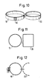
- FIG. 9 shows a pair of devices of containers 1, 2 with a plastic web 29 glued to the container bottom surfaces as a flexible swivel joint, the axis of rotation of which runs parallel to adjacent container walls;
- FIG. 10 shows an arrangement with two adjacent holding devices 10, 20 in the form of bands or half-shells for holding one container each, with a swivel joint again identified by dash-dotted lines and holding the holding devices together, in which the holding devices have a pivot point in common.
- Containers in particular (plastic) bottles, can be accommodated in the receiving devices 10, 20 in order to be able to be rotated relative to one another in the manner according to the invention without needing to be changed.
- the bands or half-shells (with bottom) 10, 20 can be wholly or partly, e.g. only in one section 30, be made of elastic material in order to be able to fit different container dimensions and shapes frictionally. Clamping or clamping devices can also be provided.
- FIG. 11 shows another arrangement with two adjacent holding devices 10, 20 in the form of bands or half-shells for holding one container each, with a swivel joint indicated by dash-dotted lines that holds the holding devices together, in which the holding devices have a rotary or swivel axis in common.
- Receiving devices 10, 20 of different cross-sectional shapes are possible; in addition to the circular and square cross-sectional shapes shown as examples, elliptical, polygonal and rounded further examples are elliptical, polygonal and rounded-polygonal cross-sectional shapes.
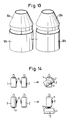
- FIG. 12 shows an arrangement corresponding to FIG. 10, the receiving device 10 being a band, the length of which can be adjusted in the manner of a hose clamp by means of a screw.
- Fig. 13 shows an arrangement of two pivotally connected receptacles in the form of divisible transfer containers 10a, 10b, 20a, 20b.
- containers 1, 2 can be inserted into the parts 10b and 20b, the shapes and dimensions of which do not have to be adapted to the shapes and dimensions of the containers , but can also be taken loose.
- the excess containers essentially leave only the openings of the containers received and otherwise hold the containers in their set relative position.
- the transfer containers are preferably made of an elastic, compressible material, so that they can be pressed together with the containers 1, 2 located therein in order to be able to expel their contents from the latter in an accelerated manner.
- FIG. 14 illustrates a further aspect of the concept according to the invention, namely adjacent containers 1, 2 with a releasable and reusable connecting element V, by means of which the containers 1, 2 can be held in a first adjacent arrangement, wherein the first adjacent arrangement can be detached and a second adjacent arrangement can be produced in which there is one or another angular distance between the openings.
- the connecting element V could in turn also releasably connect two receiving devices which each receive one of the containers or are capable of such receiving.
- the connecting element V can comprise, for example, a Velcro element, which is attached to a container 2, while one or two fabric surfaces are attached to the other container 1, into which the Velcro element can get caught in a selectable position.
- the connecting element V can comprise a magnetic element which is attached to a container 2, while one or two magnetizable surfaces are attached to the other container 1, to which the magnetic element can adhere in a selectable position.
- the connecting element V can comprise a clamping element in the manner of a flat toy clamping block which is attached to a container 2, while one or two complementary flat clamping elements are attached to the other container 1, with which the clamping element is clamped in at least two selectable positions can.
- the connecting element V can comprise an adhesive or adhesive element which is attached to a container 2, while the other container 1 has one or more smooth surfaces on which the adhesive element can be detachable and reusable in at least two selectable layers.
- the connecting element V can comprise a plug-in element which is attached to a container, while the other container has one or two complementary recesses into which the plug-in element can be inserted in at least two selectable positions without necessarily being rotatable.
- Devices according to Figures 1 to 9 and 14 or pairs of containers which are pivotally connected by means of an arrangement according to Figures 10 to 13 can be used, for example, in such a way that each container contains a different component of a mixture of substances to be produced, the container openings thanks to the swivel joint be brought into an angular distance and alternately the required component is brought out of the containers through their preferably nozzle-shaped openings, without the unused container needing to be parked and without the risk of leakage from the unused container and without the work hand would have to grip a shapeless or otherwise unergonomic device.
Landscapes
- Engineering & Computer Science (AREA)
- Mechanical Engineering (AREA)
- Details Of Rigid Or Semi-Rigid Containers (AREA)
Abstract
Claims (19)
- Dispositif comportant deux récipients (1,2), qui sont voisins l'un de l'autre, qui peuvent être saisis à la main et qui comportent chacun une ouverture, notamment des bouteilles en matière plastique, caractérisé par une articulation, grâce à laquelle les récipients (1,2) sont maintenus dans leur disposition réciproquement voisine et peuvent pivoter l'un par rapport à l'autre de telle sorte qu'un écart angulaire peut être établi entre les ouvertures.
- Dispositif suivant la revendication 1, caractérisé par le fait que l'articulation permet une rotation autour d'un axe de rotation sensiblement transversal à des parois voisines des récipients.
- Dispositif suivant la revendication 1, caractérisé par le fait que l'articulation permet une rotation autour d'un axe sensiblement parallèle à des parois voisines des récipients.
- Dispositif suivant l'une des revendications 1 à 3, caractérisé par le fait que l'articulation relie directement, avec possibilité de rotation, une paroi d'un récipient (1) à une paroi voisine de l'autre récipient (2).
- Dispositif suivant la revendication 4, caractérisé en ce que l'articulation comporte un corps axial, qui est raccordé aux deux parois voisines, notamment un corps axial vissable, qui peut tourner par rapport à au moins l'une des parois.
- Dispositif suivant la revendication 4, caractérisé par le fait que l'articulation est un système de liaison à enfichage, notamment à encliquetage brusque, dans lequel un élément de support (5;13;17) fixé sur ou dans une paroi d'un récipient (1), loge un corps enfichable (7;15;19) fixé sur la paroi voisine de l'autre récipient (2).
- Dispositif suivant la revendication 4, caractérisé par le fait que l'articulation est un système de liaison formant châssis notamment amovible, dans lequel deux corps creux (21,23) fixés respectivement aux parois voisines des récipients, logent un corps axial commun.
- Dispositif suivant la revendication 4, caractérisé par le fait que l'articulation est une liaison filetée, dans laquelle une douille filetée (9) fixée sur ou dans une paroi d'un récipient (1) loge une tige filetée (11) fixée sur la paroi voisine de l'autre récipient (2).
- Dispositif suivant la revendication 4, prise en référence à la revendication 3, caractérisé par le fait que l'articulation est constituée par une barrette en matériau flexible (27,29), notamment une barrette en matière plastique, qui est formée sur ou est fixée aux récipients (1,2), notamment respectivement à une surface de fond ou une arête d'un récipient, notamment par collage ou vissage, et franchit l'espace intercalaire présent entre les parois voisines.
- Dispositif suivant l'une des revendications 1 à 3, caractérisé par le fait que l'articulation relie entre eux, avec possibilité de rotation, deux dispositifs récepteurs (10,20), qui reçoivent chacun l'un des récipients (1,2).
- Dispositif suivant la revendication 10, caractérisé par le fait qu'au moins l'un des dispositifs récepteurs (10,20) enserre le récipient associé (1,2), sous la forme d'une bande dont la longueur est de préférence réglable.
- Dispositif suivant la revendication 10 ou 11, caractérisé par le fait qu'au moins l'un des dispositifs récepteurs (10,20) enserre sous la forme d'une demi-coque le récipient associé (1,2).
- Dispositif suivant l'une des revendications 10 à 12, caractérisé par le fait qu'au moins l'un des dispositifs récepteurs (10,20) enserre le récipient associé (1,2), sous la forme d'un récipient enveloppant (10a,10b, 20a,20b) , pouvant être subdivisé et qui, à l'état assemblé, libère sensiblement seulement l'ouverture du récipient (1,2).
- Dispositif suivant l'une des revendications 10 à 13, caractérisé par le fait que l'articulation est constituée par une barrette d'un matériau flexible (27,29), notamment une barrette en matière plastique, qui relie les dispositifs récepteurs (10,20).
- Dispositif comportant deux récipients (1,2), qui sont voisins l'un de l'autre, peuvent être saisis à la main et comportent chacun une ouverture, notamment des bouteilles en matière plastique, caractérisé par des éléments de liaison amovibles et réutilisables (V), grâce auxquels les récipients (1,2) peuvent être maintenus dans une première relation de voisinage, la première relation de voisinage pouvant être supprimée, tandis qu'à l'aide de ces éléments de liaison, il est possible d'établir une seconde relation de voisinage, dans laquelle il existe un écart angulaire ou un autre écart angulaire entre les ouvertures.
- Dispositif suivant la revendication 15, caractérisé par le fait que l'élément de liaison (V) relie entre eux de façon amovible deux dispositifs récepteurs, qui logent chacun l'un des récipients (1,2).
- Dispositif suivant la revendication 15 ou 16, caractérisé par le fait que l'élément de liaison (V) comprend un élément d'accrochage, un élément magnétique, un élément de serrage, un élément enfichable ou un élément adhésif.
- Dispositif suivant l'une des revendications 1 à 17, caractérisé par le fait que les récipients (1,2) contiennent chacun un constituant d'un mélange de substances devant être formé.
- Dispositif suivant l'une des revendications 1 à 18, caractérisé par le fait que l'ouverture d'au moins un récipient (1,2) se termine en forme de buse.
Applications Claiming Priority (2)
| Application Number | Priority Date | Filing Date | Title |
|---|---|---|---|
| DE8914557U | 1989-12-11 | ||
| DE8914557U DE8914557U1 (de) | 1989-12-11 | 1989-12-11 | Vorrichtung mit zwei benachbart angeordneten, von Hand greifbaren Behältern |
Publications (2)
| Publication Number | Publication Date |
|---|---|
| EP0457871A1 EP0457871A1 (fr) | 1991-11-27 |
| EP0457871B1 true EP0457871B1 (fr) | 1993-10-20 |
Family
ID=6845352
Family Applications (1)
| Application Number | Title | Priority Date | Filing Date |
|---|---|---|---|
| EP91900027A Expired - Lifetime EP0457871B1 (fr) | 1989-12-11 | 1990-12-10 | Dispositif avec deux recipients adjacents tenant dans la main |
Country Status (3)
| Country | Link |
|---|---|
| EP (1) | EP0457871B1 (fr) |
| DE (2) | DE8914557U1 (fr) |
| WO (1) | WO1991008963A1 (fr) |
Families Citing this family (8)
| Publication number | Priority date | Publication date | Assignee | Title |
|---|---|---|---|---|
| FR2671542A1 (fr) * | 1991-01-16 | 1992-07-17 | Resma Sarl | Reservoir en matiere plastique de contenance modulable. |
| DE9204755U1 (de) * | 1992-04-06 | 1992-06-25 | Schröder, Christoph, 8000 München | Tragbarer Behälter für fließ- und rieselfähige Stoffe, zugehörige Verbindungsvorrichtung zur Verbindung der Behälter und ein daraus gebildeter, portabler Mehrfachbehälter |
| FR2735104A1 (fr) * | 1995-06-09 | 1996-12-13 | Charpentier Georges | Dispositif de conditionnement de deux produits |
| WO1997013705A1 (fr) * | 1995-10-06 | 1997-04-17 | 'dropp ' Handels Gmbh | Recipient reutilisable |
| CA2345160A1 (fr) * | 2001-04-25 | 2002-10-25 | Roy Fenwick | Pot a fleurs polyvalent |
| DE102009026125A1 (de) * | 2009-07-07 | 2011-01-13 | Krones Ag | Getränkebehälter, Verbund mehrerer Getränkebehälter und Verfahren zum Herstellen der Getränkebehälter und des Verbundes |
| CN101633420B (zh) * | 2009-08-17 | 2011-04-20 | 湖北广彩印刷股份有限公司 | 一种旋转开启式双层包装盒 |
| DE102014002688A1 (de) * | 2014-02-28 | 2015-09-03 | Kautex Textron Gmbh & Co. Kg | Mehrkammerbehälter |
Family Cites Families (2)
| Publication number | Priority date | Publication date | Assignee | Title |
|---|---|---|---|---|
| US2166307A (en) * | 1938-10-19 | 1939-07-18 | Lewis L Libby | Connected collapsible twin tubes |
| DE1927534A1 (de) * | 1969-05-30 | 1971-03-11 | Enzinger Union Werke Ag | Transporteinheit aus Kunststoffflaschen |
-
1989
- 1989-12-11 DE DE8914557U patent/DE8914557U1/de not_active Expired - Lifetime
-
1990
- 1990-12-10 WO PCT/EP1990/002141 patent/WO1991008963A1/fr not_active Ceased
- 1990-12-10 DE DE91900027T patent/DE59003160D1/de not_active Expired - Fee Related
- 1990-12-10 EP EP91900027A patent/EP0457871B1/fr not_active Expired - Lifetime
Also Published As
| Publication number | Publication date |
|---|---|
| WO1991008963A1 (fr) | 1991-06-27 |
| DE59003160D1 (de) | 1993-11-25 |
| EP0457871A1 (fr) | 1991-11-27 |
| DE8914557U1 (de) | 1990-03-29 |
Similar Documents
| Publication | Publication Date | Title |
|---|---|---|
| DE2537022A1 (de) | Geraet zum messen, mischen und ausgeben von zwei komponenten aufweisenden materialien | |
| EP0457871B1 (fr) | Dispositif avec deux recipients adjacents tenant dans la main | |
| DE60106392T2 (de) | Abgabevorrichtung mit greifereinrichtung | |
| DE9107249U1 (de) | Parfümspender | |
| EP0276474A2 (fr) | Appareil de dosage | |
| DE69118524T2 (de) | Vorrichtung zum kontrollierten Ausgeben von Stoffen aus verformbaren Tuben | |
| EP1578539B1 (fr) | Dispositif distributeur pour substances fluides | |
| DE4237968A1 (de) | Trennwandelement zur Schubladeneinteilung von Schubladen | |
| EP0841098A2 (fr) | Dispositif de décharge d'une masse fluide | |
| DE4325390C2 (de) | Werkzeugkassette | |
| DE60200811T2 (de) | Elektrischer rotierender Rasierer | |
| EP0092718A1 (fr) | Sonde à ultrasons | |
| EP0920907A2 (fr) | Conteneur de mélange et de dosage | |
| DE3400897C2 (de) | Teigpresse | |
| EP0230955A2 (fr) | Dispositif applicateur avec organe d'application détachable | |
| DE9111109U1 (de) | Aufwickelvorrichtung für Binden oder Bandagen | |
| DE2427211A1 (de) | Spruehvorrichtung | |
| DE10132423C5 (de) | Baustein | |
| DE69002631T2 (de) | Auftragsgerät. | |
| DE9421475U1 (de) | Montagehilfe zum Verbinden von Teilen einer Schlauchverbindung | |
| EP4149864A2 (fr) | Utilisation d'un matériau allongé à flexibilité élastique ayant deux extrémités libres pour tendre un bord d'ouverture d'une ouverture d'un récipient souple, matériau allongé pour une telle utilisation et dispositif de retenue pour retenir le récipient souple avec le bord d'ouverture tendu par le matériau allongé | |
| DE3336274A1 (de) | Behaelterdeckel | |
| DE202022105023U1 (de) | Orientierungsmittel für einen dynamischen Mischer einer Mischapparatur und Kit | |
| DE112008003006B4 (de) | Klappbarer Flaschentransportbehälter | |
| EP0381821A1 (fr) | Dispositif destiné à contenir des articles à usage hygiénique |
Legal Events
| Date | Code | Title | Description |
|---|---|---|---|
| PUAI | Public reference made under article 153(3) epc to a published international application that has entered the european phase |
Free format text: ORIGINAL CODE: 0009012 |
|
| AK | Designated contracting states |
Kind code of ref document: A1 Designated state(s): DE FR GB IT |
|
| 17P | Request for examination filed |
Effective date: 19911223 |
|
| 17Q | First examination report despatched |
Effective date: 19920111 |
|
| GRAA | (expected) grant |
Free format text: ORIGINAL CODE: 0009210 |
|
| AK | Designated contracting states |
Kind code of ref document: B1 Designated state(s): DE FR GB IT |
|
| REF | Corresponds to: |
Ref document number: 59003160 Country of ref document: DE Date of ref document: 19931125 |
|
| GBT | Gb: translation of ep patent filed (gb section 77(6)(a)/1977) |
Effective date: 19931028 |
|
| ITF | It: translation for a ep patent filed | ||
| ET | Fr: translation filed | ||
| PLBE | No opposition filed within time limit |
Free format text: ORIGINAL CODE: 0009261 |
|
| STAA | Information on the status of an ep patent application or granted ep patent |
Free format text: STATUS: NO OPPOSITION FILED WITHIN TIME LIMIT |
|
| 26N | No opposition filed | ||
| PGFP | Annual fee paid to national office [announced via postgrant information from national office to epo] |
Ref country code: DE Payment date: 19990930 Year of fee payment: 9 |
|
| PGFP | Annual fee paid to national office [announced via postgrant information from national office to epo] |
Ref country code: FR Payment date: 19991230 Year of fee payment: 10 |
|
| PGFP | Annual fee paid to national office [announced via postgrant information from national office to epo] |
Ref country code: GB Payment date: 20000410 Year of fee payment: 10 |
|
| PG25 | Lapsed in a contracting state [announced via postgrant information from national office to epo] |
Ref country code: DE Free format text: LAPSE BECAUSE OF NON-PAYMENT OF DUE FEES Effective date: 20001003 |
|
| PG25 | Lapsed in a contracting state [announced via postgrant information from national office to epo] |
Ref country code: GB Free format text: LAPSE BECAUSE OF NON-PAYMENT OF DUE FEES Effective date: 20001210 |
|
| GBPC | Gb: european patent ceased through non-payment of renewal fee |
Effective date: 20001210 |
|
| PG25 | Lapsed in a contracting state [announced via postgrant information from national office to epo] |
Ref country code: FR Free format text: LAPSE BECAUSE OF NON-PAYMENT OF DUE FEES Effective date: 20010831 |
|
| REG | Reference to a national code |
Ref country code: FR Ref legal event code: ST |
|
| PG25 | Lapsed in a contracting state [announced via postgrant information from national office to epo] |
Ref country code: IT Free format text: LAPSE BECAUSE OF NON-PAYMENT OF DUE FEES;WARNING: LAPSES OF ITALIAN PATENTS WITH EFFECTIVE DATE BEFORE 2007 MAY HAVE OCCURRED AT ANY TIME BEFORE 2007. THE CORRECT EFFECTIVE DATE MAY BE DIFFERENT FROM THE ONE RECORDED. Effective date: 20051210 |