EP0457926B1 - Procédé et dispositif de fabrication de films tubulaires, de tuyaux ou de bandes en matière plastique - Google Patents
Procédé et dispositif de fabrication de films tubulaires, de tuyaux ou de bandes en matière plastique Download PDFInfo
- Publication number
- EP0457926B1 EP0457926B1 EP90101345A EP90101345A EP0457926B1 EP 0457926 B1 EP0457926 B1 EP 0457926B1 EP 90101345 A EP90101345 A EP 90101345A EP 90101345 A EP90101345 A EP 90101345A EP 0457926 B1 EP0457926 B1 EP 0457926B1
- Authority
- EP
- European Patent Office
- Prior art keywords
- air
- supporting air
- ring
- blowing head
- nozzle
- Prior art date
- Legal status (The legal status is an assumption and is not a legal conclusion. Google has not performed a legal analysis and makes no representation as to the accuracy of the status listed.)
- Expired - Lifetime
Links
- 238000000034 method Methods 0.000 title claims description 19
- 239000000463 material Substances 0.000 title claims description 18
- 238000004519 manufacturing process Methods 0.000 title claims description 7
- 239000004033 plastic Substances 0.000 title claims description 7
- 229920003023 plastic Polymers 0.000 title claims description 7
- 238000001816 cooling Methods 0.000 claims description 15
- 239000007788 liquid Substances 0.000 claims description 14
- 239000003381 stabilizer Substances 0.000 claims description 14
- 238000007664 blowing Methods 0.000 claims description 11
- XLYOFNOQVPJJNP-UHFFFAOYSA-N water Substances O XLYOFNOQVPJJNP-UHFFFAOYSA-N 0.000 claims description 9
- 239000002216 antistatic agent Substances 0.000 claims description 6
- 238000001125 extrusion Methods 0.000 claims description 6
- 238000004140 cleaning Methods 0.000 claims description 2
- 235000014113 dietary fatty acids Nutrition 0.000 claims description 2
- 239000000194 fatty acid Substances 0.000 claims description 2
- 229930195729 fatty acid Natural products 0.000 claims description 2
- -1 fatty acid esters Chemical class 0.000 claims description 2
- 239000003595 mist Substances 0.000 claims 3
- 229920000642 polymer Polymers 0.000 claims 3
- 239000007921 spray Substances 0.000 description 9
- 150000001875 compounds Chemical class 0.000 description 5
- 238000013461 design Methods 0.000 description 3
- 238000000605 extraction Methods 0.000 description 3
- 238000010438 heat treatment Methods 0.000 description 3
- 238000000465 moulding Methods 0.000 description 3
- 239000002245 particle Substances 0.000 description 3
- 239000000843 powder Substances 0.000 description 3
- 238000000889 atomisation Methods 0.000 description 2
- 238000010276 construction Methods 0.000 description 2
- 230000000694 effects Effects 0.000 description 2
- 239000002985 plastic film Substances 0.000 description 2
- 229920006255 plastic film Polymers 0.000 description 2
- GLGNXYJARSMNGJ-VKTIVEEGSA-N (1s,2s,3r,4r)-3-[[5-chloro-2-[(1-ethyl-6-methoxy-2-oxo-4,5-dihydro-3h-1-benzazepin-7-yl)amino]pyrimidin-4-yl]amino]bicyclo[2.2.1]hept-5-ene-2-carboxamide Chemical compound CCN1C(=O)CCCC2=C(OC)C(NC=3N=C(C(=CN=3)Cl)N[C@H]3[C@H]([C@@]4([H])C[C@@]3(C=C4)[H])C(N)=O)=CC=C21 GLGNXYJARSMNGJ-VKTIVEEGSA-N 0.000 description 1
- 230000001174 ascending effect Effects 0.000 description 1
- 238000004891 communication Methods 0.000 description 1
- 229940125758 compound 15 Drugs 0.000 description 1
- 238000013016 damping Methods 0.000 description 1
- 230000008021 deposition Effects 0.000 description 1
- 238000011161 development Methods 0.000 description 1
- 230000018109 developmental process Effects 0.000 description 1
- 238000009826 distribution Methods 0.000 description 1
- 239000000428 dust Substances 0.000 description 1
- 238000007786 electrostatic charging Methods 0.000 description 1
- 238000004880 explosion Methods 0.000 description 1
- 238000011049 filling Methods 0.000 description 1
- 238000010096 film blowing Methods 0.000 description 1
- 239000007789 gas Substances 0.000 description 1
- 238000002347 injection Methods 0.000 description 1
- 239000007924 injection Substances 0.000 description 1
- 238000009413 insulation Methods 0.000 description 1
- 238000011068 loading method Methods 0.000 description 1
- 230000007257 malfunction Effects 0.000 description 1
- 230000013011 mating Effects 0.000 description 1
- 238000010327 methods by industry Methods 0.000 description 1
- 230000000149 penetrating effect Effects 0.000 description 1
- 229920000098 polyolefin Polymers 0.000 description 1
- 238000004886 process control Methods 0.000 description 1
- 238000012545 processing Methods 0.000 description 1
- 238000007712 rapid solidification Methods 0.000 description 1
- 230000009257 reactivity Effects 0.000 description 1
- 238000007493 shaping process Methods 0.000 description 1
- 238000007711 solidification Methods 0.000 description 1
- 230000008023 solidification Effects 0.000 description 1
- 238000005507 spraying Methods 0.000 description 1
- 239000000126 substance Substances 0.000 description 1
- 238000011144 upstream manufacturing Methods 0.000 description 1
Images
Classifications
-
- B—PERFORMING OPERATIONS; TRANSPORTING
- B29—WORKING OF PLASTICS; WORKING OF SUBSTANCES IN A PLASTIC STATE IN GENERAL
- B29C—SHAPING OR JOINING OF PLASTICS; SHAPING OF MATERIAL IN A PLASTIC STATE, NOT OTHERWISE PROVIDED FOR; AFTER-TREATMENT OF THE SHAPED PRODUCTS, e.g. REPAIRING
- B29C37/00—Component parts, details, accessories or auxiliary operations, not covered by group B29C33/00 or B29C35/00
- B29C37/0067—Using separating agents during or after moulding; Applying separating agents on preforms or articles, e.g. to prevent sticking to each other
-
- B—PERFORMING OPERATIONS; TRANSPORTING
- B29—WORKING OF PLASTICS; WORKING OF SUBSTANCES IN A PLASTIC STATE IN GENERAL
- B29C—SHAPING OR JOINING OF PLASTICS; SHAPING OF MATERIAL IN A PLASTIC STATE, NOT OTHERWISE PROVIDED FOR; AFTER-TREATMENT OF THE SHAPED PRODUCTS, e.g. REPAIRING
- B29C48/00—Extrusion moulding, i.e. expressing the moulding material through a die or nozzle which imparts the desired form; Apparatus therefor
- B29C48/03—Extrusion moulding, i.e. expressing the moulding material through a die or nozzle which imparts the desired form; Apparatus therefor characterised by the shape of the extruded material at extrusion
- B29C48/09—Articles with cross-sections having partially or fully enclosed cavities, e.g. pipes or channels
-
- B—PERFORMING OPERATIONS; TRANSPORTING
- B29—WORKING OF PLASTICS; WORKING OF SUBSTANCES IN A PLASTIC STATE IN GENERAL
- B29C—SHAPING OR JOINING OF PLASTICS; SHAPING OF MATERIAL IN A PLASTIC STATE, NOT OTHERWISE PROVIDED FOR; AFTER-TREATMENT OF THE SHAPED PRODUCTS, e.g. REPAIRING
- B29C48/00—Extrusion moulding, i.e. expressing the moulding material through a die or nozzle which imparts the desired form; Apparatus therefor
- B29C48/03—Extrusion moulding, i.e. expressing the moulding material through a die or nozzle which imparts the desired form; Apparatus therefor characterised by the shape of the extruded material at extrusion
- B29C48/09—Articles with cross-sections having partially or fully enclosed cavities, e.g. pipes or channels
- B29C48/10—Articles with cross-sections having partially or fully enclosed cavities, e.g. pipes or channels flexible, e.g. blown foils
-
- B—PERFORMING OPERATIONS; TRANSPORTING
- B29—WORKING OF PLASTICS; WORKING OF SUBSTANCES IN A PLASTIC STATE IN GENERAL
- B29C—SHAPING OR JOINING OF PLASTICS; SHAPING OF MATERIAL IN A PLASTIC STATE, NOT OTHERWISE PROVIDED FOR; AFTER-TREATMENT OF THE SHAPED PRODUCTS, e.g. REPAIRING
- B29C48/00—Extrusion moulding, i.e. expressing the moulding material through a die or nozzle which imparts the desired form; Apparatus therefor
- B29C48/25—Component parts, details or accessories; Auxiliary operations
- B29C48/88—Thermal treatment of the stream of extruded material, e.g. cooling
- B29C48/885—External treatment, e.g. by using air rings for cooling tubular films
-
- B—PERFORMING OPERATIONS; TRANSPORTING
- B29—WORKING OF PLASTICS; WORKING OF SUBSTANCES IN A PLASTIC STATE IN GENERAL
- B29C—SHAPING OR JOINING OF PLASTICS; SHAPING OF MATERIAL IN A PLASTIC STATE, NOT OTHERWISE PROVIDED FOR; AFTER-TREATMENT OF THE SHAPED PRODUCTS, e.g. REPAIRING
- B29C48/00—Extrusion moulding, i.e. expressing the moulding material through a die or nozzle which imparts the desired form; Apparatus therefor
- B29C48/25—Component parts, details or accessories; Auxiliary operations
- B29C48/88—Thermal treatment of the stream of extruded material, e.g. cooling
- B29C48/89—Internal treatment, e.g. by applying an internal cooling fluid stream
-
- B—PERFORMING OPERATIONS; TRANSPORTING
- B29—WORKING OF PLASTICS; WORKING OF SUBSTANCES IN A PLASTIC STATE IN GENERAL
- B29C—SHAPING OR JOINING OF PLASTICS; SHAPING OF MATERIAL IN A PLASTIC STATE, NOT OTHERWISE PROVIDED FOR; AFTER-TREATMENT OF THE SHAPED PRODUCTS, e.g. REPAIRING
- B29C48/00—Extrusion moulding, i.e. expressing the moulding material through a die or nozzle which imparts the desired form; Apparatus therefor
- B29C48/25—Component parts, details or accessories; Auxiliary operations
- B29C48/88—Thermal treatment of the stream of extruded material, e.g. cooling
- B29C48/911—Cooling
- B29C48/9115—Cooling of hollow articles
- B29C48/912—Cooling of hollow articles of tubular films
Definitions
- the invention relates to methods according to the preamble of claim 1 and claim 2 and to a device according to the preamble of claim 4.
- electrostatic charges can occur due to the material, e.g. on injection molded parts and films made of polyolefins. On the charged surfaces, these can then attract each other or attract foreign substances such as dust, fluff, pieces of paper and the like. stick. Discharges that occur often involve a high risk of explosion. Even if film materials with so-called internal antistatic equipment are already being used, there are risks above all when handling dusts, powdery material, etc. in connection with plastic films, for example when filling them into suitable bags and sacks.
- a hose blowing method is known from US Pat. No. 2,668,323 in which a continuous exchange of air within the resulting hose is intended to ensure that it sticks together its inner surfaces between the take-off rollers is prevented.
- the supply of compressed air, possibly with a moisture load, and suction of the gas volume in the blow hose are provided.
- this also involves the uncontrolled removal of the liquid content, so that no constant antistatic surface properties can occur.
- the desired antistatic properties of the plastic product are achieved by metered supply of water at the moment of shaping, by adding water together with supporting air through an extrusion head is fed through, preferably concentrically to an annular nozzle, wherein the antistatic on the surface (s) combines with the finely divided water supplied.
- this method with continuous support air extraction does not allow the aforementioned internal air exchange in the blow hose to be used in such a way that an adequate liquid concentration is maintained. Rather, there is conventionally an uneven removal of water particles due to the turbulent air exchange, which is in itself desirable for the rapid solidification and stable antistatic treatment of the hose or tube produced.
- US-A-3 750 948 (Saito) describes a device for the metered-uniform deposition of a fine powder on the inner surface of a blow hose by means of electrostatic charging.
- a spray head At the end of a delivery line there is a spray head in the form of an insulating ring with an electrode which is supplied with at least 30 kV via a high-voltage cable.
- the delivery line and cable penetrate the mandrel of the blow head at an angle to its axis with suitable insulation.
- the air supply channel in the core of the blow head passes through a feed line which has at least one distributor opening at the upper end and can be heated in order to atomize it Evaporate material.
- a feed line which has at least one distributor opening at the upper end and can be heated in order to atomize it Evaporate material.
- An indoor air exchange is missing; one embodiment has a liquid bath in the interior of a downwardly directed hose part.
- the invention aims to improve and accelerate the production of plastic hoses, tubes and webs with antistatic equipment in an economical manner.
- An important aim of the invention is to create and design methods and means which, using the film blowing method, deliver a product quality which is better than the prior art and at the same time a considerable increase in performance.
- the antistatic treatment is carried out in that the liquid to be atomized contains antistatic agents which accumulate on the inner surface of the blow hose and firmly connect to it.
- antistatic agents which accumulate on the inner surface of the blow hose and firmly connect to it.
- hydrophilic antistatic agents such as fatty acid esters are added to the material to be molded, which are activated by the mere addition of fine water particles from the atomizing air.
- the amount of liquid required for the antistatic equipment is atomized in a controlled manner above the blow head according to the invention, while inside air exchange takes place in the blow hose with continuous partial air removal. In this way, a significant increase in both profitability and production quality is achieved with extremely little effort. While conventionally the production of plastic films with antistatic equipment was only possible on extruders without internal air exchange, thanks to the atomization according to the invention at a predetermined distance above the blow head, the desired antistatic equipment can also be effectively installed in the upper part of the continuously produced blow hose with the thermodynamically advantageous internal air exchange.
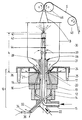
- the invention provides, according to the characterizing part of claim 4, that the inner nozzle, which is designed as a spray head and is arranged at a predetermined distance above the ring nozzle, is located at the upper end of a support tube which penetrates the blow head centrally and that the inner nozzle penetrating the blow head is fed by separate lines which run inside an air extraction duct, which in turn is surrounded by the supporting air supply pipe. So you have a line or pipe string that passes through the blow head, particularly centrally. The molding compound is extruded upwards through the inner nozzle.
- the construction is structurally very simple and clear, therefore also easy to maintain.
- the support tube holds or forms a flow stabilizer at or near the ring nozzle.
- the swirling in the lower part of the blow hose, which occurs when the supporting air flows in, is thus damped without impairing the cooling effect on the inside surfaces of the film.
- the flow stabilizer or the like from outlet openings, nozzles. be formed on or in the support tube. It is also possible and contemplated according to the invention to provide damping surfaces of suitable design on the support tube, for example in the form of flat or sinuous wing blades, ribs or the like.
- a flow box is present as a flow stabilizer or in addition to this, which concentrically surrounds the support tube in the axial region of the cooling ring.
- claim 5 For suction during the exchange of internal air, claim 5 provides an air suction ring or connector between the inner nozzle and the flow stabilizer, so that the hot product heated air is sucked off relatively close to the material ring nozzle and in any case in the lower part of the blow hose, which contributes significantly to rapid cooling and consequently to the solidification of the hose material.
- a blow head designated overall with 10 has a heating and pressure ring 12 and a blow head intermediate ring 13 and inside a distributor coil 14 with screw connection 15.
- the latter feeds an annular feed channel 16 for extrusion compound, which is between a nozzle plate 17 and a mandrel 18 arranged concentrically therein is available.
- the feed channel 16 tapers upwards and opens into an annular nozzle 20, namely in the form of a nozzle gap, from which the preheated molding compound emerges under pressure.
- An attached cooling ring 24 can be fastened with (not shown) anchor screws, which hold it together with a counter ring 26 with the entire blow head 10.
- An outside air connection 25 is provided between the cooling ring 24 and the counter ring 26, by means of which cooling air is fed radially to the nozzle gap or the ring nozzle 20.
- a supporting air pipe socket 22 leads centrally through the blow head 10 from the screw connection 15.
- a support tube 30 is arranged in the interior of the supporting air tube 22 and extends far beyond the ring nozzle 20 and the cooling ring 24 protrudes upwards.
- the support tube 30 is provided with a flow stabilizer 28, for example in the form of outlet openings 29, nozzles or the like.
- a perforated box 31 can be mounted concentrically in this area, which is fastened to a shoulder body 27 which projects into the upper end of the supporting air tube 22 in the mandrel 18.
- an internal air suction connection 32 into which a water supply line 34 and an atomizing air supply line 36 go.
- the two lines 34, 36 pass through the full length of the support tube 30, which ends in a spray head 40.
- Two holding plates 42, 44 are used to fasten the spray head 40 and as a shielding plate above a suction ring 38, which is arranged between the spray head 40 and the flow stabilizer 28 or the perforated box 31 and is in flow communication with the interior of the support tube 30.
- molding compound 15 is pressed into the distributor coil 14 of the heating and pressure ring 12 via the screw connection 15 and further into the feed channel 16, from which the compound is extruded through the ring nozzle 20.
- support air 22 supplied internally via the pipe 22 passes the attachment body 27 and the flow stabilizer 28 or the perforated box 31 and cools the resulting blow hose B in its lower part.
- cooling air is also supplied between the cooling ring 24 and the counter ring 26 through the connection 25, which air flows along the outside of the blow hose B.
- blow hose B As the blow hose B rises and solidifies, liquid is atomized from the spray head 40 through the feed lines 34, 36. It is reflected in the upper part of the blow hose interior and thereby effects the antistatic treatment of the material already solidified here just as quickly and permanently.
- the blow hose B is brought together on take-off rollers 46 and drawn off via a deflecting roller 48 in the form of a tubular web S and then wound.
- the spray head 40 is arranged at a height h above the ring nozzle 20 and therefore relatively far away from it. This distance h results from the control parameters, which include the film thickness, extrusion pressure and temperature, air pressure in the blown tube B and withdrawal speed of the tube sheet S.
- the product quality and the take-off speed are significantly influenced by the fact that internal air is continuously sucked out relatively close to the stabilizer 28 via the suction ring 38 and is conveyed to the outside via the nozzle 32.
- blow hose B solidifies very quickly ascending; he receives his antistatic equipment in the upper section in front of the take-off rollers 46, where the merged tubular web S can already be removed continuously without the risk of electrostatic sticking of the inner surfaces.
- the inner air stabilizer 28 dampens the swirling that occurs when the supporting air flows in.
- the given flow resistance is moderate, so that the cooling air can spread well.
- the stabilizer 28 is designed as a flow guide body in order on the one hand to bring the supplied supporting air as quickly as possible to the lower end of the interior of the blow hose and on the other hand to rapidly remove a large part of the largely dry internal air via the suction ring 38 ensure.
Landscapes
- Engineering & Computer Science (AREA)
- Mechanical Engineering (AREA)
- Physics & Mathematics (AREA)
- Thermal Sciences (AREA)
- Extrusion Moulding Of Plastics Or The Like (AREA)
Claims (8)
- Procédé de fabrication de films tubulaires, de tuyaux ou de bandes en matière plastique, particulièrement de polymères, où le matériau est extrudé d'une tête de soufflage comme gaine soufflée, pendant que de l'air de soutien et un liquide finement reparti sont introduits à l'intérieur de la gaine, notamment sous forme de brouillard ou de vapeur, et que de l'air de soutien est retiré, caractérisé par le fait que liquide contient des agents antistatiques et qu'il est pulvérisé avec un dosage commandé à une distance donnée au-dessus de la tête de soufflage, pendant qu'un échange de l'air intérieur a lieu dans le secteur d'arrivée de l'air de soutien de la gaine soufflée, avec une évacuation partielle et continue de l'air.
- Procédé de fabrication de films tubulaires, de tuyaux ou de bandes en matière plastique, particulièrement de polymères, où l'on ajoute au matériau devant être formé des agents antistatiques hydrophiles tels que l'ester d'acide gras, à la suite de quoi il est extrudé d'une tête de soufflage, et où du brouillard et/ou de la vapeur sont introduits avec de l'air de soutien à un tel dosage pendant l'extrusion à l'intérieur de la gaine soufflée, que l'eau introduite et finement repartie peut être absorbée entièrement par les agents antistatiques présents sur le côté intérieur de la gaine soufflée, pendant que l'air de soutien est retiré, caractérisé par le fait que la quantité d'eau nécessitée est pulvérisée de façon contrôlée à une distance donnée au-dessus de la tête de soufflage, alors qu'un échange de l'air intérieur a lieu dans le secteur d'arrivée de l'air de soutien de la gaine soufflée, avec une évacuation partielle et continue de l'air.
- Procédé conforme à la revendication 1 ou 2, caractérisé par le fait que l'évacuation partielle de l'air de l'intérieur de la gaine soufflée est effectuée à contre-courant de l'arrivée de l'air de soutien et du liquide devant être pulvérisé.
- Dispositif de fabrication de films tubulaires ou de tuyaux en matière plastique, particulièrement de polymères, avec une tête de soufflage (10) pour extruder le matériau devant être déformé à travers une filière annulaire (20), à laquelle est assujetti un anneau de refroidissement (24) l'enveloppant à l'extérieur, avec une filière intérieure (40) traversant la tête de soufflage (10) pour une alimentation dosée en air de soutien et en brouillard et/ou en vapeur pendant l'extrusion, et avec un canal d'aspiration de l'air (30, 32), qui est entouré dans le secteur de la tête de soufflage (10) d'un tuyau d'alimentation en air de soutien (22), et par qui de l'air de soutien est retiré, particulièrement pour réaliser le procédé d'après l'une des revendications 1 à 3, caractérisé par le fait que la filière intérieure (40) en forme de tête de pulvérisation disposée à une distance donnée (h) au-dessus de la filière annulaire (20) est située à l'extrémité supérieure d'un tuyau porteur (30) traversant la tête de soufflage (10) au centre et qu'elle est alimentée par des conduites séparées (34, 36) qui passent à l'intérieur du canal d'aspiration de l'air (30, 32).
- Dispositif conforme à la revendication 4, caractérisé par le fait qu'un anneau ou manchon d'aspiration de l'air (38) est disposé sur le tuyau porteur (30) entre la filière intérieure (40) et un stabilisateur de courant (28).
- Dispositif conforme à la revendication 4 ou 5, caractérisé par le fait que dans le secteur de la filière annulaire (20), le tuyau porteur (30) supporte ou forme un stabilisateur de courant (28), qui a notamment des ouvertures de sortie (29), des filières, etc. sur ou dans le tuyau porteur (30).
- Dispositif conforme à la revendication 5 ou 6, caractérisé par le fait qu'il y a comme stabilisateur de courant (28) ou complémentairement à celui-ci une boîte perforée, qui entoure concentriquement le tuyau porteur (30) dans le secteur axial de l'anneau de refroidissement (24).
- Dispositif conforme à l'une de revendications 4 à 7, caractérisé par le fait que des filtres de nettoyage et/ou des régulateurs de pression sont placés avant les conduites d'alimentation (34, 36) du pulvérisateur.
Priority Applications (2)
| Application Number | Priority Date | Filing Date | Title |
|---|---|---|---|
| EP90101345A EP0457926B1 (fr) | 1990-01-24 | 1990-01-24 | Procédé et dispositif de fabrication de films tubulaires, de tuyaux ou de bandes en matière plastique |
| DE9090101345T DE59000469D1 (de) | 1990-01-24 | 1990-01-24 | Verfahren und vorrichtung zum herstellen von kunststoff-schlaeuchen, -rohren oder-bahnen. |
Applications Claiming Priority (1)
| Application Number | Priority Date | Filing Date | Title |
|---|---|---|---|
| EP90101345A EP0457926B1 (fr) | 1990-01-24 | 1990-01-24 | Procédé et dispositif de fabrication de films tubulaires, de tuyaux ou de bandes en matière plastique |
Publications (2)
| Publication Number | Publication Date |
|---|---|
| EP0457926A1 EP0457926A1 (fr) | 1991-11-27 |
| EP0457926B1 true EP0457926B1 (fr) | 1992-11-11 |
Family
ID=8203531
Family Applications (1)
| Application Number | Title | Priority Date | Filing Date |
|---|---|---|---|
| EP90101345A Expired - Lifetime EP0457926B1 (fr) | 1990-01-24 | 1990-01-24 | Procédé et dispositif de fabrication de films tubulaires, de tuyaux ou de bandes en matière plastique |
Country Status (2)
| Country | Link |
|---|---|
| EP (1) | EP0457926B1 (fr) |
| DE (1) | DE59000469D1 (fr) |
Families Citing this family (2)
| Publication number | Priority date | Publication date | Assignee | Title |
|---|---|---|---|---|
| IT1306664B1 (it) * | 1999-05-25 | 2001-10-02 | Bp Europack Spa | Procedimento per la realizzazione di un film in materia plastica concaratteristiche migliorate, attrezzatura per realizzare il |
| DE102006007482B4 (de) | 2006-02-17 | 2014-06-18 | Leadx Ag | Vorrichtung und Verfahren zur Herstellung einer rohrförmigen Umhüllung |
Family Cites Families (10)
| Publication number | Priority date | Publication date | Assignee | Title |
|---|---|---|---|---|
| US2668323A (en) * | 1951-12-12 | 1954-02-09 | Louis Danenberg | Means for treating the interior surface of tubing being extruded |
| US3065097A (en) * | 1960-01-20 | 1962-11-20 | Dow Chemical Co | Method of dusting flexible film tubing internally |
| US3709642A (en) * | 1970-12-02 | 1973-01-09 | F Stannard | Tube coating film and apparatus |
| US4011128A (en) * | 1971-09-09 | 1977-03-08 | Nippon Ekika Seikei Kabushiki Kaisha | Apparatus for forming a cross-oriented film |
| US3750948A (en) * | 1971-11-09 | 1973-08-07 | Nikka Kk | Apparatus for depositing powdered substance on the inner surface of inflation tube |
| DE2639551C2 (de) * | 1976-09-02 | 1982-04-08 | Reifenhäuser KG, 5210 Troisdorf | Vorrichtung zum Blasen von Schlauchfolien aus thermoplastischem Kunststoff |
| DE3003620C2 (de) * | 1980-02-01 | 1985-10-10 | Polysackfabrik Walter Dürbeck GmbH und Co, 6420 Lauterbach | Verfahren zum Herstellen von Schläuchen oder Rohren aus Kunststoff |
| NZ200767A (en) * | 1981-07-31 | 1986-04-11 | Grace W R & Co | Tubular oriented plastics film blown bubble process:polyorganosiloxane coating on tube interior |
| DE3429963A1 (de) * | 1984-08-16 | 1986-02-27 | Wolff Walsrode Ag, 3030 Walsrode | Innenbestaeubung von folienschlaeuchen aus thermoplasten |
| JPH0249036A (ja) * | 1988-04-08 | 1990-02-19 | Asahi Chem Ind Co Ltd | ダステイング処理剤並びにダステイング処理した熱可塑性樹脂フイルム及びそのフイルムのダステイング処理方法 |
-
1990
- 1990-01-24 DE DE9090101345T patent/DE59000469D1/de not_active Expired - Lifetime
- 1990-01-24 EP EP90101345A patent/EP0457926B1/fr not_active Expired - Lifetime
Also Published As
| Publication number | Publication date |
|---|---|
| EP0457926A1 (fr) | 1991-11-27 |
| DE59000469D1 (de) | 1992-12-17 |
Similar Documents
| Publication | Publication Date | Title |
|---|---|---|
| DE68923931T2 (de) | Formtrennsysteme. | |
| DE2517964C2 (de) | Vorrichtung zum kontinuierlichen Vulkanisieren einer endlosen Länge aus vulkanisierbarem Elastomerenmaterial | |
| EP3083176B1 (fr) | Injecteur servant à remplir un moule de particules de matière plastique | |
| DE19519092A1 (de) | Pneumatisch beschicktes Pulverzuführungssystem sowie Vorrichtung zur Pulverbeschichtung | |
| DD249412A5 (de) | Verfahren und vorrichtung zum trocken eines fluessigen materials | |
| EP0076472A1 (fr) | Dispositif pour la distribution uniforme d'un courant d'une matière en vrac | |
| WO2015092008A1 (fr) | Dispositif et procédé de fusion en zone flottante d'un matériau et d'atomisation du matériau fondu pour fabriquer de la poudre | |
| DE2908723A1 (de) | Verfahren und vorrichtung zum elektrostatischen spruehen einer fluessigkeit | |
| DE19621072A1 (de) | Elektrostatische Sprühvorrichtung | |
| DE2541927A1 (de) | Pulverzerstaeuberduese mit strahlverstellung | |
| DE1230695B (de) | Verfahren und Vorrichtung zum elektro-statischen Bespruehen eines Werkstuecks mit fluessigem UEberzugsmaterial | |
| DE202016106243U1 (de) | Vorrichtung zur Herstellung von pulverförmigen Kunststoffen mit möglichst kugelförmiger Struktur | |
| EP0777534B1 (fr) | Dispositif de mise en peinture de pieces par pulverisation | |
| DE2018814A1 (de) | Verfahren und Vorrichtung zur Herstellung von rohrförmigen Hohlkörpern aus einlageverstärktem Kunstharz im Schleuderverfahren | |
| DE69101234T2 (de) | Pultrudierte profile. | |
| DE1629798A1 (de) | Verfahren und Vorrichtung zum Kuehlen von thermoplastischen Folien | |
| EP0457926A1 (fr) | Procédé et dispositif de fabrication de films tubulaires, de tuyaux ou de bandes en matière plastique | |
| DE1435571A1 (de) | Einrichtung und Verfahren zum Spinnen eines aus endlosen Faeden bestehenden Garnes | |
| DE3329880A1 (de) | Verfahren zum spritzbeschichten ohne luft und spritzpistole fuer das beschichten ohne luft | |
| DE3007990C2 (fr) | ||
| DE3546231A1 (de) | Pulver-spruehpistole | |
| EP0455106B1 (fr) | Procédé et installation pour revêtir en série des pièces d'oeuvre d'un matériau de revêtement conducteur | |
| DE69402762T2 (de) | Pneumatischer Flachstrahlzerstauber zum Versprühen von Beschichtungsmaterialien | |
| DE19753660A1 (de) | Verfahren zum Auftragen von pulverförmigen Trennmitteln in Spritzgußmaschinen | |
| DE1577757C3 (fr) |
Legal Events
| Date | Code | Title | Description |
|---|---|---|---|
| PUAI | Public reference made under article 153(3) epc to a published international application that has entered the european phase |
Free format text: ORIGINAL CODE: 0009012 |
|
| 17P | Request for examination filed |
Effective date: 19901206 |
|
| AK | Designated contracting states |
Kind code of ref document: A1 Designated state(s): AT BE CH DE ES FR GB GR IT LI LU NL SE |
|
| GRAA | (expected) grant |
Free format text: ORIGINAL CODE: 0009210 |
|
| AK | Designated contracting states |
Kind code of ref document: B1 Designated state(s): BE DE FR GB LU NL |
|
| PG25 | Lapsed in a contracting state [announced via postgrant information from national office to epo] |
Ref country code: NL Effective date: 19921111 Ref country code: GB Effective date: 19921111 |
|
| REF | Corresponds to: |
Ref document number: 59000469 Country of ref document: DE Date of ref document: 19921217 |
|
| ET | Fr: translation filed | ||
| PG25 | Lapsed in a contracting state [announced via postgrant information from national office to epo] |
Ref country code: BE Effective date: 19930131 Ref country code: LU Free format text: LAPSE BECAUSE OF NON-PAYMENT OF DUE FEES Effective date: 19930131 |
|
| NLV1 | Nl: lapsed or annulled due to failure to fulfill the requirements of art. 29p and 29m of the patents act | ||
| GBV | Gb: ep patent (uk) treated as always having been void in accordance with gb section 77(7)/1977 [no translation filed] |
Effective date: 19921111 |
|
| BERE | Be: lapsed |
Owner name: DURBECK G.M.B.H. & CO. K.G. Effective date: 19930131 |
|
| PLBE | No opposition filed within time limit |
Free format text: ORIGINAL CODE: 0009261 |
|
| STAA | Information on the status of an ep patent application or granted ep patent |
Free format text: STATUS: NO OPPOSITION FILED WITHIN TIME LIMIT |
|
| PG25 | Lapsed in a contracting state [announced via postgrant information from national office to epo] |
Ref country code: FR Effective date: 19930930 |
|
| 26N | No opposition filed | ||
| REG | Reference to a national code |
Ref country code: FR Ref legal event code: ST |
|
| PGFP | Annual fee paid to national office [announced via postgrant information from national office to epo] |
Ref country code: DE Payment date: 20080121 Year of fee payment: 19 |
|
| PG25 | Lapsed in a contracting state [announced via postgrant information from national office to epo] |
Ref country code: DE Free format text: LAPSE BECAUSE OF NON-PAYMENT OF DUE FEES Effective date: 20090801 |