EP0457941B1 - Gerät und Verfahren zur Temperaturmessung durch Verwendung optischer Fasern - Google Patents
Gerät und Verfahren zur Temperaturmessung durch Verwendung optischer Fasern Download PDFInfo
- Publication number
- EP0457941B1 EP0457941B1 EP90109704A EP90109704A EP0457941B1 EP 0457941 B1 EP0457941 B1 EP 0457941B1 EP 90109704 A EP90109704 A EP 90109704A EP 90109704 A EP90109704 A EP 90109704A EP 0457941 B1 EP0457941 B1 EP 0457941B1
- Authority
- EP
- European Patent Office
- Prior art keywords
- optical fiber
- scattered light
- temperature
- raman scattered
- measurement
- Prior art date
- Legal status (The legal status is an assumption and is not a legal conclusion. Google has not performed a legal analysis and makes no representation as to the accuracy of the status listed.)
- Expired - Lifetime
Links
- 239000013307 optical fiber Substances 0.000 title claims description 62
- 238000000034 method Methods 0.000 title claims description 21
- 238000005259 measurement Methods 0.000 claims description 58
- 238000001069 Raman spectroscopy Methods 0.000 claims description 40
- 238000009529 body temperature measurement Methods 0.000 claims description 10
- 230000003287 optical effect Effects 0.000 claims description 10
- 230000004044 response Effects 0.000 claims description 2
- 238000005070 sampling Methods 0.000 claims description 2
- 230000002093 peripheral effect Effects 0.000 claims 2
- 230000002401 inhibitory effect Effects 0.000 claims 1
- 239000000835 fiber Substances 0.000 description 8
- 238000000253 optical time-domain reflectometry Methods 0.000 description 8
- 238000012545 processing Methods 0.000 description 7
- 239000000126 substance Substances 0.000 description 5
- 238000012935 Averaging Methods 0.000 description 3
- 238000001816 cooling Methods 0.000 description 3
- 239000013078 crystal Substances 0.000 description 2
- 239000000284 extract Substances 0.000 description 2
- 230000005855 radiation Effects 0.000 description 2
- 230000035945 sensitivity Effects 0.000 description 2
- 238000001237 Raman spectrum Methods 0.000 description 1
- 238000004364 calculation method Methods 0.000 description 1
- 238000006243 chemical reaction Methods 0.000 description 1
- 239000011162 core material Substances 0.000 description 1
- 230000003247 decreasing effect Effects 0.000 description 1
- 238000001514 detection method Methods 0.000 description 1
- 238000010586 diagram Methods 0.000 description 1
- 230000000694 effects Effects 0.000 description 1
- 230000005284 excitation Effects 0.000 description 1
- 230000006870 function Effects 0.000 description 1
- 239000012535 impurity Substances 0.000 description 1
- 238000004519 manufacturing process Methods 0.000 description 1
- 238000013507 mapping Methods 0.000 description 1
- 238000000691 measurement method Methods 0.000 description 1
- 238000012544 monitoring process Methods 0.000 description 1
- 238000002168 optical frequency-domain reflectometry Methods 0.000 description 1
- 238000002310 reflectometry Methods 0.000 description 1
- 230000002269 spontaneous effect Effects 0.000 description 1
Images



Classifications
-
- G—PHYSICS
- G01—MEASURING; TESTING
- G01K—MEASURING TEMPERATURE; MEASURING QUANTITY OF HEAT; THERMALLY-SENSITIVE ELEMENTS NOT OTHERWISE PROVIDED FOR
- G01K11/00—Measuring temperature based upon physical or chemical changes not covered by groups G01K3/00, G01K5/00, G01K7/00 or G01K9/00
- G01K11/32—Measuring temperature based upon physical or chemical changes not covered by groups G01K3/00, G01K5/00, G01K7/00 or G01K9/00 using changes in transmittance, scattering or luminescence in optical fibres
-
- G—PHYSICS
- G01—MEASURING; TESTING
- G01K—MEASURING TEMPERATURE; MEASURING QUANTITY OF HEAT; THERMALLY-SENSITIVE ELEMENTS NOT OTHERWISE PROVIDED FOR
- G01K1/00—Details of thermometers not specially adapted for particular types of thermometer
- G01K1/02—Means for indicating or recording specially adapted for thermometers
- G01K1/026—Means for indicating or recording specially adapted for thermometers arrangements for monitoring a plurality of temperatures, e.g. by multiplexing
Definitions
- the present invention relates to a measuring apparatus and method for measuring the temperature, humidity, temperature distribution, or the like in a measurement region by radiating an optical signal onto the incidence end of an optical fiber arranged in the measurement region and analyzing backscattered light.
- thermometer A technique of using an optical fiber as a thermometer is disclosed, for example, in "New fiber optic distributed temperature sensor", SPIE Vol. 798 Fiber Optic Sensors II (1987) pp. 131 to 136, or in UK Patent Application GB 2140554A. The disclosures of these references are incorporated in the specification.
- thermometer In such a thermometer, backscattered light from each point of an optical fiber is weak, and noise is mixed in this weak optical signal.
- optical fibers slightly differ in characteristics from each other. For these reasons, it is very difficult to discriminate temperature measurement positions of an optical fiber and to accurately measure temperatures at the respective positions.
- OFDR Optical Frequency Domain Reflectometory
- Prior art document US-A-4 859 065 discloses a method of measuring temperature which comprises the steps of consecutively launching input pulses of light at two different wavelengths into a temperature sensing element in the form of an elongate optical fiber, passing Roman scattered light from said element and deriving from said input pulses to intensity detectors, obtaining from the detectors output signals indicative of the intensity of the Raman scattered light; and processing said output signals to provide a temperature measurement.
- a known position along the optical fiber is maintained at a known temperature to provide a reference for deriving temperature measurements at other positions along the optical fiber.
- prior art document "Proceedings of the SPIE, vol. 1172, 1989, pages 194 to 205 discloses application of fiber-optic distributed temperature sensing to process monitoring and control environment.
- the measurement technique utilizes a modified optical time-domain reflectometer arrangement, where an excitation pulse is launched into the fiber, and a temperature-sensitive property of the backscatter is analyzed as a function of time. From this information the temperature profile along the length of the fiber is deduced.
- the fiber itself is used as the sensor, and the temperature-sensitive property measured is the spontaneous anti-Stokes Raman scattering of the fiber core material.
- the fiber is arranged in form of a coil at the respective measurement points, and an averaging of the temperature is performed over the length of each coil.
- the present invention has been made in consideration of the above situation, and has as its object to provide an improved fiber optic distributed temperature sensor, i.e. it is an object of the present invention to provide a measuring apparatus and method which can accurately measure a temperature and a humidity at an arbitrary measurement place in a measurement region and the temperature distribution of the region, and can increase measurement sensitivity and resolution.
- the optical fiber means is installed to form a meshlike structure in order to obtain, for each measurement point defined by a crossing point of the meshlike structure, two temperature measurements which are then averaged. Therefore, the temperatures and humidities at a large number of measurement portions in a wide measurement region can be accurately measured.
- a light source 11 generates a light pulse S.
- the light pulse S is radiated on the incidence end of an optical fiber 13 through a beam splitter 12.
- Raman scattered light components having frequencies ⁇ + ⁇ r and ⁇ ⁇ m ⁇ r are sequentially generated at various positions of the optical fiber 13, e.g., positions t1, ... tn-1, and tn.
- backscattered light components return from the respective positions t1, ... tn-1, and tn to the incidence end of the optical fiber 13.
- the signal processor 14 obtains the position at which a backscattered light component is generated on the basis of a measured time interval and a light velocity (obtained from a refractive index) in the optical fiber 13.
- the backscattered light received by the signal processor 14 includes light components having frequencies ⁇ , ⁇ + ⁇ r, ⁇ ⁇ m ⁇ r, and the like.
- the signal processor 14 extracts the light components having the frequencies ⁇ + ⁇ r, ⁇ + m ⁇ r, or ⁇ + ⁇ r and ⁇ - m ⁇ r by using a characteristic filter, a multiplexer, or the like, and obtains (calculate) temperatures on the basis of the intensities of the extracted light components and known calculation method.
- the light source 11 is constituted by, e.g., a laser oscillator, a light-emitting diode, or the like.
- the light source 11 outputs a pulse of light having the frequency ⁇ in response to a command from the signal processor 14. This light pulse is supplied to the optical fiber 13 through the beam splitter 12.
- the beam splitter 12 is constituted by, e.g., a combination of two prisms.
- the signal processor 14 includes a CPU 141 for outputting various commands on the basis of a sequence program.
- Backscattered light components of Raman scattered light generated in the optical fiber 13, which return to the incidence end of the optical fiber 13, are incident on an extracting circuit 142 through the beam splitter 12.
- the extracting circuit 142 extracts light components having the frequencies ⁇ , ⁇ + ⁇ r, and to ⁇ ⁇ m ⁇ r from the incident light.
- the light component having the frequency ⁇ is supplied to an optical-to-electrical converter 143.
- the light components having the frequencies ⁇ + ⁇ r and to ⁇ ⁇ m ⁇ r are supplied to an optical-to-electrical converter 144.
- the optical-to-electrical converters 143 and 144 respectively output electrical signals having signal levels corresponding to the intensities of the input light components.
- the electrical signal obtained by the optical-to-electrical converter 144 upon conversion, i.e., the signal based on Raman scattering is supplied to a high speed analytical processor 146 directly or through a switch circuit 145.
- the high speed analytical processor 146 measures time intervals (positions) and signal intensities equivalent to temperatures corresponding to the time intervals on the basis of a timing signal which is input in synchronism with an operation command from the CPU 141 to the light source 11 and clock signals from a timer 149, and stores them in a built-in memory.
- a file 148 stores data, e.g., data obtained by mapping the positions of heat sources in a measurement region (to be described later).
- a data processor 147 performs desired processing by using the data stored in the high speed analytical processor 146 and the data in the file 148, as needed.
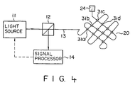
- Fig. 4 shows a method of installing an optical fiber 13 when temperature measurement positions are distributed on a flat surface.
- the optical fiber 13 is installed to form a meander so as path in a measurement region 20 in one direction and to zigzag to substantially perpendicularly cross the zigzag path, thus finally forming a mesh-like structure.
- Portions of the optical fiber 13 which cross each other constitute measurement portions 31a, 31b, ....
- Fig. 5 shows a case wherein a plurality of mesh-like optical fibers, each of which is formed in the same manner as described with reference to Fig. 4, are arranged such that the optical fiber 13 is formed into a three-dimensional structure.
- Fig. 6 schematically shows the arrangement in Fig. 5.
- the temperatures of the measurement portions 31a, 31b, ... are measured in the following procedure with the heaters or cooling devices.
- Reference signals representing only positions or positions and temperatures are acquired from the respective measurement portions 31a, 31b, .... A method of acquiring reference signals will be described below.
- the measurement portions 31a, 31b, ... are separately or simultaneously set at a predetermined temperature, which is sufficiently different from the temperature of the measurement region 20, by using the heaters, the cooling devices, or the like. Subsequently, the light source 11 is driven to radiate the light pulse S on the optical fiber 13.
- the intensity data of backscattered light components which return to the incidence end upon Raman scattering in the optical fiber 13 are supplied to the high speed analytical processor 146 through the characteristic filter or extracting circuit 142 (Fig. 3) and the optical-to-electrical converter 145 (Fig. 3), and are time-serially processed.
- back-scattered light components having intensities different from those of other light components are supplied from the respective measurement portions 31a, 31b, ... at time t1, time t2, ... (reference positions), ..., as shown in Fig. 7A.
- the data processor 147 measures (calculates) temperatures (reference temperatures) at the positions corresponding to time t1, time t2, ... on the basis of signal levels at time t1, time t2, ..., and sequentially stores the time and the temperature in the file 148 (Fig. 3).
- the actually measured temperatures may be corrected (calibrated) by using the above-described reference temperatures.
- a time corresponding to a length Lng ⁇ 2/C ( C is light velocity) is stored in the file .
- the high speed analytical processor 146 measures a time from the instant at which the light source 11 emits a light pulse.
- the high speed analytical processor 146 starts to sample backscattered light components and to store the sampled data in the internal memory at a time point at which the time stored in the file 148 has elapsed.
- measurement of temperatures is mainly described.
- measurement of humidities can be performed in the same manner.
- an optical fiber is two-dimensionally or three-dimensionally arranged, and predetermined positions of the optical fiber are set at a predetermined temperature so as to acquire data in advance.
- the propagation time of light in an optical fiber can be accurately measured.
Landscapes
- Physics & Mathematics (AREA)
- General Physics & Mathematics (AREA)
- Measuring Temperature Or Quantity Of Heat (AREA)
- Investigating, Analyzing Materials By Fluorescence Or Luminescence (AREA)
Claims (14)
- Eine Vorrichtung zum Messen einer Temperatur einer optischen Fasereinrichtung (13) durch Strahlen von Licht auf die optische Fasereinrichtung (13), die eingebaut ist, um mindestens eine Stelle hindurch zu lassen, bei der eine Temperatur zu messen ist, und die Licht überträgt, und Messen von in der optischen Fasereinrichtung (13) erzeugtem Ramangestreutem Licht, mit folgenden Merkmalen:eine Lichtquelleneinrichtung (11,12) zum Strahlen von Licht auf die optische Fasereinrichtung (13);eine Empfangseinrichtung (12; 142 bis 145) zum Empfangen von Raman-gestreutem Licht, das in der optischen Fasereinrichtung (13) als Reaktion auf das auf die optische Fasereinrichtung (13) gestrahlte Licht erzeugt wird, als ein Signal;eine Berechnungseinrichtung (146 bis 149) zum Analysieren des durch die Empfangseinrichtung (12; 142 bis 145) empfangenen Signals und Berechnen einer Position, an der das Raman-gestreute Licht erzeugt wird, und einer Temperatur an dieser Position; undisothermische Kammern zum Halten von Teilen der optischen Fasereinrichtung (13) auf einer vorbestimmten Bezugstemperatur, wobei:die optische Fasereinrichtung (13) eingebaut ist, um eine Meßstelle eine mehrmals durchlaufen zu lassen, unddie Berechnungseinrichtung (146 bis 149) eine Einrichtung zum Empfangen von Raman-gestreutem Licht von Abschnitten der optischen Fasereinrichtung (13) an einer Meßstelle zu unterschiedlichen Timings aufweist, wobei Temperaturen auf der Grundlage des empfangenen Ramangestreuten Lichts erhalten werden, so daß eine Mehrzahl von gemessenen Temperaturen an der einen Meßstelle erhalten wird,
dadurch gekennzeichnet, daßdie optische Fasereinrichtung (13) eingebaut ist, um eine maschenartige Struktur zu bilden, um für jeden durch einen Kreuzungspunkt der maschenartigen Struktur definierten Meßpunkt zwei Temperaturmessungen zu erhalten, wobei die Berechnungseinrichtung eingerichtet ist, um die beiden gemessenen Temperaturen für jeden Meßpunkt zu mitteln. - Eine Vorrichtung gemäß Anspruch 1, dadurch gekennzeichnet, daß die isothermischen Kammern einen oder beide von zwei Abschnitten, die sich an beiden Seiten des durch die Stelle laufenden Abschnitts, an der eine Temperatur zu messen ist, befinden, auf die vorbestimmte Bezugstemperatur einstellt.
- Eine Vorrichtung gemäß Anspruch 1, dadurch gekennzeichnet, daß die isothermischen Kammern eine Temperatur einstellen, die sich beträchtlich von einer geschätzten Temperatur an der Stelle unterscheidet, an der eine Temperatur zu messen ist.
- Eine Vorrichtung gemäß Anspruch 1, dadurch gekennzeichnet, daß die Berechnungseinrichtung (146 bis 149) die Position, an der das Raman-gestreute Licht erzeugt wird, auf der Grundlage des Signals, das die vorbestimmte Temperatur darsteilt, spezifiziert.
- Eine Vorrichtung gemäß Anspruch 1, gekennzeichnet durch eine Einrichtung, um eine Menge von Raman-gestreutem Licht an einer vorbestimmten Position der optischen Fasereinrichtung (13) unterschiedlich von derjenigen von Raman-gestreutem Licht an einem Umfangsabschnitt einzustellen.
- Eine Vorrichtung gemäß Anspruch 1, gekennzeichnet durch eine Speichereinrichtung zum Steuern der Empfangseinrichtung (12; 142 bis 145) und der Berechnungseinrichtung (146 bis 149), um Daten, die die vorbestimmten Positionen darstellen, aus dem Raman-gestreuten Licht zu erhalten und zu speichern, wobei:die Berechnungseinrichtung (146 bis 149) umfaßt:eine Einrichtung zum Spezifizieren des Raman-gestreuten Lichts von einer Meßposition auf der Grundlage der in der Speichereinrichtung bei einer tatsächlichen Temperaturmessung gespeicherten Daten, undeine Einrichtung zum Berechnen einer Temperatur auf der Grundlage des spezifizierten Raman-gestreuten Lichts.
- Eine Vorrichtung gemäß Anspruch 1, dadurch gekennzeichnet, daß die Empfangseinrichtung umfaßt:eine Einrichtung (146) zum Speichern einer Abtastung des empfangenen Raman-gestreuten Lichts;eine Einrichtung (146) zum Speichern eines abgetasteten Signals; undeine Einrichtung zum Verhindern, daß Raman-gestreutes Licht von einem Nicht-Meßabschnitt der optischen Fasereinrichtung in der Speichereinrichtung (146) gespeichert wird.
- Eine Vorrichtung gemäß Anspruch 1, dadurch gekennzeichnet, daß die Berechnungseinrichtung (146 bis 149) eine Laufzeit eines optischen Signals in der optischen Fasereinrichtung (13) auf der Grundlage des die Position darstellenden Signals erhält.
- Eine Vorrichtung gemäß Anspruch 1, dadurch gekennzeichnet, daß die Berechnungseinrichtung (146 bis 149) eine Einrichtung zum Messen einer Feuchtigkeit aus einer Temperaturdifferenz zwischen zwei benachbarten Abschnitten aufweist.
- Ein Verfahren, mit folgenden Schritten:Einbauen einer optischen Faser (13), um mindestens eine Temperaturmeßstelle durchlaufen zu lassen;Strahlen eines optischen Signals auf die optische Faser (13) und kontinuierliches Erzeugen von Raman-gestreutem Licht;Empfangen des Raman-gestreuten Lichts und Messen einer Temperatur der optischen Faser (13) auf der Grundlage des empfangenen Raman-gestreuten Lichts; undAddieren eines Signals, das eine vorbestimmte Position oder Temperatur der optischen Faser (13) darstellt, zu dem Raman-gestreuten Licht, wobei das Signal durch das Ramangestreute Licht gebildet wird, wobei:der Schritt des Einbauens der optischen Faser (13) den Schritt des Einbauens der optischen Faser auf solche Weise umfaßt, daß eine Meßstelle mehrmals durchlaufen gelassen wird, undder Meßschritt den Schritt eines Erhaltens von Temperaturen von Raman-gestreutem Licht aus einer Mehrzahl von Abschnitten an einer Meßstelle umfaßt,
dadurch gekennzeichnet, daßin dem Einbauschritt die optische Faser (13) eingebaut wird, um eine maschenartige Struktur zu bilden, um für jeden durch einen Kreuzungspunkt der maschenartigen Struktur definierten Meßpunkt zwei Temperaturmessungen zu erhalten, die dann in dein Meßschritt gemittelt werden. - Ein Verfahren gemäß Anspruch 10, dadurch gekennzeichnet, daß der Meßschritt den Schritt eines Spezifizierens einer Position, an der das Raman-gestreute Licht erzeugt wird, auf der Grundlage des Signals umfaßt.
- Ein Verfahren gemäß Anspruch 10, dadurch gekennzeichnet, daß der Addierschritt den Schritt eines Einstellens einer vorbestimmten Position der optischen Faser (13) auf eine vorbestimmte Temperatur umfaßt.
- Ein Verfahren gemäß Anspruch 10, dadurch gekennzeichnet, daß der Addierschritt den Schritt eines Anordnens des Abschnitts, bei dem eine Rate eines Auftretens einer Raman-Streuung sich von der Rate an einem Umfangsabschnitt unterscheidet, an einer vorbestimmten Position der optischen Faser (13) umfaßt.
- Ein Verfahren gemäß Anspruch 11, dadurch gekennzeichnet, daß der Meßschritt folgenden Schritte umfaßt:Speichern einer Intensität von empfangenem Ramangestreutem Licht; undBerechnen einer Temperatur aus dem gespeicherten Inhalt, wobei eine Intensität von Raman-gestreutem Licht aus einem Nicht-Meßabschnitt der optischen Faser (13) in dem Speicherschritt nicht gespeichert wird.
Priority Applications (1)
| Application Number | Priority Date | Filing Date | Title |
|---|---|---|---|
| DE1990633445 DE69033445T2 (de) | 1990-05-22 | 1990-05-22 | Gerät und Verfahren zur Temperaturmessung durch Verwendung optischer Fasern |
Applications Claiming Priority (1)
| Application Number | Priority Date | Filing Date | Title |
|---|---|---|---|
| US07/525,725 US5028146A (en) | 1990-05-21 | 1990-05-21 | Apparatus and method for measuring temperatures by using optical fiber |
Publications (2)
| Publication Number | Publication Date |
|---|---|
| EP0457941A1 EP0457941A1 (de) | 1991-11-27 |
| EP0457941B1 true EP0457941B1 (de) | 2000-02-02 |
Family
ID=24094374
Family Applications (1)
| Application Number | Title | Priority Date | Filing Date |
|---|---|---|---|
| EP90109704A Expired - Lifetime EP0457941B1 (de) | 1990-05-21 | 1990-05-22 | Gerät und Verfahren zur Temperaturmessung durch Verwendung optischer Fasern |
Country Status (2)
| Country | Link |
|---|---|
| US (1) | US5028146A (de) |
| EP (1) | EP0457941B1 (de) |
Families Citing this family (32)
| Publication number | Priority date | Publication date | Assignee | Title |
|---|---|---|---|---|
| EP0553675A1 (de) * | 1992-01-29 | 1993-08-04 | Siemens Aktiengesellschaft | Verfahren und Vorrichtung zur Überwachung der Temperatur in einem Turbinenbauteil |
| US5356220A (en) * | 1992-05-29 | 1994-10-18 | Kawasaki Steel Corporation | Method and apparatus for monitoring temperature of blast furnace and temperature control system using temperature monitoring apparatus |
| US5449233A (en) * | 1992-06-16 | 1995-09-12 | Kabushiki Kaisha Toshiba | Temperature distribution measuring apparatus using an optical fiber |
| JPH06136678A (ja) * | 1992-10-29 | 1994-05-17 | Toshiba Corp | 連続蒸解釜温度分布制御装置 |
| KR0133488B1 (en) * | 1993-01-06 | 1998-04-23 | Toshiba Kk | Temperature distribution detector using optical fiber |
| US5839830A (en) * | 1994-09-19 | 1998-11-24 | Martin Marietta Energy Systems, Inc. | Passivated diamond film temperature sensing probe and measuring system employing same |
| US5663490A (en) * | 1995-04-14 | 1997-09-02 | Daito Kogyo Co., Ltd. | Breakage detection system for water-barrier sheet in waste disposal facility |
| GB9508427D0 (en) * | 1995-04-26 | 1995-06-14 | Electrotech Equipments Ltd | Temperature sensing methods and apparatus |
| JP3224344B2 (ja) * | 1996-06-10 | 2001-10-29 | 安藤電気株式会社 | 多分岐光線路試験装置 |
| DE19738651A1 (de) * | 1997-09-04 | 1999-03-11 | Alsthom Cge Alcatel | Vorrichtung zur Ermittlung der Temperatur eines Objekts und Verfahren zur Herstellung einer solchen Vorrichtung |
| SE514744C2 (sv) | 1999-07-06 | 2001-04-09 | Samba Sensors Ab | Förfarande och anordning vid optiska mätsystem |
| DE10111640A1 (de) * | 2001-03-10 | 2002-10-02 | Airbus Gmbh | Verfahren zur Ermittlung und Meldung von Überhitzungen und Feuern in einem Flugzeug |
| US20030234921A1 (en) * | 2002-06-21 | 2003-12-25 | Tsutomu Yamate | Method for measuring and calibrating measurements using optical fiber distributed sensor |
| WO2004074821A1 (en) * | 2003-02-20 | 2004-09-02 | Sensor Highway Limited | Temperature compensation to an optical fibre sensor for measuring moisture |
| WO2004104536A1 (en) * | 2003-05-23 | 2004-12-02 | Sensor Highway Limited | Distributed temperature sensing system with remote reference coil |
| FR2903773B1 (fr) * | 2006-07-13 | 2009-05-08 | Bidim Geosynthetics Soc Par Ac | Dispositif, systeme et procede de detection et de localisation de dysfonctionnement dans un ouvrage hydraulique, ainsi qu'un ouvrage hydraulique equipe de ce dispositif. |
| US7509008B2 (en) * | 2006-10-06 | 2009-03-24 | Halliburton Energy Services, Inc. | Method and apparatus for locating a localized temperature change in a workspace |
| RU2434208C2 (ru) * | 2007-01-30 | 2011-11-20 | Курков Андрей Семенович | Волоконно-оптическое устройство для измерения распределения температуры (варианты) |
| US8201996B1 (en) | 2008-04-25 | 2012-06-19 | Ipitek, Inc. | Passive wavelength-division multiplexing (WDM) fiber-optic temperature sensor |
| US8206030B1 (en) | 2008-05-19 | 2012-06-26 | Ipitek, Inc. | Multiple sensing tip optical fiber thermometer |
| US8075181B1 (en) * | 2008-05-29 | 2011-12-13 | The Regents Of The University Of California | Thermal monitoring device |
| US8109335B2 (en) * | 2009-07-13 | 2012-02-07 | Halliburton Energy Services, Inc. | Degradable diverting agents and associated methods |
| DE102009039259B4 (de) * | 2009-08-28 | 2016-07-28 | Sms Group Gmbh | Überwachung von Walzenlagern |
| US8016034B2 (en) | 2009-09-01 | 2011-09-13 | Halliburton Energy Services, Inc. | Methods of fluid placement and diversion in subterranean formations |
| GB2490086B (en) * | 2010-11-08 | 2015-04-08 | Silixa Ltd | Fibre optic monitoring installation, apparatus and method |
| US20130048282A1 (en) | 2011-08-23 | 2013-02-28 | David M. Adams | Fracturing Process to Enhance Propping Agent Distribution to Maximize Connectivity Between the Formation and the Wellbore |
| WO2013183126A1 (ja) * | 2012-06-06 | 2013-12-12 | 東芝三菱電機産業システム株式会社 | 光ファイバ温度センサ |
| JP6160083B2 (ja) * | 2013-01-08 | 2017-07-12 | 株式会社Ihi | 異物検知装置 |
| JP5742861B2 (ja) * | 2013-02-28 | 2015-07-01 | 横河電機株式会社 | 光ファイバ温度分布測定装置 |
| JP6284051B2 (ja) * | 2016-02-25 | 2018-02-28 | 横河電機株式会社 | 光ファイバ温度分布測定システムおよび光ファイバ温度分布測定方法 |
| CN116878687A (zh) * | 2023-03-27 | 2023-10-13 | 北京邮电大学 | 一种基于分布式光纤传感的建筑物热浪预警方法及装置 |
| US12540866B2 (en) * | 2023-05-15 | 2026-02-03 | Lambdascope | Fiber optic based temperature sensor |
Family Cites Families (10)
| Publication number | Priority date | Publication date | Assignee | Title |
|---|---|---|---|---|
| US2915898A (en) * | 1956-11-30 | 1959-12-08 | Gen Electric | Device for direct measurement of relative humidity |
| US3986775A (en) * | 1974-12-26 | 1976-10-19 | The United States Of America As Represented By The Secretary Of The Navy | Remote measurement of fluid temperature by raman scattered radiation |
| US4008961A (en) * | 1975-04-21 | 1977-02-22 | Allied Chemical Corporation | Monochromatic detection of plural rotational Raman spectra generated by multiple frequency excitation |
| GB2140554A (en) * | 1983-05-26 | 1984-11-28 | Plessey Co Plc | Temperature measuring arrangement |
| GB2156513B (en) * | 1984-03-28 | 1988-05-25 | Plessey Co Plc | Temperature measuring arrangements |
| GB2170593B (en) * | 1985-02-01 | 1988-09-14 | Central Electr Generat Board | Temperature measurement |
| GB8520827D0 (en) * | 1985-08-20 | 1985-09-25 | York Ventures & Special Optica | Fibre-optic sensing devices |
| GB2181830B (en) * | 1985-10-18 | 1990-02-07 | Central Electr Generat Board | Temperature measurement |
| GB2199655A (en) * | 1986-12-10 | 1988-07-13 | Plessey Co Plc | Optical sensing system |
| GB8730061D0 (en) * | 1987-12-23 | 1988-02-03 | Plessey Co Plc | Improvements relating to optical sensing systems |
-
1990
- 1990-05-21 US US07/525,725 patent/US5028146A/en not_active Expired - Lifetime
- 1990-05-22 EP EP90109704A patent/EP0457941B1/de not_active Expired - Lifetime
Also Published As
| Publication number | Publication date |
|---|---|
| US5028146A (en) | 1991-07-02 |
| EP0457941A1 (de) | 1991-11-27 |
Similar Documents
| Publication | Publication Date | Title |
|---|---|---|
| EP0457941B1 (de) | Gerät und Verfahren zur Temperaturmessung durch Verwendung optischer Fasern | |
| EP3014222B1 (de) | Verbesserungen an einer verteilten glasfasersensorik | |
| CA1265938A (en) | Temperature measurement | |
| EP3376169B1 (de) | Temperatur- oder dehnungsverteilungssensor | |
| US20110231135A1 (en) | Auto-correcting or self-calibrating DTS temperature sensing systems and methods | |
| JP5232982B2 (ja) | 光ファイバ位置特定のための光学マーキング部を備えた光ファイバセンサおよび光ファイバセンサの計測方法と光ファイバセンサ装置 | |
| JP5413931B2 (ja) | 光ファイバ位置特定のための光学マーキング部を備えた光ファイバセンサおよび光ファイバセンサの計測方法と光ファイバセンサ装置 | |
| US9958300B2 (en) | Time division multiplexing (TDM) and wavelength division multiplexing (WDM) fast-sweep interrogator | |
| CN110440838B (zh) | 一种基于多芯光纤的多参量光纤传感仪器和传感方法 | |
| US20160168980A1 (en) | Dual-ended distributed temperature sensor with temperature sensor array | |
| JP2018146371A (ja) | 温度・歪センシング装置及び温度・歪センシング方法 | |
| US9897470B2 (en) | Device for characterizing a physical phenomenon by ablation of an optical fiber with bragg gratings having a total flux of reflected radiation measurement | |
| GB2414796A (en) | Optical wavelength determination using multiple measurable features | |
| JPH0663872B2 (ja) | 分布温度センサ | |
| CN110440837B (zh) | 一种多参量光纤同步传感采集仪和传感采集方法 | |
| US8797541B2 (en) | Optical network configuration with intrinsic delay for swept-wavelength interferometry systems | |
| CN102506916B (zh) | 采用弱反射fbg的分布式传感网络及其各fbg的精确定位方法 | |
| US20040208413A1 (en) | Cryogenic optical fibre temperature sensor | |
| CN118119826A (zh) | 测量光纤中的温度和/或应变的方法和装置 | |
| JPH0712655A (ja) | 測定システム | |
| JP2693746B2 (ja) | 測定装置 | |
| US20150276686A1 (en) | Systems and methods for addressing one or more sensors along a cable | |
| CN105371980A (zh) | 一种文物遗址温度监测系统及监测方法 | |
| WO2019185616A1 (en) | Sensor system | |
| KR930006308B1 (ko) | 광섬유를 이용한 온도 측정 장치 및 그 방법 |
Legal Events
| Date | Code | Title | Description |
|---|---|---|---|
| PUAI | Public reference made under article 153(3) epc to a published international application that has entered the european phase |
Free format text: ORIGINAL CODE: 0009012 |
|
| 17P | Request for examination filed |
Effective date: 19900619 |
|
| AK | Designated contracting states |
Kind code of ref document: A1 Designated state(s): DE FR GB |
|
| 17Q | First examination report despatched |
Effective date: 19930721 |
|
| GRAG | Despatch of communication of intention to grant |
Free format text: ORIGINAL CODE: EPIDOS AGRA |
|
| GRAG | Despatch of communication of intention to grant |
Free format text: ORIGINAL CODE: EPIDOS AGRA |
|
| GRAH | Despatch of communication of intention to grant a patent |
Free format text: ORIGINAL CODE: EPIDOS IGRA |
|
| GRAH | Despatch of communication of intention to grant a patent |
Free format text: ORIGINAL CODE: EPIDOS IGRA |
|
| GRAA | (expected) grant |
Free format text: ORIGINAL CODE: 0009210 |
|
| AK | Designated contracting states |
Kind code of ref document: B1 Designated state(s): DE FR GB |
|
| REF | Corresponds to: |
Ref document number: 69033445 Country of ref document: DE Date of ref document: 20000309 |
|
| ET | Fr: translation filed | ||
| PLBE | No opposition filed within time limit |
Free format text: ORIGINAL CODE: 0009261 |
|
| STAA | Information on the status of an ep patent application or granted ep patent |
Free format text: STATUS: NO OPPOSITION FILED WITHIN TIME LIMIT |
|
| 26N | No opposition filed | ||
| REG | Reference to a national code |
Ref country code: GB Ref legal event code: IF02 |
|
| PGFP | Annual fee paid to national office [announced via postgrant information from national office to epo] |
Ref country code: FR Payment date: 20020508 Year of fee payment: 13 |
|
| PGFP | Annual fee paid to national office [announced via postgrant information from national office to epo] |
Ref country code: GB Payment date: 20020522 Year of fee payment: 13 |
|
| PGFP | Annual fee paid to national office [announced via postgrant information from national office to epo] |
Ref country code: DE Payment date: 20020529 Year of fee payment: 13 |
|
| PG25 | Lapsed in a contracting state [announced via postgrant information from national office to epo] |
Ref country code: GB Free format text: LAPSE BECAUSE OF NON-PAYMENT OF DUE FEES Effective date: 20030522 |
|
| PG25 | Lapsed in a contracting state [announced via postgrant information from national office to epo] |
Ref country code: DE Free format text: LAPSE BECAUSE OF NON-PAYMENT OF DUE FEES Effective date: 20031202 |
|
| GBPC | Gb: european patent ceased through non-payment of renewal fee |
Effective date: 20030522 |
|
| PG25 | Lapsed in a contracting state [announced via postgrant information from national office to epo] |
Ref country code: FR Free format text: LAPSE BECAUSE OF NON-PAYMENT OF DUE FEES Effective date: 20040130 |
|
| REG | Reference to a national code |
Ref country code: FR Ref legal event code: ST |