EP0458049A2 - Corps creux pour transporter un fluide, et son application - Google Patents
Corps creux pour transporter un fluide, et son application Download PDFInfo
- Publication number
- EP0458049A2 EP0458049A2 EP91105693A EP91105693A EP0458049A2 EP 0458049 A2 EP0458049 A2 EP 0458049A2 EP 91105693 A EP91105693 A EP 91105693A EP 91105693 A EP91105693 A EP 91105693A EP 0458049 A2 EP0458049 A2 EP 0458049A2
- Authority
- EP
- European Patent Office
- Prior art keywords
- hollow body
- body according
- outer tube
- tube
- sheet metal
- Prior art date
- Legal status (The legal status is an assumption and is not a legal conclusion. Google has not performed a legal analysis and makes no representation as to the accuracy of the status listed.)
- Withdrawn
Links
Images

Classifications
-
- B—PERFORMING OPERATIONS; TRANSPORTING
- B21—MECHANICAL METAL-WORKING WITHOUT ESSENTIALLY REMOVING MATERIAL; PUNCHING METAL
- B21D—WORKING OR PROCESSING OF SHEET METAL OR METAL TUBES, RODS OR PROFILES WITHOUT ESSENTIALLY REMOVING MATERIAL; PUNCHING METAL
- B21D51/00—Making hollow objects
-
- F—MECHANICAL ENGINEERING; LIGHTING; HEATING; WEAPONS; BLASTING
- F01—MACHINES OR ENGINES IN GENERAL; ENGINE PLANTS IN GENERAL; STEAM ENGINES
- F01N—GAS-FLOW SILENCERS OR EXHAUST APPARATUS FOR MACHINES OR ENGINES IN GENERAL; GAS-FLOW SILENCERS OR EXHAUST APPARATUS FOR INTERNAL-COMBUSTION ENGINES
- F01N13/00—Exhaust or silencing apparatus characterised by constructional features
- F01N13/18—Construction facilitating manufacture, assembly, or disassembly
- F01N13/1838—Construction facilitating manufacture, assembly, or disassembly characterised by the type of connection between parts of exhaust or silencing apparatus, e.g. between housing and tubes, between tubes and baffles
- F01N13/1844—Mechanical joints
- F01N13/185—Mechanical joints the connection being realised by deforming housing, tube, baffle, plate, or parts thereof
-
- F—MECHANICAL ENGINEERING; LIGHTING; HEATING; WEAPONS; BLASTING
- F01—MACHINES OR ENGINES IN GENERAL; ENGINE PLANTS IN GENERAL; STEAM ENGINES
- F01N—GAS-FLOW SILENCERS OR EXHAUST APPARATUS FOR MACHINES OR ENGINES IN GENERAL; GAS-FLOW SILENCERS OR EXHAUST APPARATUS FOR INTERNAL-COMBUSTION ENGINES
- F01N13/00—Exhaust or silencing apparatus characterised by constructional features
- F01N13/14—Exhaust or silencing apparatus characterised by constructional features having thermal insulation
-
- F—MECHANICAL ENGINEERING; LIGHTING; HEATING; WEAPONS; BLASTING
- F16—ENGINEERING ELEMENTS AND UNITS; GENERAL MEASURES FOR PRODUCING AND MAINTAINING EFFECTIVE FUNCTIONING OF MACHINES OR INSTALLATIONS; THERMAL INSULATION IN GENERAL
- F16L—PIPES; JOINTS OR FITTINGS FOR PIPES; SUPPORTS FOR PIPES, CABLES OR PROTECTIVE TUBING; MEANS FOR THERMAL INSULATION IN GENERAL
- F16L9/00—Rigid pipes
- F16L9/16—Rigid pipes wound from sheets or strips, with or without reinforcement
- F16L9/165—Rigid pipes wound from sheets or strips, with or without reinforcement of metal
-
- F—MECHANICAL ENGINEERING; LIGHTING; HEATING; WEAPONS; BLASTING
- F01—MACHINES OR ENGINES IN GENERAL; ENGINE PLANTS IN GENERAL; STEAM ENGINES
- F01N—GAS-FLOW SILENCERS OR EXHAUST APPARATUS FOR MACHINES OR ENGINES IN GENERAL; GAS-FLOW SILENCERS OR EXHAUST APPARATUS FOR INTERNAL-COMBUSTION ENGINES
- F01N2450/00—Methods or apparatus for fitting, inserting or repairing different elements
- F01N2450/20—Methods or apparatus for fitting, inserting or repairing different elements by mechanical joints, e.g. by deforming housing, tube, baffle plate or parts thereof
-
- F—MECHANICAL ENGINEERING; LIGHTING; HEATING; WEAPONS; BLASTING
- F01—MACHINES OR ENGINES IN GENERAL; ENGINE PLANTS IN GENERAL; STEAM ENGINES
- F01N—GAS-FLOW SILENCERS OR EXHAUST APPARATUS FOR MACHINES OR ENGINES IN GENERAL; GAS-FLOW SILENCERS OR EXHAUST APPARATUS FOR INTERNAL-COMBUSTION ENGINES
- F01N2470/00—Structure or shape of exhaust gas passages, pipes or tubes
- F01N2470/02—Tubes being perforated
-
- F—MECHANICAL ENGINEERING; LIGHTING; HEATING; WEAPONS; BLASTING
- F01—MACHINES OR ENGINES IN GENERAL; ENGINE PLANTS IN GENERAL; STEAM ENGINES
- F01N—GAS-FLOW SILENCERS OR EXHAUST APPARATUS FOR MACHINES OR ENGINES IN GENERAL; GAS-FLOW SILENCERS OR EXHAUST APPARATUS FOR INTERNAL-COMBUSTION ENGINES
- F01N2470/00—Structure or shape of exhaust gas passages, pipes or tubes
- F01N2470/12—Tubes being corrugated
Definitions
- the invention relates to a hollow body for the passage of fluids, with an essentially oval or circular cross-section over its longitudinal extent, with an outer tube made of metal, which is formed by helically wound sheet metal strips connected to one another by folds at their abutting outer edges, and a method for the production thereof and the use of the hollow body.
- Hollow bodies for the passage of a fluid such as, for example, mufflers, filters or pipes, have hitherto generally been produced from a large number of individual sheet-metal pressed parts by welding and / or folding. The workload is considerable, the need for tools is great.
- the invention has for its object to provide a hollow body for the passage of fluids with almost any diameter, which is simple and therefore inexpensive to manufacture, which has good performance properties and which can optionally be installed with considerable speed.
- the outer tube has at least two walls and is produced by jointly winding and folding a number of continuous sheet metal strips of identical width corresponding to the number of outer tube walls.
- a material saving of approx. 35% occurs with the same compressive or transverse strength.
- the hollow body is used as a muffler, the outer tube then being sealed in an essentially gas-tight manner by cover plates, not only can a smaller structure-borne noise be observed due to the multi-walled design, the desired damping can in turn also be compared to known mufflers with a material saving of the order of magnitude 35% can be realized.
- An embodiment of the invention provides that Multi-walled outer tube at least the inner single tube is provided with openings allowing fluid to pass through.
- the openings are formed by punched holes.
- the invention optionally also proposes that at least some of the openings be formed by slits and / or bulges in the tube sheet.
- the bulges are semi-conical, the base of the hollow cone forming the openings.
- Another embodiment of the invention is characterized in that at least the inner single tube consists of thin-walled stainless steel sheet.
- an absorbent, damping and / or insulating intermediate layer such as a mineral fiber layer, plastic, lead or, at least in the annular gap between the inner single tube and the tube adjoining it to the outside, possibly the outer tube of the outer tube the like, is arranged.
- the invention also proposes that the gusset formed on the inside of the fold seam is filled with a sealing and / or vibration-damping insert.
- the insert is formed by a correspondingly shaped metal wire during folding.
- Another embodiment of the invention is characterized in that the sheet metal strip (s) is / are provided with stiffening ribs.
- two intermediate floors made of sheet metal or the like are provided with a plurality of holes; that a feed pipe passes through the cover plate closest to the feed end of the muffler and the intermediate floor nearest this and opens into a feed pipe opening of the other intermediate floor; and that a discharge pipe passes through the other cover plate and the intermediate floor closest to it and opens into a discharge pipe opening of the supply-side intermediate floor.
- a special embodiment is characterized in that the feed pipe is provided with gas passage openings in the area between the two intermediate floors.
- a further embodiment of the invention provides that the feed pipe, the discharge pipe, at least one of the intermediate floors and / or at least one of the cover plates consists of stainless steel plate.
- the feed pipe and / or the discharge pipe run essentially straight within the muffler.
- Another embodiment of the invention provides that the substantially gas-tight connection between the Outer tube, the cover plates, the intermediate floors and / or the feed and / or discharge pipe is produced without a weld seam or the like by folding.
- the three chambers formed by the feed-side cover plate and the feed-side intermediate plate, the two intermediate plates and the discharge-side intermediate plate and the discharge-side cover plate communicate via the annular gap adjoining the inner individual tube to the outside in a shunt.
- the outer tube can consist of at least two individual tubes which are arranged one inside the other at a predetermined distance. In this way, different fluid-tight chambers are formed, in which several fluids, which must not mix with one another, can be transported, for example when used as a pipeline.
- the individual tubes are arranged essentially concentrically to one another.
- the hollow body can also have a polygonal cross section, preferably a triangular, square or hexagonal cross section.
- corner radii should be at least 40 mm.
- the method according to the invention is characterized by common spiral or helical winding and folding of at least two bleaching strips of identical width to form long tubes with different diameters and a length which is a multiple of the length of the hollow body to be produced, and cutting the long tubes at regular intervals to the length of the hollow body to be produced.
- the winding and folding of the sheet metal strip (s) be carried out on a laying vehicle moving forward according to the production speed of the hollow body produced.
- the hollow body is used not only as a muffler, filter or the like, but also as a pipe - or as a component thereof - for the transport of natural or synthetic hydrocarbons or mixtures thereof in gaseous or liquid form, such as natural gas, petroleum, petroleum derivatives or the like , further for transporting a large number of fluids which are not to be mixed, at least one number of inner tubes and / or outer tubes corresponding to the number of fluids preferably being arranged concentrically one inside the other.
- a hollow body, which is designed in particular according to claim 7, can be used as a radiation protection barrel or a chemical-resistant barrel.
- Another use according to the invention includes the simultaneous carrying of a power cable, although a multi-walled design of the outer tube is not necessary, rather it is sufficient to provide this with a single wall.
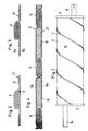
- the hollow body according to the invention has an outer tube 21, which is made from a helically wound sheet metal strip, in which the abutting outer edges of the sheet metal strips are folded together in a fold seam 11.
- the cylindrical hollow body which of course does not necessarily have to be circular-cylindrical, is closed at its ends in a known manner by a feed-side cover plate 12 and a discharge-side cover plate 13, with a feed pipe in the feed-side cover plate 12 in the hollow body serving as a silencer in FIG. 1 14 and a discharge pipe 15 are inserted into the discharge-side cover plate 13.
- the gases to be passed through the hollow body e.g. Exhaust gases from a motor vehicle, thus penetrate the interior of the hollow body from FIG. 1 from the supply pipe 14 in the direction of the discharge pipe 15.
- FIG. 2 shows details of the fold seam 11 according to the prior art, in which the abutting outer edges of the metal strips 10 are tightly connected to one another.
- An insert 17 is inserted into the gusset which forms in the region of the bend of the sheet metal strips 10 and fills the gusset and is flush with the inside of the wall of the sheet metal strip 10.
- This insert can consist of a plastic strip, but a metal wire made of a relatively soft material is preferably chosen, which completely adapts to the shape of the gusset when folded.
- FIG. 3 corresponds to that of FIG. 2 with the difference that the outer tube 21 according to the invention has two walls 10a, 10b, which consist of corresponding sheet metal strips placed one on top of the other or entering the folding device together are formed.
- FIG. 4 shows a representation corresponding to FIG. 3, the annular gap between the two walls 10a, 10b in the region outside of the fold seam 11 being filled by a heat and / or sound insulating and / or sound or heat insulating intermediate layer 16. 3 and 4, the gusset in the fold seam 11 can of course be closed by an insert 17, as shown in FIG. 2.
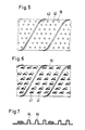
- sheet metal strips 10 are shown, which show that the individual tubes shown in sections there can be provided with interruptions 41, 43.
- the openings in FIG. 6 are formed by simple holes punched into the metal strip 10.
- the sheet metal strip 10 is provided with a plurality of slits and semi-cone-shaped bulges adjoining the slits, the approximately semicircular base areas forming the openings.
- Fig. 8 it is shown that the sheet metal strips can be provided with stiffening ribs 44.
- the outer tube 21, within which the inner tube 27 is arranged at a radial distance with the formation of an annular gap filled with an insulating or damping intermediate layer, is again provided on the front side with the feed-side cover plate 12 and the discharge-side cover plate 13.
- two intermediate floors 46, 48 made of stainless steel are arranged essentially transversely to the longitudinal axis thereof at a mutual distance and at a distance from the cover plate 12 or the cover plate 13.
- the feed tube 14 passes through the cover plate 12 and the intermediate base 46 and opens openly into a corresponding feed tube opening in the intermediate base 48. In the area between the intermediate base 46 and the intermediate base 48, the feed tube 14 is provided with gas passage openings 50.
- the discharge pipe 15 passes through the cover plate 13 and the intermediate floor 48 and opens openly into a feed pipe opening of the intermediate floor 46.
- the chambers which pass through the cover plate 12 and the intermediate floor 46 on the one hand, the two intermediate floors 46, 48 on the other hand and the intermediate floor 48 and the cover plate 13 are formed, are in a shunt connection over the annular gap between the outer tube of the outer tube 21 and the inner single tube 27 thereof.
- the intermediate floors 46, 48 are provided with perforations in the manner shown in FIG. 10 - FIG. 9 shows the arrangement of the feed tube 14 within the cover plate 12.
- the arrangement of the perforations in the intermediate floors 46, 48 in conjunction with the corresponding openings in the inner single tube 27 and the shunt across the annular gap outside the inner single tube 27, combined with the gas passage openings 50 of the feed pipe 14 in the section between the two intermediate floors 46 and 48 achieves excellent sound absorption.
- the muffler can be produced inexpensively without the use of welded connections, the preferred configuration of all stainless steel muffler surfaces coming into contact with the exhaust gases resulting in high corrosion resistance, which is further promoted by the absence of any welded connections.
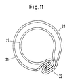
- FIG. 11 shows an embodiment of the hollow body according to the invention, in which the inner individual tube 27 is arranged at a certain, relatively small distance from the outer tube 21. Both tubes are combined at the fold point 22.
- This arrangement creates a cavity 28 between the inner individual tube 27 and the outer tube 21, through which, for example, cooling liquid can be passed, but which, if desired, is also suitable for receiving insulating material.
- the substance with which the cavity 28 is filled depends on the intended use of the hollow body. If it is to be used as a radiation protection barrel, it is advisable to introduce 28 lead into the cavity. When used as a chemical-resistant barrel or as a chemical-resistant pipeline, it can be foamed with a suitable plastic.
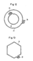
- FIG. 12 A modification of the embodiment from FIG. 11 is shown in FIG. 12. If an absolute fluid seal is required, two inter-lying double-walled tubes 23, 25 should be used, each of which is closed with the helical fold 24, 26 according to the invention.
- a hollow body of this type is particularly suitable if different fluids are conveyed which must not mix. This can be the case in particular if a gas and a liquid are to be transported at the same time.
- a hollow body according to the present invention can also have a polygonal cross section, as shown using the example of a hexagonal cross section in FIG. 13.
- Such "parquettable" cross sections are particularly suitable if the hollow bodies are to be packed tightly. If this is desired, the fold 22 should be fitted as far as possible into the inner region of the hollow body, so that the outer tube 21 has an almost ideal shape.
- the hollow body according to the invention can also be used as a pipeline, this pipeline being able to be set up at the point of use. Due to the fact that the hollow body is wound from sheet metal strips according to the invention, it is possible to mount a corresponding device for producing the corresponding hollow body on a vehicle, such as a heavy truck, which can then be moved at the appropriate feed rate, for example about ten meters per minute. drives ahead and places the pipe wrapped in place on the truck behind it.
- a vehicle such as a heavy truck
- the pipeline according to the invention can be used in addition to the already described applications, ie transport of hydrocarbons, such as petroleum or the like, for example, chemical Transport substances or suspensions of solids in liquids. If it is a question of using liquids which have to be cooled during transport, as is the case, for example, in the case of natural gas transport by means of double-walled pipeline pipes which have already been used and in which there is a cooling liquid in the hollow jacket, the invention is particularly advantageous realize such a hollow jacket tube, namely that the outer tube consists of two individual tubes wound at a relatively short distance.
- the invention makes it possible to send two or more different media through a single cylindrical hollow body of the type according to the invention, in the interior of which, preferably concentrically, various further hollow bodies are arranged, the individual hollow bodies or pipes according to the invention, as it were, from the inside can be made concentrically one after the other in the manner described.
- this also makes it possible to transport substances that require cooling or insulation during transport, both in the gaseous and in the liquid state, and also in the supercooled state, with an integrated monitoring system (sensor technology) in the outer shell of the outermost hollow body can be attached.
- the hollow body according to the invention is characterized by an extreme voltage absorption, it can also be used for power cable laying. It is advantageous here to run the cables in a single-walled tube, since this can optimally absorb the stresses occurring due to the helical arrangement of the fold, so that destruction of the cable is not to be expected.
Landscapes
- Engineering & Computer Science (AREA)
- Mechanical Engineering (AREA)
- General Engineering & Computer Science (AREA)
- Chemical & Material Sciences (AREA)
- Combustion & Propulsion (AREA)
- Rigid Pipes And Flexible Pipes (AREA)
- Soundproofing, Sound Blocking, And Sound Damping (AREA)
Priority Applications (2)
| Application Number | Priority Date | Filing Date | Title |
|---|---|---|---|
| KR1019910007675A KR910019699A (ko) | 1990-05-22 | 1991-05-13 | 유체통과용 중공체, 그 제조방법 및 중공체의 이용 |
| JP3115763A JPH05133497A (ja) | 1990-05-22 | 1991-05-21 | 流体を貫流案内するための中空体、この中空体を製造するための方法及びこの中空体の使用法 |
Applications Claiming Priority (4)
| Application Number | Priority Date | Filing Date | Title |
|---|---|---|---|
| DE4016743 | 1990-05-22 | ||
| DE19904016743 DE4016743A1 (de) | 1990-05-22 | 1990-05-22 | Hohlkoerper, insbesondere schalldaempfer, zum durchfuehren eines fluids und verfahren zu dessen herstellung |
| DE4030844 | 1990-09-26 | ||
| DE4030844A DE4030844A1 (de) | 1990-05-22 | 1990-09-26 | Verwendung eines hohlkoerpers zum durchfuehren von fluiden als rohrleitung zum transport von kohlenwasserstoffen oder dergleichen, verfahren zur herstellung einer derartigen rohrleitung sowie danach hergestellte rohrleitung |
Publications (2)
| Publication Number | Publication Date |
|---|---|
| EP0458049A2 true EP0458049A2 (fr) | 1991-11-27 |
| EP0458049A3 EP0458049A3 (en) | 1992-04-01 |
Family
ID=25893515
Family Applications (1)
| Application Number | Title | Priority Date | Filing Date |
|---|---|---|---|
| EP19910105693 Withdrawn EP0458049A3 (en) | 1990-05-22 | 1991-04-10 | Hollow body for conveying fluid, manufacturing process and application |
Country Status (4)
| Country | Link |
|---|---|
| EP (1) | EP0458049A3 (fr) |
| KR (1) | KR910019699A (fr) |
| BR (1) | BR9102067A (fr) |
| DE (1) | DE4030844A1 (fr) |
Cited By (5)
| Publication number | Priority date | Publication date | Assignee | Title |
|---|---|---|---|---|
| EP0692324A1 (fr) * | 1994-07-13 | 1996-01-17 | Gerhard Pirchl | Procédé de montage d'une tÔle de blindage thermiquement isolée partiellement et écran de protection thermique avec tÔle de blindage thermiquement isolée attachée à celui-ci |
| WO1996036415A1 (fr) * | 1995-05-18 | 1996-11-21 | Parker-Hannifin Corporation | Cartouche filtrante a couches composees liee par resine |
| WO1999005403A1 (fr) * | 1997-07-24 | 1999-02-04 | Emitec Gesellschaft Für Emissionstechnologie Mbh | Systeme de retenue pour corps porteur dans un tube de protection |
| CN105229357A (zh) * | 2013-05-27 | 2016-01-06 | 株式会社国产螺旋管 | 挠性管、挠性软管和挠性管的制造方法 |
| CN114923044A (zh) * | 2022-06-23 | 2022-08-19 | 浙江大学 | 一种螺旋焊缝余高打磨的减阻性保温管道及其减阻方法 |
Families Citing this family (1)
| Publication number | Priority date | Publication date | Assignee | Title |
|---|---|---|---|---|
| KR100747968B1 (ko) * | 2001-11-15 | 2007-08-08 | 유영태 | 유압 진동유동 발생장치 |
Family Cites Families (11)
| Publication number | Priority date | Publication date | Assignee | Title |
|---|---|---|---|---|
| US1761034A (en) * | 1927-12-01 | 1930-06-03 | Edwin J Elting | Tube |
| US3474514A (en) * | 1965-04-06 | 1969-10-28 | Jack P Lombardi | Apparatus for making spiral seamed corrugated laminated pipe with uncorrugated interior |
| DE6809613U (de) * | 1968-12-02 | 1969-04-30 | Westerbarkey Westaflex | Falzdichtung |
| FR2032737A5 (fr) * | 1969-02-04 | 1970-11-27 | Hess Rainer | |
| DE2045069A1 (fr) * | 1970-09-11 | 1972-03-16 | Siegwart Emil | |
| US3777502A (en) * | 1971-03-12 | 1973-12-11 | Newport News Shipbuilding Dry | Method of transporting liquid and gas |
| US3857159A (en) * | 1973-09-27 | 1974-12-31 | Pacific Roller Die Co Inc | Pipe forming method |
| DE2738601C2 (de) * | 1977-01-18 | 1986-11-27 | Nihon Radiator Co., Ltd., Tokio/Tokyo | Schalldämpfer |
| DE3604921A1 (de) * | 1986-02-17 | 1987-08-20 | Laco Sa | Verfahren zur gefalzten oder geboerdelten verbindung eines rohres mit einem abschlussteil sowie vorrichtung, insbesondere zur durchfuehrung dieses verfahrens |
| DE3612515A1 (de) * | 1986-04-14 | 1987-10-15 | Wang Liang Hsiung | Wickelfalzrohr |
| WO1990005873A1 (fr) * | 1988-11-21 | 1990-05-31 | Siemens Aktiengesellschaft | Procede et dispositif pour obtenir un revetement cylindrique dans une cavite allongee |
-
1990
- 1990-09-26 DE DE4030844A patent/DE4030844A1/de not_active Ceased
-
1991
- 1991-04-10 EP EP19910105693 patent/EP0458049A3/de not_active Withdrawn
- 1991-05-13 KR KR1019910007675A patent/KR910019699A/ko not_active Withdrawn
- 1991-05-20 BR BR919102067A patent/BR9102067A/pt unknown
Cited By (7)
| Publication number | Priority date | Publication date | Assignee | Title |
|---|---|---|---|---|
| EP0692324A1 (fr) * | 1994-07-13 | 1996-01-17 | Gerhard Pirchl | Procédé de montage d'une tÔle de blindage thermiquement isolée partiellement et écran de protection thermique avec tÔle de blindage thermiquement isolée attachée à celui-ci |
| WO1996036415A1 (fr) * | 1995-05-18 | 1996-11-21 | Parker-Hannifin Corporation | Cartouche filtrante a couches composees liee par resine |
| US5639370A (en) * | 1995-05-18 | 1997-06-17 | Parker-Hannifin Corporation | Compound layer resin bonded filter cartridge |
| WO1999005403A1 (fr) * | 1997-07-24 | 1999-02-04 | Emitec Gesellschaft Für Emissionstechnologie Mbh | Systeme de retenue pour corps porteur dans un tube de protection |
| CN105229357A (zh) * | 2013-05-27 | 2016-01-06 | 株式会社国产螺旋管 | 挠性管、挠性软管和挠性管的制造方法 |
| US9599256B2 (en) | 2013-05-27 | 2017-03-21 | Kokusan Rasenkan Co., Ltd. | Flexible tube, flexible hose, and manufacturing method of flexible tube |
| CN114923044A (zh) * | 2022-06-23 | 2022-08-19 | 浙江大学 | 一种螺旋焊缝余高打磨的减阻性保温管道及其减阻方法 |
Also Published As
| Publication number | Publication date |
|---|---|
| BR9102067A (pt) | 1991-12-24 |
| DE4030844A1 (de) | 1992-04-09 |
| EP0458049A3 (en) | 1992-04-01 |
| KR910019699A (ko) | 1991-12-19 |
Similar Documents
| Publication | Publication Date | Title |
|---|---|---|
| DE7417030U (de) | Flexibles leitungsrohr zur fortleitung fluessiger oder gasfoermiger medien | |
| DE4303950C1 (de) | In einem inneren und einem äußeren Mantelrohr gehalterter metallischer Wabenkörper, insbesondere Katalysator-Trägerkörper | |
| EP0245738A1 (fr) | Corps métallique en forme de nid d'abeilles, en particulier support pour catalyseur, avec paroi de support, et son procédé de fabrication | |
| EP2873786B1 (fr) | Grand tube à double paroi, utilisation et procédé de fabrication d'un grand tube à double paroi | |
| EP0292836A1 (fr) | Corps creux cylindrique fabriqué d'un profil en matière plastique enroulé en forme d'hélice | |
| EP2284428B1 (fr) | Conduite et son procédé de fabrication | |
| DE102007016149A1 (de) | Metallschlauchanordnung mit Innen- und Außenschlauch | |
| DE2212900A1 (de) | Rohrleitung | |
| EP0458049A2 (fr) | Corps creux pour transporter un fluide, et son application | |
| EP0983425B1 (fr) | Systeme permettant d'eviter les vibrations mecaniques | |
| DE19724263A1 (de) | Radialkatalysator, insbesondere für Kleinmotoren | |
| EP0729911B1 (fr) | Noyau d'enroulement métallique | |
| DE3151845A1 (de) | Wellrohr mit zugentlastung und verfahren zu dessen herstellung aus kunststoff | |
| DE2508984A1 (de) | Auspuffleitung fuer verbrennungsmotoren | |
| DE3878471T2 (de) | Rohr zur innenbeschichtung von unter druck stehenden wasserleitungen. | |
| EP3969690B1 (fr) | Contenant produit à partir d'une bande de tôle courbée de manière hélicoïdale et procédé pour produire un tel contenant | |
| DE4016743C2 (fr) | ||
| DE3814176C2 (de) | Doppelwandige Rohrleitung aus einer Vielzahl endseitig miteinander verbundener Rohrlängen | |
| DE102008027102A1 (de) | Doppelwand-Wellrohr und Formbacken für eine Vorrichtung zur Herstellung eines derartigen Doppelwand-Wellrohres | |
| EP0521247B1 (fr) | Faisceau de conduits pour câbles composé d'une pluralité de tubes en plastique | |
| DE2233572A1 (de) | Flexibler schlauch | |
| DE102018122658A1 (de) | Abgasleitungseinrichtung | |
| CH639170A5 (de) | Flexible wetterlutte. | |
| DE4121657C2 (de) | Kabelführungsrohrbündel aus einer Mehrzahl von Kunststoffrohren | |
| DE9104906U1 (de) | Schraubenlinien- oder ringförmig gewelltes Metallrohr |
Legal Events
| Date | Code | Title | Description |
|---|---|---|---|
| PUAI | Public reference made under article 153(3) epc to a published international application that has entered the european phase |
Free format text: ORIGINAL CODE: 0009012 |
|
| AK | Designated contracting states |
Kind code of ref document: A2 Designated state(s): DE ES FR GB IT SE |
|
| PUAL | Search report despatched |
Free format text: ORIGINAL CODE: 0009013 |
|
| AK | Designated contracting states |
Kind code of ref document: A3 Designated state(s): DE ES FR GB IT SE |
|
| STAA | Information on the status of an ep patent application or granted ep patent |
Free format text: STATUS: THE APPLICATION IS DEEMED TO BE WITHDRAWN |
|
| 18D | Application deemed to be withdrawn |
Effective date: 19921002 |