EP0458074B1 - Pyrotechnische Vorrichtung - Google Patents
Pyrotechnische Vorrichtung Download PDFInfo
- Publication number
- EP0458074B1 EP0458074B1 EP91106460A EP91106460A EP0458074B1 EP 0458074 B1 EP0458074 B1 EP 0458074B1 EP 91106460 A EP91106460 A EP 91106460A EP 91106460 A EP91106460 A EP 91106460A EP 0458074 B1 EP0458074 B1 EP 0458074B1
- Authority
- EP
- European Patent Office
- Prior art keywords
- receptacle
- fuse
- pyrotechnic
- projecting portion
- contact
- Prior art date
- Legal status (The legal status is an assumption and is not a legal conclusion. Google has not performed a legal analysis and makes no representation as to the accuracy of the status listed.)
- Expired - Lifetime
Links
Images


Classifications
-
- F—MECHANICAL ENGINEERING; LIGHTING; HEATING; WEAPONS; BLASTING
- F42—AMMUNITION; BLASTING
- F42B—EXPLOSIVE CHARGES, e.g. FOR BLASTING, FIREWORKS, AMMUNITION
- F42B4/00—Fireworks, i.e. pyrotechnic devices for amusement, display, illumination or signal purposes
-
- F—MECHANICAL ENGINEERING; LIGHTING; HEATING; WEAPONS; BLASTING
- F42—AMMUNITION; BLASTING
- F42B—EXPLOSIVE CHARGES, e.g. FOR BLASTING, FIREWORKS, AMMUNITION
- F42B4/00—Fireworks, i.e. pyrotechnic devices for amusement, display, illumination or signal purposes
- F42B4/30—Manufacture
Definitions
- THE PRESENT INVENTION relates to a pyrotechnic device and more particularly relates to a pyrotechnic device intended to provide a theatrical effect.
- British Patent 1580579 discloses a pyrotechnic device which is in wide use at the present point in time to provide a flash or smoke burst effect.
- This device comprises a receptacle, moulded from plastics material, which is of hollow cylindrical form, having one closed end and one open end. Two pins pass through the closed end, and, on the interior of the receptacle, a fuse wire is connected between the exposed ends of the pins.
- the receptacle is partly filled with an appropriate pyrotechnic material, and is closed by a closure in the form of a sheet of paper adhered to the open mouth of the receptacle.
- the described pyrotechnic device may be inserted in an appropriate socket in a firing box, the socket establishing electric contact with the two pins. An electric current may thus be caused to flow through the fuse wire, which initiates the device.
- the fuse wire ignites the pyrotechnic material, and the paper sheet is ruptured, since the paper sheet is formed of a material which is weaker than the rest of the receptacle.
- the paper closure is not very strong and is easily broken, especially when a plurality of the devices are packed in a single container, since the pins projecting from the base of one receptacle can easily puncture the paper closure on another receptacle.
- the adhesive that is used to secure the paper closure to the receptacle is fragile, and will break or snap if the device is dropped. This means that, in either case, pyrotechnic material may become dispersed, or become lodged in the packaging which represents a signficant fire hazard.
- the device often has to be inserted in the socket under relatively difficult conditions on stage. It is not unknown for stage-hands to panic and then inadvertently put their fingers through the paper, thus releasing the pyrotechnic material. Also, it is difficult to locate the two pins in alignment with the corresponding pair of holes in the socket - this can lead to fumbling. If the pins catch the socket in an awkward way a spark can be developed, which is clearly undesirable where there is pyrotechnic material around.
- the closure Since the closure is only formed of paper, it is possible for moisture to enter the receptacle. This is clearly undesirable, since the presence of moisture may interfere with the operation of the pyrotechnic material. This can be particularly dangerous since when an electric current is passed through the fuse, the pyrotechnic material may not be ignited as intended. The device may, however, ignite as it is being removed from the firing box. This can be very dangerous.
- a maroon which provides the effect of a loud explosion.
- a further device known as a maroon, which provides the effect of a loud explosion.
- Such a device has a charge of pyrotechnic material in a closed plastics material housing of uniform strength. A fuse or initiator in the housing is connected to a trailing lead or flex. In using such a device it has to be located in a special tank, called a "bomb tank", and the trailing lead or flex is connected to appropriate terminals. It is necessary to use the bomb tank since the device actually explodes, dispersing portions of the plastic material housing with considerable force.
- the present invention seeks to provide an improved pyrotechnic device.
- a pyrotechnic device comprising a receptacle, the receptacle containing a charge of pyrotechnic material and means to initiate the charge, the receptacle being sealed, characterised in that the receptacle has part thereof comprising a moulding provided with lines or areas of relative mechanical weakness adapted to rupture on activation of the pyrotechnic material, the lines or areas of mechanical weakness comprising a plurality of relatively thin webs formed in a wall of the moulding.
- the said part is in the form of a dome, and said lines of mechanical weakness extend linearly outwardly from the apex of the dome.
- the receptacle is formed of a housing defining an opening, and a closure connected to the housing to seal the opening, the housing and the closure each being moulded of a plastics material.
- the closure is connected to the housing by means of a screw-threaded engagement.
- the closure may additionally or alternatively be connected to the housing by welding, bonding or adhering.
- the means to initiate the charge by pyrotechnic material comprise a fuse adapted to initiate the charge when an electric current is passed through the fuse.
- the receptacle is provided with a projecting portion carrying a screw-thread for engagement with a corresponding socket, the projecting portion carrying two separate electric contacts which are electrically connected to the fuse, such that when the threaded projecting portion is screwed into an appropriate corresponding socket, an electric current can be passed from the socket through the fuse, to initiate the device.
- the projecting portion is provided on the closure.
- the projecting portion is integrally moulded of plastics material and defines a screw-thread thereon, the projecting portion being provided with two separate metallic contacts which are in electrical contact with the fuse.
- a pyrotechnic device comprising a two-part receptacle, the two parts each being moulded of a plastics material and being secured together to hermetically seal the receptacle, the receptacle containing pyrotechnic material and a fuse to ignite the pyrotechnic material, there being an integrally moulded projecting portion on one of the parts, the portion defining a screw-thread thereon, and being provided with two separate metallic contacts which are in electrical contact with the fuse.
- one electrical contact comprises a ring-shaped contact surrounding the base of the projecting portion and engaging a wire connected to the fuse
- the second contact comprises an element received in a recess at the end of the projecting portion and again in contact with a wire leading to the fuse
- the contact elements each serve to trap part of the respective wire between the contact element and part of the said projection.
- a preferred embodiment of the invention comprises a pyrotechnic device comprising a two-part receptacle formed of plastics material, the two parts being secured together to hermetically seal the receptacle, the receptacle containing pyrotechnic material and a fuse to ignite the pyrotechnic material, the fuse being electrically connected to two contacts forming part of a projecting screw-threaded arrangement on the exterior of the receptacle, part of the receptacle being provided with one or more lines or areas of relative mechanical weakness adapted to rupture when the fuse is operated to activate the pyrotechnic material.
- the invention also relates to a method of making a pyrotechnic device, the method comprising the steps of moulding two plastics material components which can be assembled together to form a closed receptacle, at least one of the components being provided with one or more lines of mechanical weakness which can rupture under applied pressure, each line of mechanical weakness comprising a relatively thin web in the wall of the moulding providing one of the components with a fuse and electrical contact means electrically connected to the fuse, the contact means being adapted to be on the exterior of the receptacle, introducing a charge of pyrotechnic material into the receptacle and assembling the two components of the receptacle together to form a sealed receptacle containing the fuse and the pyrotechnic material.
- the two components comprise a housing a closure, the housing and the closure each defining co-operating screw-threads, the method comprising the step of screwing the closure to the housing.
- the method comprises the steps of baring portions of contact wires extending from the fuse, locating the bared ends of the wires in predetermined positions on a threaded projection, and mounting contact means on the boss to engage the said wires.
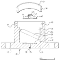
- a pyrotechnic device in accordance with the invention consists of a receptacle 1 formed from a hollow housing 2 and a closure 3 are moulded from an appropriate plastics material, which is preferably flame retardant.
- the receptacle 1 is adapted to contain a charge of pyrotechnic material schematically illustrated at 4, and a fuse 5 to ignite the pyrotechnical material.
- the housing 2 as can be seen in Figures 1, 2 and 3, consists of an integral moulding of the plastics material and has a tubular portion 6 comprising a cylindrical wall defining one open end 7.
- the open end 7 is provided with an internal recess in which is provided a circumferated screw thread 8.
- the other end of the tubular portion 6 extends to form a transverse wall in the form of a dome 9 which effectively closes that end of the tube.
- the material forming the dome 9 is thinner than the material forming the portion 6, and the thickness of the material reduces towards the apex of the dome.
- the wall thickness of the tubular portion 6, as indicated at the point a is 1.78 millimetres
- the wall forming part of the dome as indicated at the point b is 0.51 millimetres thick and at the point c , towards the apex of the dome is 0.13 millimetres thick.
- the dome 9 is provided with eight channels 10 formed therein which each extend linearly from the apex of the dome 11, to the end of the tubular portion 6, the channels 10 being equi-angularly spaced.
- the channels can be considered to extend radially outwardly from a single point at the apex of the dome.
- Each channel has a width of 0.13 millimetres and the material thickness defining the base of the channel is 0.13 millimetres.
- the channels are formed on the exterior of the dome but may, in an alternative embodiment of the invention, be formed on the interior of the dome 9.
- the thin region at the apex of the dome and channels form lines of relative mechanical weakness, with regard to the thicker, and thus stronger, material forming the rest of the dome, for a purpose that will be explained more fully hereinafter.
- the closure 3 for the housing 2 comprises a disc 12 which has, at its outer periphery, a screw-thread 13 adapted to co-operate with the screw-thread 8 provided at the open end 7 of the tubular portion 6 of the housing 2.
- the lower surface of the disc (in the orientation shown) has a central planar circular region 15, and the disc then tapers radially outwardly to the periphery thereof.
- the thickness of the dis 12 at the periphery thereof is equal to the thickness of the wall of the tubular portion 6.
- an aperture 16 is provided leading to the hollow interior 17 of a boss 18 that extends upwardly from the top of the disc, in the orientation shown in the drawings.
- the lower part of the boss 18, adjacent the disc 12, is enlarged to form a shoulder 19.
- a radially extending bore 20 is provided extending from the hollow interior 17 of the boss 18 to the exterior of the shoulder 19.
- a recess 22 is provided which forms a terminal enlargement of the hollow interior 17 of the boss 18.
- the fuse 5 is an electric fuse which has two insulated wires 23,24 extending therefrom. These wires would be cut to an appropriate length and the ends of the wires would be bared 25,26.
- the fuse 5 contains a wire or element which becomes hot when an electric current passes through it, surrounded by an ignition pill or the like, so that when a current passes through the fuse, the fuse ignites.
- An annular contact ring 27 of metal, such as brass or the like, is provided dimensioned to be a friction fit on the shoulder 19, and a dish-shaped metallic contact disc 28, again of brass or the like, is provided adapted to be a snap-fit within the recess 22 provided at the end of the boss 18.
- the two wires 23,24 of the fuse 5 are cut to an appropriate length and have the end portions thereof bared 25,26.
- the wires 23,24 are then passed upwardly through the central aperture 16 formed in the disc 12 of the closure 3.
- the wire 24 is threaded through the bore 20 so that the bare end 26 of the wire emerges from the end of the bore 20.
- the other wire 23 has the bare portion thereof located to pass over the recess 22.
- the contact ring 27 may then be slid into position on the collar 19 trapping the bare end of the wire 26 between the ring 27 and the collar 19, thus establishing contact between the wire 24 and the ring 27.
- the dish-shaped contact element 28 may be snapped into position trapping the bare part of the wire 25 between the edge of the dish-shaped element 28 and the recess 22.
- electrical contact is established between the wire 23 and the dish-shaped element 28.
- the fuse 5 may be held in position against the convex under surface 15 of the disc 12 by means of a hot-melt 29 although a quick setting adhesive could be used. The hot melt or the adhesive seals the aperture 16.
- the charge of pyrotechnic material 4 is then inserted into the housing 2, and the closure 3 is screwed into position on the housing 2.
- the closure 3 is screwed tight so that the receptacle 1 is sealed.
- the joint between the closure and the housing may additionally be sealed with adhesive, or with a welding step, or be bonded in some other way - for example, ultrasonic bonding. This prevents the contents of several devices being amalgamated to provide an enhanced effect.
- the receptacle 1 Since the receptacle 1 is totally sealed, and since the receptacle is made of a material that is impermeable to water and water vapour, there is no way that moisture can gain access to the pyrotechnic material 4 within the receptacle 1. Also, since the receptacle 1 is fabricated from a plastics material, and since the receptacle does not have protruding pins, the risk of the receptacle being punctured or otherwise broken in an inadvertent manner, either while packed, or while being inserted into a socket is significantly reduced.
- the housing When a pyrotechnic device as described with reference to Figures 1 to 3 is to be utilised, the housing will be inverted, so that the projecting boss 18 is located on the under-side of the arrangement.
- the closure 3 thus forms the lower wall of the closed receptacle, and the dome 9 forms the upper wall.
- the boss 18 may then be inserted into an appropriate screw-threaded socket 30 (which is similar to an "Edison" socket) and by rotating the housing the boss 18 will be screwed into the socket. Because the device is screwed in, it is easier to locate in the socket in the dark or under difficult conditions on stage, and there is less chance of a spark being generated.
- the socket 30 comprises a first element 31 integrally moulded of a plastics material and presenting a substantially planar base 32 provided with apertures 33 in a peripheral portion thereof to enable the base to be secured to an underlying support by means of screws or bolts.
- a first element 31 integrally moulded of a plastics material and presenting a substantially planar base 32 provided with apertures 33 in a peripheral portion thereof to enable the base to be secured to an underlying support by means of screws or bolts.
- an upstanding tubular boss 34 which is substantially hollow, with an open top.
- a bore 35 extends through the base into the hollow interior 36 of the boss 34, and terminates in a large open topped recess 37 formed in the base 32.
- a arcuate section channel 38 extends across the underside of the base 32 from the bottom of the bore 35 to the periphery of the base 32 for a purpose that will be explained hereinafter.
- a screw-threading arrangement 39 dimensioned and designed to co-operate with the helical ribs 21 forming the screw-thread described above.
- the arrangement 39 comprises ribs formed on the interior wall of the boss, but in an alternative embodiment may comprise helical grooves to receive the ribs 21.
- the upper part of the hollow interior 36 of the boss 34 comprises a radially enlarged recess 40 which is associated with a radially extending bore 41 which extends through the wall of the boss 34.
- a first contact element 42 is provided in the form of a plate 43 adapted to be received within the recess 37 as a friction fit, the plate 43, carrying on its upper surface a centrally located compression spring 44 which extends upwardly and supports a contact disc 45 formed of an appropriate metal. Soldered to the bottom of the plate 43 is the bare end of a wire which is passed upwardly through the bore 35, the wire being accommodated in the recess 38 when the base 32 is secured to an underlying support.
- a second contact element in the form of a contact ring 46 is provided, adapted to fit as a friction fit within the recess 40.
- a wire may have a bare end thereof passed through the bore 41, the bare end being soldered to the contact ring 46 when the contact ring 46 is inserted into the recess 40.
- the contact ring 46 presents a tapering inner face 47.
- the contact ring 46 is formed of a hard metal, such as hardened steel.
- the boss 18 of the pyrotechnic device When the boss 18 of the pyrotechnic device is inserted into the socket 30, as described, from above, the boss 18 is inserted into the hollow interior 36 of the boss 34.
- the ribs 21 engage and co-operate with the ribs 39, drawing the boss 18 into the hollow interior 36 of the boss 34.
- the dish-shaped element 28 engages the contact disc 45 and moves the contact disc 45 downwardly against the bias of the spring 44.
- the exposed corner of the contact ring 27 engages the tapering face 47 of the contact ring 46.
- the device is thus secured in the socket and electrical contact is established between the wires associated with the socket and the two contact elements provided on the pyrotechnic device.
- the socket is thus adapted to establish electric contact with the ring 27 and the dish-shaped element 28, to enable an electric circuit to be completed to enable a current to be passed through the fuse 5. Because the receptacle had been inverted the pyrotechnic material will be in contact with the fuse, and will thus be ignited when the fuse ignites.
- the pyrotechnic material When the pyrotechnic material is ignited, the pressure within the receptacle 1 rises, and the receptacle bursts, initially along the area and lines of relative mechanical weakness constituted by the thin area at the apex of the dome and by the material forming the channels 10. Typically, the dome then opens, like the petals of a flower, and the device provides the desired pyrotechnic effect.
- the receptacle can open with no parts or fragments becoming separated from the main part of the receptacle.
- the described pattern of lnes of relative mechanical weakness which extend radially outwardly from a point provides substantially triangular areas of strong material which lie between the weak lines, and these "triangles" are deflected by the pressure within the receptacle to "open" the receptacle.
- the effect provided by the device depends upon the precise nature of the pyrotechnic material introduced into the receptacle 1.
- the device may be a flash or a smoke effect or any other desired effect.
- the closure 3 is connected to the housing 2 by means of a screw-threaded arrangement
- the closure 3 may be connected to the housing 2 in some other way, for example by means of an adhesive or by means of sonic welding, or by means of a hot melt.
- the configuration of the lines of weakness provided on the receptacle may take many forms and indeed, instead of lines of weakness as constituted by the channels, a relatively large area of mechanical weakness may be defined by a thin web. It is, however, preferred to use lines of mechanical weakness since this can provide the desired "burstablity" when the device is ignited, whilst still giving a strong receptacle that will not easily be punctured or damaged during transit.
- the area of the receptacle provided with the lines of mechanical weakness is shown as being of a dome configuration, this is not essential and this part of the receptacle may take any desired form.
Landscapes
- Engineering & Computer Science (AREA)
- General Engineering & Computer Science (AREA)
- Manufacturing & Machinery (AREA)
- Fuses (AREA)
- Air Bags (AREA)
- Materials For Medical Uses (AREA)
- Details Of Connecting Devices For Male And Female Coupling (AREA)
- Feeding, Discharge, Calcimining, Fusing, And Gas-Generation Devices (AREA)
Claims (9)
- Pyrotechnische Vorrichtung mit einem Behälter (1), wobei der Behälter eine Ladung (4) eines pyrotechnischen Materials enthält, und mit Mitteln (5) zum Zünden der Ladung, wobei der Behälter abgedichtet ist, dadurch gekennzeichnet, daß der Behälter einen Teilabschnitt (9) aufweist, der ein Formteil umfaßt, das mechanisch verhältnismäßig schwache Bahnen oder Bereiche (10) aufweist, die so beschaffen sind, daß sie durch Aktivierung des pyrotechnischen Materials zerreißen, wobei die mechanisch schwachen Bahnen oder Bereiche eine Vielzahl verhältnismäßig dünner Gewebe (10) enthalten, die in einer Wand des Formteils gebildet sind.
- Vorrichtung nach Anspruch 1, dadurch gekennzeichnet, daß der Teilabschnitt (9) in Form einer Kuppel gebildet ist, und daß sich die mechanische Schwachstellen bildenden Bahnen (10) von dem Scheitelpunkt der Kuppel linear nach außen erstrecken.
- Vorrichtung nach einem oder mehreren der vorhergehenden Ansprüche, dadurch gekennzeichnet, daß der Behälter aus einem Gehäuse (2), das eine Öffnung festlegt, und einem Verschluß (3) gebildet ist, der zum Andichten der Öffnung mit dem Gehäuse verbunden ist, wobei das Gehäuse und der Verschluß jeweils aus einem Kunststoff geformt sind.
- Vorrichtung nach einem oder mehreren der vorhergehenden Ansprüche, dadurch gekennzeichnet, daß die Mittel (5) zum Zünden der Ladung eines pyrotechnischen Materials (4) einen Zünder umfassen, der so beschaffen ist, daß die Ladung gezündet wird, wenn ein elektrischer Stromfluß durch den Zünder hindurchgeführt wird, wobei der Behälter (2) einen vorstehenden Abschnitt (18) aufweist, welcher ein Schraubengewinde (21) zum Eingriff in einen entsprechenden Sockel besitzt, wobei der vorstehende Abschnitt zwei getrennte elektrische Kontakte (27, 28) besitzt, welche elektrisch mit dem Zünder (8) verbunden sind, so daß ein elektrischer Stromfluß von dem Sockel durch den Zünder zum Zünden der Vorrichtung hindurchgeführt werden kann, wenn der mit einem Gewinde versehene vorstehende Abschnitt in einen zugehörigen, entsprechenden Sockel geschraubt wird.
- Pyrotechnische Vorrichtung nach Anspruch 4, dadurch gekennzeichnet, daß der vorstehende Abschnitt (18) integral aus Kunststoff geformt ist und ein Schraubengewinde (21) umreißt, wobei der vorstehende Abschnitt zwei getrennte metallische Kontakte (27, 28) aufweist, welche in elektrischer Verbindung mit dem Zünder sind.
- Pyrotechnische Vorrichtung mit einem zweiteiligen Behälter (2, 3) dadurch gekennzeichnet, daß die zwei Teile (2, 3) jeweils aus einem Kunststoff geformt sind und zur hermetischen Abdichtung des Behälters aneinander befestigt sind, wobei der Behälter ein pyrotechnisches Material (4) und einen Zünder zum Zünden des pyrotechnischen Materials enthält, wobei ein vorstehender Abschnitt (18) mit einem der Teile (3) integral geformt ist, und der Abschnitt ein Schraubengewinde umreißt und zwei getrennte metallische Kontakte (27, 28) aufweist, welche in elektrischer Verbindung mit dem Zünder sind.
- Vorrichtung nach Anspruch 5 oder 6, dadurch gekennzeichnet, daß ein elektrischer Kontakt einen ringförmigen Kontakt (27) enthält, der den Boden des vorstehenden Abschnittes umgibt und mit einem Draht (24), der mit dem Zünder (5) verbunden ist, in Eingriff steht, wobei der zweite Kontakt ein Element (28) enthält, das in einer Aussparung an dem Ende des vorstehenden Abschnittes (18) aufgenommen ist und wiederum in Verbindung mit einem Draht (23) steht, welcher zu dem Zünder (5) führt.
- Ein Verfahren zur Herstellung einer pyrotechnischen Vorrichtung, dadurch gekennzeichnet, daß das Verfahren die Schritte umfaßt, daß zwei Bestandteile (2, 3) aus Kunststoff geformt werden, welche zur Bildung eines geschlossenen Behälters zusammengebaut werden können, wobei wenigstens einer der Bestandteile eine oder mehrere Bahnen (10) aufweist, die mechanische Schwachstellen bilden und unter einem aufgebrachten Druck zerrissen werden können, und jede, eine mechanische Schwachstelle bildende Bahn ein verhältnismäßig dünnes Gewebe in der Wand des Formteils enthält, wobei einer der Bestandteile mit einem Zünder (5) und elektrischen Kontaktmitteln (27, 28), die elektrisch mit dem Zünder verbunden sind, ausgestattet ist, und die Kontaktmittel so beschaffen sind, daß sie an der Außenseite des Behälters liegen; daß eine Ladung eines pyrotechnischen Materials (4) in den Behälter eingebracht wird, und daß die beiden Bestandteile des Behälters zur Bildung eines dichten Behälters, der den Zünder und das pyrotechnische Material enthält, zusammengebaut werden.
- Verfahren nach Anspruch 8, dadurch gekennzeichnet, daß das Verfahren die Schritte umfaßt, daß Abschnitte der sich vom Zünder erstreckenden Kontaktdrähte (23, 24) enthüllt werden, die unverhüllten Enden der Drähte in vorbestimmten Positionen auf dem mit einem Schraubengewinde versehenen Vorsprung untergebracht werden, und die Kontaktmittel (27, 28) an dem Vorsprung befestigt werden, um die unverhüllten Drähte in Eingriff zu nehmen und anzuschließen.
Applications Claiming Priority (2)
| Application Number | Priority Date | Filing Date | Title |
|---|---|---|---|
| GB909011559A GB9011559D0 (en) | 1990-05-23 | 1990-05-23 | Improvements in or relating to a pyrotechnic device |
| GB9011559 | 1990-05-23 |
Publications (2)
| Publication Number | Publication Date |
|---|---|
| EP0458074A1 EP0458074A1 (de) | 1991-11-27 |
| EP0458074B1 true EP0458074B1 (de) | 1995-02-08 |
Family
ID=10676438
Family Applications (1)
| Application Number | Title | Priority Date | Filing Date |
|---|---|---|---|
| EP91106460A Expired - Lifetime EP0458074B1 (de) | 1990-05-23 | 1991-04-22 | Pyrotechnische Vorrichtung |
Country Status (6)
| Country | Link |
|---|---|
| US (2) | US5313887A (de) |
| EP (1) | EP0458074B1 (de) |
| AT (1) | ATE118273T1 (de) |
| DE (1) | DE69107236T2 (de) |
| ES (1) | ES2067788T3 (de) |
| GB (1) | GB9011559D0 (de) |
Families Citing this family (15)
| Publication number | Priority date | Publication date | Assignee | Title |
|---|---|---|---|---|
| US5427031A (en) * | 1993-05-20 | 1995-06-27 | Ici Explosives Usa Inc. | Detonator primer capsule |
| US5648634A (en) | 1993-10-20 | 1997-07-15 | Quantic Industries, Inc. | Electrical initiator |
| US5728964A (en) * | 1993-10-20 | 1998-03-17 | Quantic Industries, Inc. | Electrical initiator |
| ES2173775B1 (es) * | 1999-10-21 | 2003-12-16 | Gomez Miguel Angel Dolcet | Carcasa para pirotecnia. |
| DE102005009644B4 (de) * | 2005-03-03 | 2013-09-12 | Schott Ag | Zündvorrichtung für eine pyrotechnische Schutzvorrichtung, Verfahren zur Herstellung einer solchen Zündvorrichtung sowie Gasgenerator mit einer solchen Zündvorrichtung |
| US7472758B1 (en) * | 2005-07-11 | 2009-01-06 | Williams-Pyro, Inc. | Initiator for stovetop fire extinguisher |
| US7886667B1 (en) * | 2008-10-15 | 2011-02-15 | The United States Of America As Represented By The Secretary Of The Army | More safe insensitive munition for producing a controlled fragmentation pattern |
| US20110297402A1 (en) * | 2010-06-03 | 2011-12-08 | Cesar Belmonte | Fire-Suppressing Ceiling Panels |
| FR2979984B1 (fr) * | 2011-09-12 | 2019-04-05 | Far Ouest | Petard pyrotechnique |
| US9597534B1 (en) | 2013-08-12 | 2017-03-21 | Williamsrdm, Inc. | Stovetop fire suppressor initiator device and method |
| US9636530B2 (en) | 2014-02-21 | 2017-05-02 | Williamsrdm, Inc. | Stovetop fire suppressor with thermal glass bulb actuation and method |
| US9517370B2 (en) * | 2014-02-21 | 2016-12-13 | Williamsrdm, Inc. | Distribution of fire suppressing agent in a stovetop fire suppressor and method |
| US10478647B2 (en) | 2014-11-27 | 2019-11-19 | Williams Rdm, Inc | Stovetop fire suppressor with shuttle actuator and method |
| US9759533B2 (en) | 2015-03-02 | 2017-09-12 | Nostromo Holdings, Llc | Low collateral damage bi-modal warhead assembly |
| US10232202B1 (en) * | 2016-09-07 | 2019-03-19 | WilliamsRDM, Inc | Self contained stovetop fire suppressor with alert signal and method |
Family Cites Families (25)
| Publication number | Priority date | Publication date | Assignee | Title |
|---|---|---|---|---|
| US1303727A (en) * | 1919-05-13 | Process fob making shrapnel-shells | ||
| US174771A (en) * | 1876-03-14 | buoadwell | ||
| US1562552A (en) * | 1923-02-09 | 1925-11-24 | Frank H Hanley | Electric-iron plug |
| US2724736A (en) * | 1953-02-27 | 1955-11-22 | Jr Ferdinand Klumpp | Spring type strain-relief bushing |
| US3491694A (en) * | 1954-06-08 | 1970-01-27 | Us Navy | Plastic liners for controlled fragmentation |
| US3420173A (en) * | 1967-03-31 | 1969-01-07 | Atlas Chem Ind | Axially expandable and contractable container |
| FR1551889A (de) * | 1967-07-13 | 1969-01-03 | ||
| US3580173A (en) * | 1968-04-04 | 1971-05-25 | Machet Ets | Explosive table decoration |
| US3474389A (en) * | 1968-04-12 | 1969-10-21 | Hideo Nagano | Electric connector |
| DE1807527A1 (de) * | 1968-11-07 | 1971-02-11 | Rheinmetall Gmbh | Knalldarstellungsmunition |
| US3646845A (en) * | 1969-07-17 | 1972-03-07 | Bernard J Semel | Method of making practical joke smoke-emitting articles |
| US3853059A (en) * | 1971-01-11 | 1974-12-10 | Us Navy | Configured blast fragmentation warhead |
| US3820464A (en) * | 1973-03-09 | 1974-06-28 | Us Navy | Variable sized fragment explosive projectile |
| DE2327947A1 (de) * | 1973-06-01 | 1974-12-19 | Dynamit Nobel Ag | Feuerwerkskoerper |
| FR2298782A1 (fr) * | 1975-01-24 | 1976-08-20 | Gruaz Eric | Procede et dispositif pour la fermeture de l'extremite o |
| US4351239A (en) * | 1975-02-28 | 1982-09-28 | The United States Of America As Represented By The Secretary Of The Navy | Warhead, incendiary |
| US5040464A (en) * | 1977-05-31 | 1991-08-20 | The United States Of America As Represented By The Secretary Of The Navy | Controlled fragmentation with fragment mix |
| GB1580579A (en) * | 1977-07-06 | 1980-12-03 | Wilson R | Pyrotechnic devices |
| CA1097912A (en) * | 1978-07-04 | 1981-03-24 | Walter J. Fenrick | Modified ground burst chemical simulator |
| US4173384A (en) * | 1978-08-23 | 1979-11-06 | The United States Of America As Represented By The Secretary Of The Navy | Flexible co-axial connector for cable in-line electronics |
| ES476388A1 (es) * | 1978-12-27 | 1979-04-16 | Lasheras Barrios Fernando | Mejoras introducidas en la fabricacion de proyectiles. |
| DE7925652U1 (de) * | 1979-09-11 | 1981-03-19 | Ets. Salgad, Vaduz | Fluegelstabilisiertes geschoss |
| US4433625A (en) * | 1982-01-11 | 1984-02-28 | Mar-Kay Plastics, Inc. | Blow molded dynamite tube |
| EP0312491A1 (de) * | 1987-10-14 | 1989-04-19 | Karl Merz | Splittermantel für metalische Explosivkörper sowie Verfahren zu seiner Herstellung |
| US4942820A (en) * | 1988-11-14 | 1990-07-24 | Sawruk Stephen D | Fragmentation device |
-
1990
- 1990-05-23 GB GB909011559A patent/GB9011559D0/en active Pending
-
1991
- 1991-04-22 ES ES91106460T patent/ES2067788T3/es not_active Expired - Lifetime
- 1991-04-22 AT AT91106460T patent/ATE118273T1/de active
- 1991-04-22 EP EP91106460A patent/EP0458074B1/de not_active Expired - Lifetime
- 1991-04-22 DE DE69107236T patent/DE69107236T2/de not_active Expired - Fee Related
- 1991-05-23 US US07/704,039 patent/US5313887A/en not_active Expired - Fee Related
-
1993
- 1993-04-26 US US08/052,762 patent/US5375523A/en not_active Expired - Fee Related
Also Published As
| Publication number | Publication date |
|---|---|
| ATE118273T1 (de) | 1995-02-15 |
| DE69107236D1 (de) | 1995-03-23 |
| US5313887A (en) | 1994-05-24 |
| US5375523A (en) | 1994-12-27 |
| EP0458074A1 (de) | 1991-11-27 |
| DE69107236T2 (de) | 1995-05-24 |
| GB9011559D0 (en) | 1990-07-11 |
| ES2067788T3 (es) | 1995-04-01 |
Similar Documents
| Publication | Publication Date | Title |
|---|---|---|
| EP0458074B1 (de) | Pyrotechnische Vorrichtung | |
| US5178547A (en) | Initiator assembly with connector interface element | |
| US5853912A (en) | Lithium ion electrochemical cell with safety valve electrical disconnect | |
| US1933694A (en) | Electrically controlled actuating device | |
| US5677076A (en) | Safety device for enclosed cell | |
| US5733135A (en) | Air bag inflator assembly with shorting clip | |
| US4191806A (en) | Pressure vent for a sealed primary cell | |
| CA2156363C (en) | Air bag inflator with pressure sensor | |
| US4338382A (en) | Battery safety terminal | |
| JP2005166652A (ja) | 特に高電流強さ用電気回路の分離装置 | |
| US5876868A (en) | Battery sealing structure | |
| US4384267A (en) | Thermosensitive fuse | |
| EP0798793A2 (de) | Batterie mit Membransicherheitsventil | |
| US6257910B1 (en) | Shorting clip for air bag inflator | |
| US4278637A (en) | Chemical oxygen generator | |
| JPS5831727B2 (ja) | 過圧安全装置を具える巻形コンデンサ | |
| US4385216A (en) | Circuit breaker devices with a pyrotechnically destructible conductor having a fuse system in parallel | |
| US4130060A (en) | Pyrotechnic devices | |
| US3964390A (en) | Bursting disc assembly | |
| JP6710167B2 (ja) | ガス発生器 | |
| US3973498A (en) | Initiation device for explosive charge | |
| MXPA96005958A (en) | Apparatus to inflate a bag of a | |
| US4809136A (en) | Condenser with a securing ring | |
| US4609973A (en) | Metallized plastic film electric capacitor | |
| CA2191791A1 (en) | Apparatus for inflating an airbag |
Legal Events
| Date | Code | Title | Description |
|---|---|---|---|
| PUAI | Public reference made under article 153(3) epc to a published international application that has entered the european phase |
Free format text: ORIGINAL CODE: 0009012 |
|
| AK | Designated contracting states |
Kind code of ref document: A1 Designated state(s): AT BE CH DE DK ES FR GB GR IT LI LU NL SE |
|
| 17P | Request for examination filed |
Effective date: 19920311 |
|
| 17Q | First examination report despatched |
Effective date: 19940301 |
|
| GRAA | (expected) grant |
Free format text: ORIGINAL CODE: 0009210 |
|
| AK | Designated contracting states |
Kind code of ref document: B1 Designated state(s): AT BE CH DE DK ES FR GB GR IT LI LU NL SE |
|
| PG25 | Lapsed in a contracting state [announced via postgrant information from national office to epo] |
Ref country code: NL Effective date: 19950208 Ref country code: LI Effective date: 19950208 Ref country code: GR Free format text: LAPSE BECAUSE OF FAILURE TO SUBMIT A TRANSLATION OF THE DESCRIPTION OR TO PAY THE FEE WITHIN THE PRESCRIBED TIME-LIMIT Effective date: 19950208 Ref country code: DK Effective date: 19950208 Ref country code: CH Effective date: 19950208 Ref country code: AT Effective date: 19950208 |
|
| REF | Corresponds to: |
Ref document number: 118273 Country of ref document: AT Date of ref document: 19950215 Kind code of ref document: T |
|
| REF | Corresponds to: |
Ref document number: 69107236 Country of ref document: DE Date of ref document: 19950323 |
|
| REG | Reference to a national code |
Ref country code: ES Ref legal event code: FG2A Ref document number: 2067788 Country of ref document: ES Kind code of ref document: T3 |
|
| PG25 | Lapsed in a contracting state [announced via postgrant information from national office to epo] |
Ref country code: LU Free format text: LAPSE BECAUSE OF NON-PAYMENT OF DUE FEES Effective date: 19950430 |
|
| ITF | It: translation for a ep patent filed | ||
| PG25 | Lapsed in a contracting state [announced via postgrant information from national office to epo] |
Ref country code: SE Effective date: 19950508 |
|
| ET | Fr: translation filed | ||
| REG | Reference to a national code |
Ref country code: CH Ref legal event code: PL |
|
| NLV1 | Nl: lapsed or annulled due to failure to fulfill the requirements of art. 29p and 29m of the patents act | ||
| PLBE | No opposition filed within time limit |
Free format text: ORIGINAL CODE: 0009261 |
|
| STAA | Information on the status of an ep patent application or granted ep patent |
Free format text: STATUS: NO OPPOSITION FILED WITHIN TIME LIMIT |
|
| 26N | No opposition filed | ||
| PGFP | Annual fee paid to national office [announced via postgrant information from national office to epo] |
Ref country code: GB Payment date: 19960416 Year of fee payment: 6 |
|
| PGFP | Annual fee paid to national office [announced via postgrant information from national office to epo] |
Ref country code: FR Payment date: 19960424 Year of fee payment: 6 |
|
| PGFP | Annual fee paid to national office [announced via postgrant information from national office to epo] |
Ref country code: ES Payment date: 19960425 Year of fee payment: 6 |
|
| PGFP | Annual fee paid to national office [announced via postgrant information from national office to epo] |
Ref country code: DE Payment date: 19960429 Year of fee payment: 6 |
|
| PGFP | Annual fee paid to national office [announced via postgrant information from national office to epo] |
Ref country code: BE Payment date: 19960612 Year of fee payment: 6 |
|
| PG25 | Lapsed in a contracting state [announced via postgrant information from national office to epo] |
Ref country code: GB Effective date: 19970422 |
|
| PG25 | Lapsed in a contracting state [announced via postgrant information from national office to epo] |
Ref country code: ES Free format text: LAPSE BECAUSE OF NON-PAYMENT OF DUE FEES Effective date: 19970423 |
|
| PG25 | Lapsed in a contracting state [announced via postgrant information from national office to epo] |
Ref country code: BE Effective date: 19970430 |
|
| BERE | Be: lapsed |
Owner name: J E M SMOKE MACHINE CO. LTD Effective date: 19970430 |
|
| GBPC | Gb: european patent ceased through non-payment of renewal fee |
Effective date: 19970422 |
|
| PG25 | Lapsed in a contracting state [announced via postgrant information from national office to epo] |
Ref country code: FR Free format text: LAPSE BECAUSE OF NON-PAYMENT OF DUE FEES Effective date: 19971231 |
|
| PG25 | Lapsed in a contracting state [announced via postgrant information from national office to epo] |
Ref country code: DE Free format text: LAPSE BECAUSE OF NON-PAYMENT OF DUE FEES Effective date: 19980101 |
|
| REG | Reference to a national code |
Ref country code: FR Ref legal event code: ST |
|
| REG | Reference to a national code |
Ref country code: ES Ref legal event code: FD2A Effective date: 19990201 |
|
| PG25 | Lapsed in a contracting state [announced via postgrant information from national office to epo] |
Ref country code: IT Free format text: LAPSE BECAUSE OF NON-PAYMENT OF DUE FEES;WARNING: LAPSES OF ITALIAN PATENTS WITH EFFECTIVE DATE BEFORE 2007 MAY HAVE OCCURRED AT ANY TIME BEFORE 2007. THE CORRECT EFFECTIVE DATE MAY BE DIFFERENT FROM THE ONE RECORDED. Effective date: 20050422 |