EP0458183A2 - Verfahren zur verbesserten Bereitstellung von Behandlungsgas bei Wärmebehandlungen - Google Patents
Verfahren zur verbesserten Bereitstellung von Behandlungsgas bei Wärmebehandlungen Download PDFInfo
- Publication number
- EP0458183A2 EP0458183A2 EP91107868A EP91107868A EP0458183A2 EP 0458183 A2 EP0458183 A2 EP 0458183A2 EP 91107868 A EP91107868 A EP 91107868A EP 91107868 A EP91107868 A EP 91107868A EP 0458183 A2 EP0458183 A2 EP 0458183A2
- Authority
- EP
- European Patent Office
- Prior art keywords
- catalyst
- retort
- furnace
- treatment gas
- catalyst retort
- Prior art date
- Legal status (The legal status is an assumption and is not a legal conclusion. Google has not performed a legal analysis and makes no representation as to the accuracy of the status listed.)
- Granted
Links
- 238000011282 treatment Methods 0.000 title claims abstract description 36
- 238000010438 heat treatment Methods 0.000 title claims abstract description 28
- 238000000034 method Methods 0.000 title claims abstract description 13
- 239000007789 gas Substances 0.000 title description 44
- 239000003054 catalyst Substances 0.000 claims abstract description 69
- 238000005253 cladding Methods 0.000 claims description 20
- 239000000463 material Substances 0.000 claims description 8
- 238000006243 chemical reaction Methods 0.000 description 6
- 230000001681 protective effect Effects 0.000 description 3
- 238000012423 maintenance Methods 0.000 description 2
- VNWKTOKETHGBQD-UHFFFAOYSA-N methane Chemical compound C VNWKTOKETHGBQD-UHFFFAOYSA-N 0.000 description 2
- 239000000203 mixture Substances 0.000 description 2
- 238000000137 annealing Methods 0.000 description 1
- 238000011234 economic evaluation Methods 0.000 description 1
- 239000002737 fuel gas Substances 0.000 description 1
- 238000009413 insulation Methods 0.000 description 1
- 239000003345 natural gas Substances 0.000 description 1
Images
Classifications
-
- C—CHEMISTRY; METALLURGY
- C21—METALLURGY OF IRON
- C21D—MODIFYING THE PHYSICAL STRUCTURE OF FERROUS METALS; GENERAL DEVICES FOR HEAT TREATMENT OF FERROUS OR NON-FERROUS METALS OR ALLOYS; MAKING METAL MALLEABLE, e.g. BY DECARBURISATION OR TEMPERING
- C21D1/00—General methods or devices for heat treatment, e.g. annealing, hardening, quenching or tempering
- C21D1/74—Methods of treatment in inert gas, controlled atmosphere, vacuum or pulverulent material
- C21D1/76—Adjusting the composition of the atmosphere
- C21D1/763—Adjusting the composition of the atmosphere using a catalyst
Definitions
- the invention relates to a method for providing treatment gas in heat treatments, the treatment gas being generated in a catalyst retort which is arranged in an associated furnace and is at furnace temperature, and a corresponding device.
- the object of the present invention results from this background and consists in improving a method according to the preamble of claim 1 and known catalyst retorts so that the usability in the direction of lower operating temperatures in heat treatments is expanded.
- the catalyst retort which is to be arranged implicitly in the furnace is surrounded in the furnace by a shield, the treatment gas emerging from the catalyst retort being first introduced into the shield and only then being released into the furnace space.
- the catalyst retort is isolated from the gas atmosphere in the furnace interior by the fact that the freshly generated treatment gas is temporarily held in the shielded, enveloped catalyst retort.
- a higher degree of heating of the catalyst mass in the catalyst retort can be maintained even at furnace temperatures below 750 ° C., so that the complete conversion of the feed gas into the treatment gas remains guaranteed.
- the heating output can be set lower than without shielding.
- An advantageous embodiment of the invention for the frequently occurring tubular catalyst retorts derived from a radiant heater tube is that they are surrounded by a likewise essentially tubular shield (11) which surrounds the catalyst retort at a distance, the treatment gas before it is introduced into the interior of the furnace is routed as far as possible within the shield.
- a device according to the invention with an essentially tubular catalyst retort with jacket tube, heating, catalyst material and gas supply and discharge devices as well as gas outlet openings for the treatment gas generated is characterized in that with the substantially tubular actual catalyst retort, a cladding tube (11) or other profile which is selected in cross section is connected such that the catalyst retort is arranged approximately coaxially and centered in this cladding tube or profile this results in a free space (14) surrounding the catalyst retort, the cladding tube or profile being equipped with passage openings for the treatment gas trapped therein.
- a particularly advantageous embodiment is that the passage openings (15) are arranged in the cladding tube or profile in such a way that the flow path of the newly formed treatment gas in the cladding tube or profile is as long as possible.
- This configuration ensures that the treatment gas which is at a higher temperature level and which emerges freshly from the catalyst retort remains in the vicinity of the retort for as long as possible and is thus kept at a higher temperature level.
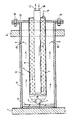
- the figure shows a device according to the invention installed between two walls 6, 7 of a heat treatment system, with a catalyst retort 1, internal heating 2 and a shielding cladding tube 11.
- the essentially tubular catalyst retort 1 is equipped with a feed line 8 for the feed gas, which, for example, consists of a mixture Natural gas and air can be.
- the internal volume of retort 1 is largely with Filled catalyst material 9, which ensures the conversion of the feed gas into the treatment gas.
- outlet openings 10 are provided for the converted gas.
- the feed gas passes through the catalyst material 9 located in the catalyst retort and exits the retort as treatment gas through the gas outlet openings 10.
- the internal heating 2 is arranged centrally in the catalyst retort, which can consist of a burner with fuel gas mixture supply 16 and exhaust gas line 17.
- the entire catalyst retort 1 is surrounded by the cladding tube 11 and is fastened coaxially and centered therein with a strut cross 12 and a flange 13. Because of the larger, cheap about 1.1 to twice the diameter of the cladding tube, there is a free space 14 between the catalyst retort and the cladding tube. Passage openings 15 are provided in the cladding tube 11 approximately at the opposite end to the end at which the gas outlet openings 10 are located on the retort itself. As a result, almost the entire length of the outside of the retort is only in contact with fresh, newly created, warmer treatment gas that flows in continuously.
- the sequence according to the invention is now as follows: If heat treatment is to be carried out at temperatures, for example around 750 ° C, under protective gas, e.g. an annealing treatment of metallic workpieces, whereby the heat treatment system can be a continuous furnace, then the problems described at the outset occur in a conventional design with the protective gas generation via catalyst retorts. incomplete conversion of the feed gas into treatment gas and risk of burning if the heating output is too high. Under Using the method according to the invention and the device, however, it is possible to provide treatment gas without problems.
- protective gas e.g. an annealing treatment of metallic workpieces
- a heating of the catalyst material in the retort is achieved at an approximately 10 to 20% higher level than if a catalyst retort were used without the jacket tube 11 essential to the invention.
- the natural gas-air feed gas flows through the feed line 8 in the cold state of the catalyst mass 9 and converts there after heating in, for example, CO / H2 / N2-containing treatment gas, which passes through the gas outlet openings 10 at the top of the catalyst retort 1 the cladding tube 11 flows into shielded free space 14.
- the treatment gas flows to the foot end of the catalyst retort in this shielded free space, since the through bores 15 of the cladding tube 11 are located there. Through this, the treatment gas finally enters the furnace interior. In this way, thermal insulation of the catalyst retort towards the furnace interior is achieved, as a result of which the above-mentioned increase in the temperature level in the catalyst retort and thus an objective essential to the invention is achieved.
- a further, additional advantage is that the procedure according to the invention or the implementation of the invention in terms of the device results in the possibility that the replacement of a catalyst retort can be considerably simplified. If the device according to the invention is designed so that the cladding tube 11 is connected to the catalyst retort 1, for example on the flange 13 by a releasable screw connection 18, while the front end of the catalyst retort is only loosely lying on the support cross 12 in the cladding tube 11 is held, the catalyst retort can be replaced practically while the treatment furnace is in operation, since the cladding tube 11 remains in the furnace and the latter is therefore still essentially closed. Thus, the catalyst retort is very easy to replace when the furnace is heated, which reduces costs for this type of operation.
- the method according to the invention thus provides an expansion of the possible uses of treatment gas generation with catalyst retorts, which can be desired and advantageous in a number of practical cases, with additional progress being made with regard to the maintenance and repair friendliness of a heat treatment system.
Landscapes
- Chemical & Material Sciences (AREA)
- Engineering & Computer Science (AREA)
- Chemical Kinetics & Catalysis (AREA)
- Physics & Mathematics (AREA)
- Thermal Sciences (AREA)
- Crystallography & Structural Chemistry (AREA)
- Mechanical Engineering (AREA)
- Materials Engineering (AREA)
- Metallurgy (AREA)
- Organic Chemistry (AREA)
- Furnace Details (AREA)
- Feeding, Discharge, Calcimining, Fusing, And Gas-Generation Devices (AREA)
- Catalysts (AREA)
- Muffle Furnaces And Rotary Kilns (AREA)
- Control Of Heat Treatment Processes (AREA)
- Tunnel Furnaces (AREA)
- Crucibles And Fluidized-Bed Furnaces (AREA)
- Air Bags (AREA)
- Heat Treatments In General, Especially Conveying And Cooling (AREA)
- Processing And Handling Of Plastics And Other Materials For Molding In General (AREA)
- Yarns And Mechanical Finishing Of Yarns Or Ropes (AREA)
- Heat Treatment Of Strip Materials And Filament Materials (AREA)
- Solid-Sorbent Or Filter-Aiding Compositions (AREA)
- Polymers With Sulfur, Phosphorus Or Metals In The Main Chain (AREA)
Abstract
Description
- Die Erfindung betrifft ein verfahren zur Bereitstellung von Behandlungsgas bei Wärmebehandlungen, wobei das Behandlungsgas in einer in einem zugehörigen Ofen angeordneten, unter Ofentemperatur stehenden Katalysatorretorte erzeugt wird sowie eine entsprechende Vorrichtung.
- Es sind eine Mehrzahl von Wärmebehandlungsverfahren und dabei insbesondere Wärmebehandlungen für metallische Werkstücke bekannt, die mit einer in den heißen Bereichen eines Wärmebehandlungsofens untergebrachten Katalysatorretorte zur Behandlungsgaserzeugung (Schutz oder Reaktionsgase) arbeiten (siehe z.B. DE-OS 36 30 833). Diesen Retorten wird im Betrieb ein Einsatzgas zugeführt, daß sich in diesen aufgrund des dort befindlichen Katalysators und des vorhandenen Temperaturniveaus aus der Ofenumgebung in das gewünschte Behandlungsgas umsetzt. Das dabei im Katalysatormaterial der Retorte sich bildende Behandlungsgas fließt dann direkt aus der Retorte in den Ofeninnenraum. Bei Wärmebehandlungen mit Temperaturen unter 800 °C Umgebungstemperatur für die Kataylsatorretorte beginnen jedoch aufgrund des relativ niedrigen Temperaturniveaus Probleme bei der vollständigen Umsetzung des Einsatzgases. Diese lassen sich bei selbstbeheizten Katalysatorretorten durch Erhöhung der Leistung eines innenseitig und benachbart zum Katalysatormaterial angeordneten Brenners in einem gewissen Rahmen wieder beheben. Ab einer gewissen unteren Grenztemperatur, ca. 750 °C, wird jedoch die Durchwärmung der Katalysatormasse wegen eines zu großen Wärmeabflusses an den "zu kalten" Ofenraum ungenügend, wobei dann wiederum eine nicht mehr ausreichende Umsetzung des Einsatzgases im Behandlungsgas die Folge ist. Andererseits ist bei weiterer Erhöhung der Beheizungsleistung die Gefahr des Durchbrennens der Katalysatorretorte gegeben, die in der Regel als Rohr mit außenseitig angeordneten Katalysatormaterial und innenseitigem Beheizungsbrenner ausgebildet ist. Derartige rohrförmige, mit einer Eigenbeheizung ausgestattete Katalysatorretorten sind z.B. der DE-OS 27 58 024 oder DE-OS 36 32 577 zu entnehmen.
- Bei solchen Katalysatorretorten besteht darüber hinaus das Problem, daß im Falle der Notwendigkeit einer Auswechslung eine vorübergehende Ofenabschaltung erfolgen muß.
- Die Aufgabenstellung der vorliegenden Erfindung ergibt sich aus diesem Hintergrund und besteht darin, ein Verfahren gemäß dem Oberbegriff des Anspruchs 1 sowie bekannte Katalysatorretorten so zu verbessern, daß die Einsetzbarkeit in Richtung niedrigerer Betriebstemperaturen bei Wärmebehandlungen erweitert wird.
- Diese Aufgabe wird dadurch gelöst, daß die verfahrensimplizit im Ofen anzuordnende Katalysatorretorte im Ofen von einer Abschirmung umgeben wird, wobei das aus der Katalysatorretorte austretende Behandlungsgas zuerst in die Abschirmung eingeleitet wird und erst dann in den Ofenraum entlassen wird.
- Mit dieser Maßnahme ergibt sich eine Isolierung der Katalysatorretorte gegenüber der im Ofeninnenraum befindlichen Gasatmosphäre, dadurch, daß das frisch entstandene Behandlungsgas in der abgeschirmten, eingehüllten Katalysatorretorte zwischenzeitlich gehalten wird. In der Folge kann auch bei Ofentemperaturen unter 750 °C eine höhere Durchwärmung der Katalysatormasse in der Katalysatorretorte aufrechterhalten werden, wodurch die vollständige Umsetzung des Einsatzgases in Behandlungsgas auch dann gewährleistet bleibt. Eine Durchbrenngefahr der Katalysatorretorte ist dabei ausgeschlossen, da die Beheizungsleistung geringer als ohne Abschirmung einzustellen ist.
- Eine vorteilhafte Ausgestaltung der Erfindung besteht für die häufig vorkommenden, rohrförmigen, von einem Beheizungsstrahlrohr abgeleiteten Katalysatorretorten darin, daß diese mit einer ebenfalls im wesentlichen rohrförmigen Abschirmung (11) umgeben werden, die die Katalysatorretorte mit einem Abstand umfaßt, wobei das Behandlungsgas vor seiner Einleitung in den Ofeninnenraum eine möglichst lange Strecke innerhalb der Abschirmung geführt wird.
- Eine Vorrichtung gemäß der Erfindung mit einer im wesentlichen rohrföhrmigen Katalysatorretorte mit Mantelrohr, Beheizung, Katalysatormaterial und Gaszufuhr- und -abfuhreinrichtungen sowie Gasaustrittsöffnungen für das erzeugte Behandlungsgas zeichnet sich dadurch aus, daß mit der im wesentlichen rohrföhrmigen eigentlichen Katalysatorretorte ein im Querschnitt so gewähltes Hüllrohr (11) oder sonstiges Profil verbunden ist, daß die Katalysatorretorte in diesem Hüllrohr oder Profil etwa koaxial und zentriert angeordnet ist und sich dabei ein die Katalysatorretorte umgebender Freiraum (14) ergibt, wobei das Hüllrohr oder Profil mit Durchtrittsöffnungen für das in ihr aufgefangene Behandlungsgas ausgestattet ist.
- Eine besonders vorteilhafte Ausgestaltung besteht darin, daß die Durchtrittsöffnungen (15) im Hüllrohr oder Profil so angeordnet sind, daß sich ein möglichst langer Strömungsweg des neu entstandenen Behandlungsgases im Hüllrohr oder Profil ergibt. Mit dieser Ausgestaltung wird erreicht, daß das auf einem höheren Temperaturniveau befindliche, frisch aus der Katalysatorretorte austretende Behandlungsgas möglichst lange in Retortennähe bleibt und diese somit auf einem höheren Temperaturniveau gehalten wird.
- Im folgenden soll die Erfindung anhand der schematischen Schnittfigur, die eine erfindungsgemäße Katalysatorretorte zeigt, beispielhaft näher beschrieben werden.
- Die Figur zeigt eine zwischen zwei Wände 6, 7 einer Wärmebehandlungsanlage installierte, erfindungsgemäße Einrichtung mit einer Katalysatorretorte 1, Innenbeheizung 2 und einem abschirmenden Hüllrohr 11. Die im wesentlichen rohrförmige Katalysatorretorte 1 ist mit einer Zuleitung 8 für das Einsatzgas ausgestattet, welches beispielsweise ein Gemisch aus Erdgas und Luft sein kann. Das Innenvolumen der Retorte 1 ist zu einem großen Teil mit Katalysatormaterial 9 gefüllt, das für die Umsetzung des zugeführten Einsatzgases in Behandlungsgas sorgt. An dem der Zuleitung 8 gegenüberliegenden Ende der Retorte 1 sind Austrittsöffnungen 10 für das umgesetzte Gas vorgesehen. Das Einsatzgas durchläuft im Betrieb das in der Katalysatorretorte befindliche Katalysatormaterial 9 und tritt als Behandlungsgas durch die Gasaustrittsöffnungen 10 wieder aus der Retorte aus. Die Innenbeheizung 2 ist zentral in der Katalysatorretorte angeordnet, wobei diese aus einem Brenner mit Brenngasgemischzufuhr 16 und Abgasleitung 17 bestehen kann. Die gesamte Katalysatorretorte 1 wird von dem Hüllrohr 11 umgeben und ist in diesem mit einem Strebenkreuz 12 und einem Flansch 13 koaxial und zentriert befestigt. Dabei ergibt sich aufgrund des größeren, günstig etwa 1.1 bis zweifachen Durchmessers des Hüllrohres ein Freiraum 14 zwischen Katalysatorretorte und Hüllrohr. Im Hüllrohr 11 sind etwa am entgegengesetzten Ende zu dem Ende, an dem sich die Gasaustrittöffnungen 10 an der Retorte selbst befinden, Durchtrittsöffnungen 15 angebracht. Dadurch steht die Außenseite der Retorte fast auf der gesamten Länge nur mit ständig neu zufließendem, frisch entstandenen, wärmeren Behandlungsgas in Berührung.
- Der erfindungsgemäße Ablauf ist nun wie folgt:
Ist eine Wärmebehandlung bei Temperaturen, beispielsweise um 750 °C unter Schutzgas durchzuführen, z.B. eine Glühbehandlung von metallischen Werkstücken, wobei es sich bei der Wärmebehandlungsanlage um einen Durchlaufofen handeln kann, so treten in konventioneller Ausführung mit der Schutzgaserzeugung über Katalysatorretorten die eingangs erläuterten Probleme auf - unvollständige Umsetzung des Einsatzgases in Behandlungsgas und Gefahr des Durchbrennens bei zu hoher Beheizungsleistung. Unter Anwendung des erfindungsgemäßen Verfahrens sowie der Vorrichtung ist jedoch eine problemlose Bereitstellung von Behandlungsgas möglich. Mit etwa gleichbleibender Heizleistung der Eigenbeheizung der Katalysatorretorte wird erfindungsgemäß nämlich eine Durchwärmung des Katalysatormaterials in der Retorte auf einem etwa 10 bis 20 % höheren Niveau erreicht, als wenn eine Katalysatorretorte ohne das erfindungswesentliche Hüllrohr 11 eingesetzt würde. Das Erdgas-Luft-Einsatzgas fließt über die Zuleitung 8 in kaltem Zustand der Katalysatormasse 9 zu und setzt sich dort nach Erwärmung in beispielsweise CO/H₂/N₂-haltiges Behandlungsgas um, das über die Gasaustrittsöffnungen 10 an der Spitze der Katalysatorretorte 1 in den durch das Hüllrohr 11 abgeschirmten Freiraum 14 einfließt. In diesem abgeschirmten Freiraum fließt das Behandlungsgas zum Fußende der Katalysatorretorte, da sich dort die Durchgangsbohrungen 15 des Hüllrohres 11 befinden. Durch diese tritt das Behandlungsgas schließlich in den Ofeninnenraum ein. Auf diese Weise wird eine Wärmeisolierung der Katalysatorretorte zum Ofeninnenraum hin erreicht, wodurch die obengenannte Erhöhung des Temperaturniveaus in der Katalysatorretorte und somit ein erfindungswesentliches Ziel erreicht ist. - Als weiterer, sich zusätzlich ergebender Vorteil erweist sich, daß sich bei der erfindungsgemäße Verfahrensweise bzw. bei der vorrichtungsmäßigen Realisierung der Erfindung die Möglichkeit ergibt, daß die Auswechslung einer Katalysatorretorte wesentlich vereinfacht werden kann. Wird nämlich die erfindungsgemäße Vorrichtung so gestaltet, daß das Hüllrohr 11 beispielsweise am Flansch 13 durch eine lösbare Schraubenverbindung 18 mit der Katalysatorretorte 1 verbunden ist, während das vordere Ende der Katalysatorretorte nur lose auf dem Stützkreuz 12 liegend im Hüllrohr 11 gehalten wird, so kann eine Auswechslung der Katalysatorretorte praktisch im laufenden Betrieb des Behandlungsofens erfolgen, da währenddessen das Hüllrohr 11 im Ofen verbleibt und dieser somit weiterhin im wesentlichen geschlossen ist. Somit ist die Katalysatorretorte auf sehr einfache Weise bei aufgeheiztem Ofen austauschbar, was Kostenaufwendungen für diesen Betriebsfall senkt.
- Neben der Hauptidee der Erfindung, nämlich quasi eine Isolierschicht zwischen einer in einem Ofen installierten Katalysatorretorte und dem Ofeninnenraum zu schaffen, ist diese Erhöhung der Wartungsfreundlichkeit einer Ofenanlage durch erfindungsgemäß gestaltete Katalysatorretorten ein wesentlicher Punkt im Hinblick auf die wirtschaftliche Bewertung der vorliegenden Erfindung.
- Das erfindungsgemäße Verfahren liefert also eine Erweiterung der Einsatzmöglichkeiten einer Behandlungsgaserzeugung mit Katalysatorretorten, die in einer Mehrzahl von praktischen Fällen erwünscht und vorteilhaft sein kann, wobei zusätzlich hinsichtlich der Wartungs- und Reparaturfreundlichkeit einer Wärmebehandlungsanlage wesentliche Fortschritte erzielt werden.
Claims (4)
- Verfahren zur Bereitstellung von Behandlungsgas bei Wärmebehandlungen, wobei das Behandlungsgas in einer in einem zugehörigen Ofen angeordneten, unter Ofentemperatur stehenden Katalysatorretorte erzeugt wird, dadurch gekennzeichnet, daß die Katalysatorretorte im Ofen von einer Abschirmung umgeben wird, wobei das in der Katalysatorretorte entstehende und aus dieser austretende Behandlungsgas zuerst in diese Abschirmung eingeleitet wird und erst darauf folgend aus dieser in den Ofenraum entlassen wird.
- Verfahren nach Anspruch 1, dadurch gekennzeichnet, daß bei einer im wesentlichen rohrförmigen Katalysatorretorte diese mit einer ebenfalls im wesentlichen rohrförmigen Abschirmung (11) umgeben wird, die die Katalysatorretorte mit einem Abstand umfaßt, wobei das Behandlungsgas vor seiner Einleitung in den Ofeninnenraum eine möglichst lange Strecke innerhalb der Abschirmung geführt wird.
- Vorrichtung zur Durchführung des Verfahrens nach einem oder mehreren der obigen Ansprüche mit einer im wesentlichen rohrföhrmigen Katalysatorretorte (1) mit Mantelrohr, Beheizung, Katalysatormaterial und Gaszufuhr- und -abfuhreinrichtungen sowie Gasaustrittsöffnungen für das erzeugtes Behandlungsgas dadurch gekennzeichnet,
daß mit der im wesentlichen rohrföhrmigen eigentlichen Katalysatorretorte ein im Querschnitt so gewähltes Hüllrohr (11) oder sonstiges Profil verbunden ist, daß die Katalysatorretorte in diesem Hüllrohr oder Profil etwa koaxial und zentriert angeordnet ist und sich dabei ein die Katalysatorretorte umgebender Freiraum (14) ergibt, wobei das Hüllrohr oder Profil mit Durchtrittsöffnungen (15) für das in ihr aufgefangene Behandlungsgas ausgestattet ist. - Verfahren nach Anspruch 3, dadurch gekennzeichnet, daß die Durchtrittsöffnungen (15) im Hüllrohr oder Profil so angeordnet sind, daß sich ein möglichst langer Strömungsweg des Behandlungsgases im Hüllrohr oder Profil ergibt.
Applications Claiming Priority (2)
| Application Number | Priority Date | Filing Date | Title |
|---|---|---|---|
| DE4016183 | 1990-05-19 | ||
| DE4016183A DE4016183A1 (de) | 1990-05-19 | 1990-05-19 | Verfahren zur verbesserten bereitstellung von behandlungsgas bei waermebehandlungen |
Publications (3)
| Publication Number | Publication Date |
|---|---|
| EP0458183A2 true EP0458183A2 (de) | 1991-11-27 |
| EP0458183A3 EP0458183A3 (en) | 1992-04-01 |
| EP0458183B1 EP0458183B1 (de) | 1994-12-07 |
Family
ID=6406799
Family Applications (1)
| Application Number | Title | Priority Date | Filing Date |
|---|---|---|---|
| EP91107868A Expired - Lifetime EP0458183B1 (de) | 1990-05-19 | 1991-05-15 | Verfahren zur verbesserten Bereitstellung von Behandlungsgas bei Wärmebehandlungen |
Country Status (9)
| Country | Link |
|---|---|
| US (1) | US5160380A (de) |
| EP (1) | EP0458183B1 (de) |
| AT (1) | ATE115192T1 (de) |
| BR (1) | BR9101982A (de) |
| CZ (1) | CZ285210B6 (de) |
| DE (2) | DE4016183A1 (de) |
| ES (1) | ES2067795T3 (de) |
| HU (1) | HU209813B (de) |
| ZA (1) | ZA913797B (de) |
Cited By (2)
| Publication number | Priority date | Publication date | Assignee | Title |
|---|---|---|---|---|
| EP0686701A1 (de) * | 1994-06-06 | 1995-12-13 | Praxair Technology, Inc. | Verfahren und Vorrichtung zum Herstellen von Wärmebehandlungsatmosphären |
| EP0860512A3 (de) * | 1997-02-25 | 1998-09-23 | Linde Aktiengesellschaft | Verfahren/Anlage zur Erzeugung von Behandlungsgas für die Wärmebehandlung metallischen Guts |
Families Citing this family (12)
| Publication number | Priority date | Publication date | Assignee | Title |
|---|---|---|---|---|
| US5221369A (en) * | 1991-07-08 | 1993-06-22 | Air Products And Chemicals, Inc. | In-situ generation of heat treating atmospheres using non-cryogenically produced nitrogen |
| US5417774A (en) * | 1992-12-22 | 1995-05-23 | Air Products And Chemicals, Inc. | Heat treating atmospheres |
| US5284526A (en) * | 1992-12-22 | 1994-02-08 | Air Products And Chemicals, Inc. | Integrated process for producing atmospheres suitable for heat treating from non-cryogenically generated nitrogen |
| US5298090A (en) * | 1992-12-22 | 1994-03-29 | Air Products And Chemicals, Inc. | Atmospheres for heat treating non-ferrous metals and alloys |
| US5348592A (en) * | 1993-02-01 | 1994-09-20 | Air Products And Chemicals, Inc. | Method of producing nitrogen-hydrogen atmospheres for metals processing |
| US5401339A (en) * | 1994-02-10 | 1995-03-28 | Air Products And Chemicals, Inc. | Atmospheres for decarburize annealing steels |
| US5968457A (en) * | 1994-06-06 | 1999-10-19 | Praxair Technology, Inc. | Apparatus for producing heat treatment atmospheres |
| US20070107818A1 (en) * | 2005-11-16 | 2007-05-17 | Bowe Donald J | Deoxygenation of furnaces with hydrogen-containing atmoshperes |
| US8689707B2 (en) * | 2006-05-26 | 2014-04-08 | Fuel Tech, Inc. | Ultra low NOx burner replacement system |
| US9157682B2 (en) | 2011-02-10 | 2015-10-13 | Linde Aktiengesellschaft | Furnace atmosphere generator |
| EP2806241A1 (de) | 2013-05-23 | 2014-11-26 | Linde Aktiengesellschaft | Verfahren zur Bereitstellung von Methanol für eine Wärmebehandlungsatmosphäre in einem Ofen |
| KR101701328B1 (ko) * | 2016-01-22 | 2017-02-13 | 한국에너지기술연구원 | Rx 가스 발생기 내장형 무산화 열처리 설비 |
Family Cites Families (10)
| Publication number | Priority date | Publication date | Assignee | Title |
|---|---|---|---|---|
| US3535074A (en) * | 1965-10-29 | 1970-10-20 | Hitachi Ltd | Method and apparatus for purifying crude inert gases |
| DE2420823A1 (de) * | 1974-04-30 | 1975-11-13 | Nassheuer Ind Ofenbau Jean | Strahlrohrbeheitzter waerm- bzw. gluehofen |
| DD131292A1 (de) * | 1977-03-28 | 1978-06-14 | Arnd Mueller | Einrichtung zur schutzgaserzeugung im ofenraum |
| US4398971A (en) * | 1981-12-31 | 1983-08-16 | Aga Aktiebolag | Method of heating, holding or heat treatment of metal material |
| FR2524006B1 (fr) * | 1982-03-23 | 1985-10-11 | Air Liquide | Procede de durcissement superficiel de pieces metalliques |
| US4417927A (en) * | 1982-03-29 | 1983-11-29 | General Electric Company | Steel nitriding method and apparatus |
| DE3302338A1 (de) * | 1983-01-25 | 1984-07-26 | Ruhrgas Ag, 4300 Essen | Verfahren zum haerten von metallwerkstuecken |
| DE3630833A1 (de) * | 1986-09-10 | 1988-03-17 | Linde Ag | Verfahren und vorrichtung zur waermebehandlung metallischer werkstuecke |
| DE3632577A1 (de) * | 1986-09-25 | 1988-05-05 | Linde Ag | Strahlrohrbrenner mit katalysatorbett fuer waermebehandlungsoefen |
| FR2649123B1 (fr) * | 1989-06-30 | 1991-09-13 | Air Liquide | Procede de traitement thermique de metaux |
-
1990
- 1990-05-19 DE DE4016183A patent/DE4016183A1/de not_active Withdrawn
-
1991
- 1991-05-15 BR BR919101982A patent/BR9101982A/pt unknown
- 1991-05-15 ES ES91107868T patent/ES2067795T3/es not_active Expired - Lifetime
- 1991-05-15 EP EP91107868A patent/EP0458183B1/de not_active Expired - Lifetime
- 1991-05-15 DE DE59103752T patent/DE59103752D1/de not_active Expired - Fee Related
- 1991-05-15 AT AT91107868T patent/ATE115192T1/de not_active IP Right Cessation
- 1991-05-16 CZ CS911449A patent/CZ285210B6/cs not_active IP Right Cessation
- 1991-05-17 HU HU911656A patent/HU209813B/hu not_active IP Right Cessation
- 1991-05-17 US US07/701,156 patent/US5160380A/en not_active Expired - Lifetime
- 1991-05-20 ZA ZA913797A patent/ZA913797B/xx unknown
Cited By (2)
| Publication number | Priority date | Publication date | Assignee | Title |
|---|---|---|---|---|
| EP0686701A1 (de) * | 1994-06-06 | 1995-12-13 | Praxair Technology, Inc. | Verfahren und Vorrichtung zum Herstellen von Wärmebehandlungsatmosphären |
| EP0860512A3 (de) * | 1997-02-25 | 1998-09-23 | Linde Aktiengesellschaft | Verfahren/Anlage zur Erzeugung von Behandlungsgas für die Wärmebehandlung metallischen Guts |
Also Published As
| Publication number | Publication date |
|---|---|
| CS144991A3 (en) | 1992-01-15 |
| HU209813B (en) | 1994-11-28 |
| BR9101982A (pt) | 1991-12-24 |
| ZA913797B (en) | 1992-02-26 |
| ES2067795T3 (es) | 1995-04-01 |
| CZ285210B6 (cs) | 1999-06-16 |
| ATE115192T1 (de) | 1994-12-15 |
| EP0458183A3 (en) | 1992-04-01 |
| HU911656D0 (en) | 1991-11-28 |
| EP0458183B1 (de) | 1994-12-07 |
| DE59103752D1 (de) | 1995-01-19 |
| DE4016183A1 (de) | 1991-11-21 |
| HUT61055A (en) | 1992-11-30 |
| US5160380A (en) | 1992-11-03 |
Similar Documents
| Publication | Publication Date | Title |
|---|---|---|
| EP0458183B1 (de) | Verfahren zur verbesserten Bereitstellung von Behandlungsgas bei Wärmebehandlungen | |
| DE2657529A1 (de) | Brenner fuer eine gasturbine | |
| DE3243395A1 (de) | Verfahren zum betrieb eines vergasungsbrenners | |
| DE1189221B (de) | Verfahren und Vorrichtung zur Herstellung von Russ | |
| DE102009053747A1 (de) | Verfahren zur Reduzierung von Stickoxiden aus dem Abgas eines Koksofens | |
| DE3346618A1 (de) | Verfahren zur erzeugung eines ueberhitzten hochdruckdampfes bei der kokstrockenkuehlung und geeignete vorrichtungen dazu | |
| EP0638514B1 (de) | Röhrenofen für die Erzeugung kohlenmonoxidhaltiger Gasgemische | |
| DE2639977C3 (de) | Verfahrem zum Schmelzen von Glas in einer brennerbeheizten Wanne und Glasschmelzofen zur Durchführung des Verfahrens | |
| DE2743030A1 (de) | Wirbelbettbrennkammer | |
| DE2812888C2 (de) | Isostatischer Heißpreßautoklav | |
| DE3200582C1 (de) | Verfahren zum Entfernen von Schmiermitteln von aus Metallpulver gepressten Formteilen und Vorrichtung zur Durchfuehrung des Verfahrens | |
| DE2541610C2 (de) | Verfahren zum Betreiben eines Winderhitzers | |
| EP0261462B1 (de) | Strahlrohrbrenner mit Katalysatorbett für Wärmebehandlungsöfen | |
| DE2615265A1 (de) | Vorrichtung zur erzeugung einer reduzierenden atmosphaere fuer thermische behandlungsanlagen | |
| DE102005005832B4 (de) | Rekuperatorbrenner und Verfahren zum Erhitzen eines Industrieofens unter Einsatz des Brenners | |
| DE69812932T2 (de) | Verfahren und vorrichtung zur beheizung eines drehrohrofens zur vergasung und zur pyrolyse von organischen substanzen | |
| DE2548067A1 (de) | Verbesserungen bei der abgasverwertung bei konverteranlagen bzw. bei anlagen zum frischen von metall | |
| EP0256451A1 (de) | Verfahren und Vorrichtung zur Erzeugung eines brennbaren Gasgemisches aus flüssigem Brennstoff, Wasserdampf und Verbrennungsluft | |
| EP0369556B1 (de) | Verfahren zur indirekten Erwärmung eines Prozessgasstroms in einem Reaktionsraum für eine endotherme Reaktion und Vorrichtung zu dessen Durchführung | |
| AT408452B (de) | Turmofen zur wärmebehandlung von metallbändern | |
| DE3515842C2 (de) | Industrieofen sowie Verfahren zum Betreiben desselben | |
| DE1063624B (de) | Industrieofen | |
| DE3422608A1 (de) | Verfahren und vorrichtung zum herstellen einer kohlenmonoxid und wasserstoff enthaltenden gasatmosphaere | |
| DE3913495C2 (de) | ||
| DE2425528A1 (de) | Winderhitzer |
Legal Events
| Date | Code | Title | Description |
|---|---|---|---|
| PUAI | Public reference made under article 153(3) epc to a published international application that has entered the european phase |
Free format text: ORIGINAL CODE: 0009012 |
|
| AK | Designated contracting states |
Kind code of ref document: A2 Designated state(s): AT DE ES FR GB IT |
|
| PUAL | Search report despatched |
Free format text: ORIGINAL CODE: 0009013 |
|
| AK | Designated contracting states |
Kind code of ref document: A3 Designated state(s): AT DE ES FR GB IT |
|
| 17P | Request for examination filed |
Effective date: 19920411 |
|
| 17Q | First examination report despatched |
Effective date: 19940429 |
|
| ITF | It: translation for a ep patent filed | ||
| GRAA | (expected) grant |
Free format text: ORIGINAL CODE: 0009210 |
|
| AK | Designated contracting states |
Kind code of ref document: B1 Designated state(s): AT DE ES FR GB IT |
|
| REF | Corresponds to: |
Ref document number: 115192 Country of ref document: AT Date of ref document: 19941215 Kind code of ref document: T |
|
| GBT | Gb: translation of ep patent filed (gb section 77(6)(a)/1977) |
Effective date: 19941214 |
|
| REF | Corresponds to: |
Ref document number: 59103752 Country of ref document: DE Date of ref document: 19950119 |
|
| ET | Fr: translation filed | ||
| REG | Reference to a national code |
Ref country code: ES Ref legal event code: FG2A Ref document number: 2067795 Country of ref document: ES Kind code of ref document: T3 |
|
| PLBE | No opposition filed within time limit |
Free format text: ORIGINAL CODE: 0009261 |
|
| STAA | Information on the status of an ep patent application or granted ep patent |
Free format text: STATUS: NO OPPOSITION FILED WITHIN TIME LIMIT |
|
| 26N | No opposition filed | ||
| PGFP | Annual fee paid to national office [announced via postgrant information from national office to epo] |
Ref country code: AT Payment date: 20000511 Year of fee payment: 10 |
|
| REG | Reference to a national code |
Ref country code: FR Ref legal event code: TP |
|
| PGFP | Annual fee paid to national office [announced via postgrant information from national office to epo] |
Ref country code: ES Payment date: 20000531 Year of fee payment: 10 |
|
| REG | Reference to a national code |
Ref country code: GB Ref legal event code: 732E |
|
| PG25 | Lapsed in a contracting state [announced via postgrant information from national office to epo] |
Ref country code: AT Free format text: LAPSE BECAUSE OF NON-PAYMENT OF DUE FEES Effective date: 20010515 |
|
| PG25 | Lapsed in a contracting state [announced via postgrant information from national office to epo] |
Ref country code: ES Free format text: LAPSE BECAUSE OF NON-PAYMENT OF DUE FEES Effective date: 20010516 |
|
| REG | Reference to a national code |
Ref country code: FR Ref legal event code: CD |
|
| REG | Reference to a national code |
Ref country code: GB Ref legal event code: IF02 |
|
| REG | Reference to a national code |
Ref country code: FR Ref legal event code: CD |
|
| REG | Reference to a national code |
Ref country code: ES Ref legal event code: FD2A Effective date: 20030203 |
|
| REG | Reference to a national code |
Ref country code: GB Ref legal event code: 732E |
|
| PGFP | Annual fee paid to national office [announced via postgrant information from national office to epo] |
Ref country code: DE Payment date: 20070510 Year of fee payment: 17 |
|
| PGFP | Annual fee paid to national office [announced via postgrant information from national office to epo] |
Ref country code: GB Payment date: 20070509 Year of fee payment: 17 |
|
| PGFP | Annual fee paid to national office [announced via postgrant information from national office to epo] |
Ref country code: IT Payment date: 20070528 Year of fee payment: 17 |
|
| PGFP | Annual fee paid to national office [announced via postgrant information from national office to epo] |
Ref country code: FR Payment date: 20070510 Year of fee payment: 17 |
|
| GBPC | Gb: european patent ceased through non-payment of renewal fee |
Effective date: 20080515 |
|
| REG | Reference to a national code |
Ref country code: FR Ref legal event code: ST Effective date: 20090119 |
|
| PG25 | Lapsed in a contracting state [announced via postgrant information from national office to epo] |
Ref country code: FR Free format text: LAPSE BECAUSE OF NON-PAYMENT OF DUE FEES Effective date: 20080602 Ref country code: DE Free format text: LAPSE BECAUSE OF NON-PAYMENT OF DUE FEES Effective date: 20081202 |
|
| PG25 | Lapsed in a contracting state [announced via postgrant information from national office to epo] |
Ref country code: GB Free format text: LAPSE BECAUSE OF NON-PAYMENT OF DUE FEES Effective date: 20080515 |
|
| PG25 | Lapsed in a contracting state [announced via postgrant information from national office to epo] |
Ref country code: IT Free format text: LAPSE BECAUSE OF NON-PAYMENT OF DUE FEES Effective date: 20080515 |