EP0458403A2 - Verfahren zur Herstellung von Natriumchlorid - Google Patents
Verfahren zur Herstellung von Natriumchlorid Download PDFInfo
- Publication number
- EP0458403A2 EP0458403A2 EP91201184A EP91201184A EP0458403A2 EP 0458403 A2 EP0458403 A2 EP 0458403A2 EP 91201184 A EP91201184 A EP 91201184A EP 91201184 A EP91201184 A EP 91201184A EP 0458403 A2 EP0458403 A2 EP 0458403A2
- Authority
- EP
- European Patent Office
- Prior art keywords
- brine
- mgcl2
- crystallizer
- saturated
- nacl
- Prior art date
- Legal status (The legal status is an assumption and is not a legal conclusion. Google has not performed a legal analysis and makes no representation as to the accuracy of the status listed.)
- Granted
Links
Images
Classifications
-
- C—CHEMISTRY; METALLURGY
- C01—INORGANIC CHEMISTRY
- C01D—COMPOUNDS OF ALKALI METALS, i.e. LITHIUM, SODIUM, POTASSIUM, RUBIDIUM, CAESIUM, OR FRANCIUM
- C01D3/00—Halides of sodium, potassium or alkali metals in general
- C01D3/14—Purification
-
- B—PERFORMING OPERATIONS; TRANSPORTING
- B01—PHYSICAL OR CHEMICAL PROCESSES OR APPARATUS IN GENERAL
- B01D—SEPARATION
- B01D9/00—Crystallisation
- B01D9/0018—Evaporation of components of the mixture to be separated
-
- B—PERFORMING OPERATIONS; TRANSPORTING
- B01—PHYSICAL OR CHEMICAL PROCESSES OR APPARATUS IN GENERAL
- B01D—SEPARATION
- B01D9/00—Crystallisation
- B01D9/0059—General arrangements of crystallisation plant, e.g. flow sheets
-
- C—CHEMISTRY; METALLURGY
- C01—INORGANIC CHEMISTRY
- C01D—COMPOUNDS OF ALKALI METALS, i.e. LITHIUM, SODIUM, POTASSIUM, RUBIDIUM, CAESIUM, OR FRANCIUM
- C01D3/00—Halides of sodium, potassium or alkali metals in general
- C01D3/04—Chlorides
- C01D3/06—Preparation by working up brines; seawater or spent lyes
Definitions
- This invention is directed to a crystallizer, a process and an apparatus which are particularly suitable for producing high purity sodium chloride.
- Sodium chloride produced in steam heated enclosed vessel evaporators is usually granular in size and cubic in crystal geometry.
- sodium chloride crystal geometry is not necessarily cubic.
- the Alberger process and the grainer process produce hopper-shaped crystals by open pan methods.
- Dentritic salt may be produced in enclosed vessels by introducing foreign substances (crystal habit modifiers) into the contained brine.
- Flat flakes may be produced by the compression of granular sodium chloride.
- solar vaporization of the aqueous solvent in a brine to produce "solar salt” is an ancient, low-cost alternative to the earlier presented methods of sodium chloride production.
- solar salt is produced by exposing aqueous sodium chloride brines to sunlight, evaporating some or all of the aqueous solvent to cause concentration and thus crystallizing dissolved constituents (such as sodium chloride).
- the major disadvantage of solar salt is the reduced sodium chloride purity when compared to vacuum evaporated sodium chloride.
- salting out provides a relatively low energy, low cost method for the production of sodium chloride.
- a salting out process two or more aqueous solutions, each containing a single solute, or more typically, multiple solutes, are combined. When combined, the resulting aqueous mixture contains two or more solutes such that the solubility of one or more of the solutes is exceeded.
- U.S. Patent 3 832 143 discloses methods for making table-grade sodium chloride by mixing two brines having two distinct magnesium chloride concentrations, but each substantially saturated with respect to sodium chloride, to form a crystal crop of table-grade sodium chloride and a brine depleted in sodium chloride.
- the saturated brines may be prepared by solar evaporation of initial or starting brines such as ocean brines and Great Salt Lake brines.
- Example II of U.S. Patent 3 832 143 teaches mixing in a reactor crystallizer a first brine containing, among other things, 1,2 wt. percent Mg, 8,0 wt. percent Na and 14,8 wt. percent Cl and a second brine containing, among other things, 7,4 wt. percent Mg, 0,6 wt. percent Na and 20,2 wt. percent Cl.
- First a slurry, then substantially pure NaCl, are produced.
- U.S. Patent 3 832 143 also discloses recycle of the depleted brine through the solar evaporation system.
- U.S. Patent 3 772 202 discloses use of a solar pond to concentrate a bitterns brine which contains NaCl but predominates in magnesium chloride.
- U.S. Patent 3 852 044 discloses a solar evaporation system which produces sodium crystals, potassium minerals and an aqueous solution concentrated at least near magnesium chloride saturation.
- sodium chloride crystals are generally in the form of a simple cube without any modifying faces.
- Skeleton-type crystals either octahedrons or combinations of octahedron and cube
- Skeleton-type crystals may result from rapid crystal growth without the presence of a foreign substance.
- hopper-shaped cubes can be produced by rapid crystal growth which is parallel to octahedron and dodecahedron faces. By filling out the cube edges and corners, hopper-shaped depressions are formed at the center of each of the cube faces.
- Such hopper-shaped cubes are particularly preferred where rapid dissolving is desired, such as in some food and seasoning applications and certain agricultural and chemical uses.
- High purity is another frequently desired characteristic of sodium chloride. High purity may be desired in combination with rapid dissolution, as in the situations mentioned above, or high purity may be wanted for uses such as water softening.
- the present invention relates to a crystallizer, apparatus and process for the production of high purity NaCl crystals. Additionally, a surprisingly high percentage of high purity NaCl crystals produced by the crystallizer, apparatus and/or process of the current invention are hopper-shaped cubes.
- the current invention is drawn to a flow-through sodium chloride crystallizer comprised of a vertically oriented crystallizer body having at least two segments of different cross-sectional area, at least two inlets for the introduction of saturated MgCl2 brine at a minimum of two distinct vertical locations having different cross-sectional areas along the crystallizer body, at least two inlets for the introduction of a saturated NaCl brine at a minimum of two distinct vertical locations having different cross-sectional areas along the crystallizer body, at least one lower outlet for removal of NaCl crystals and at least one upper outlet for removal of spent brine.
- the current invention also entails an apparatus for the production of a saturated MgCl2 brine and NaCl crystals of varying segregated purity comprising:
- the current invention discloses a process for the preparation of a NaCl crystals of varying, segregated purity comprising:
- saturated MgCl2 brine and “saturated NaCl brine” have the definitions provided below.
- saturated NaCl brine refers to a substantially saturated brine having NaCl as a principal component and may contain lesser amounts of other inorganic components including but not limited to compounds and/or ions of Mg, K, Ca, SO4 and Br.
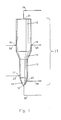
- FIG. 1 illustrates schematically the preferred embodiment of the sodium chloride crystallizer.
- the sodium chloride crystallizer is comprised of a vertically oriented crystallizer body (11) and the various inlets (16) through (19) and outlets (20) and (21) further described below.
- Crystallizer body (11) is comprised of upper segment (12), lower segment (13) and transition segment (14).
- Upper segment (12) has a greater cross-sectional area than that of lower segment (13).
- Transition segment (14) is provided to supply fluid communication between upper segment (12) and lower segment (13).
- crystallizer body (11) may have a second transition segment (15) below lower segment (13).
- Upper saturated MgCl2 brine inlet (16) and lower saturated MgCl2 brine inlet (17) are positioned at distinct vertical locations along crystallizer body (11), with the caveat that such locations have different cross-sectional areas.
- upper saturated MgCl2 brine inlet (16) is located in upper segment (12) and lower saturated MgCl2 brine inlet (17) is located in lower segment (13), it is possible, for example, to position upper saturated MgCl2 brine inlet (16) in transition segment (14) and lower saturated MgCl2 brine inlet (17) in optional second transition segment (15).
- Upper saturated MgCl2 brine inlet (16) and lower saturated MgCl2 brine inlet (17) are fed respectively by upper MgCl2 brine conduit (22) and lower MgCl2 brine conduit (23).
- Upper saturated NaCl brine inlet (18) and lower saturated NaCl brine inlet (19) are positioned along the crystallizer body (11), with the caveat that such locations have different cross-sectional areas.
- upper saturated NaCl brine inlet (18) is located in upper segment (12) and lower saturated NaCl brine inlet (19) is located in optional second transition segment (15), it is possible, for example to position upper saturated NaCl brine inlet (18) in transition segment (14) and lower saturated NaCl brine inlet (19) in lower segment (13).
- Upper saturated NaCl brine inlet (18) and lower saturated NaCl brine inlet (19) are fed respectively by upper NaCl brine conduit (25) and lower NaCl brine conduit (26).
- Lower outlet (20) is positioned in either the optional lower transition segment (15) or (particularly if lower transition segment (15) is not present) in lower segment (13).
- Lower outlet (20) is provided for the removal of a slurry of high purity (typically greater than 99,80% purity) sodium chloride. Also, a surprisingly high percentage of such sodium chloride will be in the form of hopper-shaped cubes. Conduit (28) is provided for further transport of the slurry. Typically, the sodium chloride slurry is transported to dehydration equipment (such as centrifuges) for removal of water from the slurry. Upper outlet (21) is provided for the removal of spent brine from the sodium chloride crystallizer.
- dehydration equipment such as centrifuges
- the crystallizer of the current invention may be comprised of additional segments of varying cross-sectional area, additional transition segments and additional inlets and outlets for the MgCl2 brines, NaCl brines, slurries, and crystallized sodium chloride.
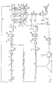
- the apparatus and process of the current invention may be further described with reference to FIG. 2.
- the apparatus of the current invention is comprised of one or more sodium chloride crystallizer body (11).
- Sodium crystallizer body (11) is illustrated in detail at FIG. 1 and described in detail above.
- Each sodium chloride crystallizer body (11) is fed by at least two saturated MgCl2 brine streams through upper saturated MgCl2 brine inlet (16) and lower saturated MgCl2 brine inlet (17).
- Inlets (16) and (17) are supplied via upper MgCl2 brine conduit (22) and lower MgCl2 brine conduit (23), respectively.
- Conduits (22) and (23) may be fed from one saturated MgCl2 brine conduit (24) (as shown in FIG. 2) or from separate saturated MgCl2 brine supply sources.
- Each sodium chloride crystallizer body (11) is also fed by at least two saturated NaCl brine streams through upper saturated NaCl brine inlet (18) and lower saturated NaCl brine inlet (19).
- Inlets (18) and (19) are supplied via upper NaCl brine conduit (25) and lower NaCl brine conduit (26), respectively.
- Conduits (25) and (26) may be fed from one saturated NaCl brine conduit (27) (as shown in FIG. 2) or from separate saturated NaCl brine supply sources.
- a slurry of sodium chloride crystals in brine is removed from crystallizer body (11) via lower outlet (20) and transported via conduit(s) (28) to a system suitable and adapted for removing brine from the sodium chloride crystals.
- An illustrative brine removal system shown in FIG. 2 is comprised of wash vessel (29), centrifuge (30) and dryer (31). The brine removed from wash vessel (29) and centrifuge (30) may be recycled back to crystallizer body (11) via conduits (32) and (33), and, eventually conduit (27). Spent brine is removed from crystallizer body (11) via upper outlet (21) and routed for further handling via conduits (34) and (35). The spent brine is preferably reconcentrated in MgCl2 for recycling to crystallizer (11).
- the spent brine is reconcentrated by a solar evaporation system substantially similar to the one illustrated at FIG. 2 and described below; however, the spent brine may be first removed to holding tank (36) prior to reconcentration.
- a solar evaporation system requires at least one solar pond.
- the solar evaporation system of the current application is comprised of first solar evaporation pond (37), second solar evaporation pond (38) and third solar evaporation pond (39).
- a three stage system to reconcentrate MgCl2 provides three batches of NaCl segregated by purity.
- the NaCl from the first solar pond has an approximately 99,0 to 99,7% purity
- the NaCl from the second solar pond has an approximately 98,5% to 99,0% purity
- the NaCl from the third solar pond has a purity of less than about 98,5%.
- the MgCl2 brine stream produced by the first solar pond comprises approximately 5,0 to 6,0 weight % MgCl2, the MgCl2 stream of the second pond approximately 6,0 to 7,0 weight % and the stream of the third pond 7,0 to 8,0 weight % MgCl2.
- the solar evaporation system may contain a spent brine holding tank (36) and a reconstituted storage tank (40).
- filter (41) and saturator (42) for solids removal and storage tank (43) for holding the reconstituted, filtered saturated MgCl2 brine prior to supply to crystallizer body (11) via conduits (24), (22) and (23).
- FIG. 2 One method of supplying NaCl saturated brine for supply to crystallizer body (11) is illustrated at FIG. 2.
- the method involves preparing "pickle brine” (brine which has undergone fractional crystallization in a so-called “lime pond” to remove a preponderance of the contaminant calcium sulfate) then storing it at the the proper sodium concentration in NaCl brine tank (44). Additionally, it may be desirable to provide filter (45) and saturator (46) for solids removal and storage tank (47) to hold the filtered sodium saturated brine prior to supply to crystallizer (11) via conduits (27), (26) and (25).
- the crystallizer, apparatus and process of the current disclosure produce high purity NaCl crystals. Additionally, a surprisingly high percentage of high purity NaCl crystals produced by the crystallizer, apparatus and/or process of the current invention are hopper-shaped cubes.
- This material balance was based on a daily production of 500 tons hopper-shaped NaCl as output (through one or more conduit(s) (28) from one or more crystallizer body (11).
- the composition of the NaCl product stream J (in slurry form) is detailed in Table 1. Approximately 50 to 80% of the NaCl crystals are hopper-shaped cubes.
- the hopper-shaped NaCl product may be further treated in wash vessel (29), centrifuge (30) and dryer (31) to produce dried, purified hopper-shaped salt granules.
- a substantially saturated NaCl brine (1020 gpm) of composition I is introduced into one or more crystallizer body (11) via conduits (25) and (26) to mix with a substantially saturated MgCl2 brine (870 gpm) of composition H which is introduced into crystallizer body (11) via conduits (22) and (23).
- the spent brine of composition A is removed via conduit (34) and transported via conduit (35).
- the spent brine is reconstituted and recycled to the one or more crystallizer body (11).
- Any reconstitution means which will provide an appropriate saturated MgCl2 brine for the crystallizer body (11) is acceptable in the current process.
- a solar evaporation system is employed for this Example 1.
- spent brine may be transported directly to first solar pond (37).
- the spent brine may be sent to spent brine holding tank (36) prior to introduction into first solar pond (37).
- First solar pond (37) is of sufficient size to allow concentration of the brine to composition C.
- First solar pond (37) produces approximately 146.842 tons per year of about 99,6% purity cubic NaCl having composition B, a brine of composition C and about 155 million gallons per year water of evaporation.
- Brine of composition C is further concentrated, which is accomplished in this example by use of secondary solar pond (38) and tertiary solar pond (39).
- the brine of composition C is transferred to secondary solar pond (38) having dimensions to produce a brine of composition E.
- Secondary solar pond (38) produces 108.216 tons per year of about 99,5% purity cubic NaCl having composition D, a brine of composition E and about 101 million gallons per year water of evaporation.
- the brine of composition E is transferred to tertiary solar pond (39) having dimensions to produce a brine composition G.
- Tertiary solar pond (39) produces 45.360 tons per year of mixed salts having composition F, a brine of composition G and about 25 million gallons per year water of evaporation.
- the mixed salts are predominantly chloride and sulfate salts of sodium, potassium and magnesium.
- the brine of composition G is typically sent to reconstituted storage tank (40) prior to treatment in filter (41) and saturator (42), then holding in storage tank (43) prior to use in crystallizer body (11). It should be noted that in addition to producing a saturated MgCl2 brine stream, the tertiary solar evaporation system of this Example produces NaCl of size and shape equivalent to that produced by conventional solar evaporation but segregated into three distinct purities.
- the saturated NaCl brine stream I is prepared by producing a so-called "pickle” brine in a "lime pond” (not shown) to remove the impurity calcium sulfate from the brine by fractional crystallization.
- the pickle brine of composition P may be stored in NaCl brine tank (44), treated in filter (45) and saturator (46), then stored in storage tank (47).
- the brine transferred from saturator (46) to storage tank (47) may have the composition I or it may have a composition so that when mixed with composition K in storage tank (47) the output of storage tank (47) will have the composition I.
- a portion of the "pickle brine" of composition P may be treated by solar evaporation processes similar to the evaporation process of solar ponds (37), (38) and (39).
- the portion of "pickle brine” is treated seriatum in solar ponds (50), (51) and (52) to produce brines of composition Q, R and S. Additionally, approximately 210.600 tons per year of "conventional" solar salt is produced from solar pond (50).
- a portion of the "conventional" solar salt crop may be dissolved in tank (48) to produce a substantially saturated NaCl solution of Composition N.
- Brine filter (49) may be used to remove suspended particulate contaminants.
- Brine of composition N may be mixed with brine of composition M removed from centrifuge (30) to provide co-mingled brine of composition L. This co-mingled brine may be used to wash the salt produced in crystallizer body (11) free of adhering mother liquor to produce a washed, purified NaCl of purity greater than 99,8%.
- a crystallizer similar to that illustrated in FIG. 1 was employed. With reference to FIG. 1, the crystallizer body had the following dimensions.
- the saturated MgCl2 brine streams and the saturated NaCl brine streams were introduced at locations as illustrated in FIG. 1.
- the operating data are provided at Table 2 for these separate runs through the above-described crystallizer.
- Runs A-C were conducted at ambient temperature and pressure.
- the NaCl product from Runs A-C, as determined by microscopic evaluation was approximately 75 wt.% hopper-shaped cubes and 25 wt.% simple cubes.
- This Example 3 demonstrates a "salting out” process generally of the type described in U.S. Patent 3 822 143.
- a funnel-shaped vertical reactor was employed. From top to bottom, the reactor comprised a 6,0" long x 18,0" I.D. top section, a 12" long x 18,0" I.D. x 3,25" I.D. transition section and a 24" long x 3,25 elutrating leg.
- Substantially saturated MgCl2 brine and substantially saturated NaCl were simultaneously fed through separate inputs into the base of the vertical reactor. The mixed brine was then circulated from the top of the reactor into the bottom of the elutrating leg. The time of the runs varied between 4 to 12 hours.
- the saturated MgCl2 brine input and the saturated NaCl input were each fed to the reactor at a rate of 0,066 gpm.
- the total flowrate to the reactor varied between 2,13 and 3,13 gpm.
- the circulation flowrate to the elutrating leg varied between 2,14 and 3,0 gpm.
- the NaCl product produced this salting out process as determined by microscopic evaluation was approximately 40 wt.% simple cubes, 60 wt.% agglomerated cubes and essentially no hopper-shaped cubes.
Landscapes
- Chemical & Material Sciences (AREA)
- Organic Chemistry (AREA)
- Engineering & Computer Science (AREA)
- Materials Engineering (AREA)
- Inorganic Chemistry (AREA)
- Crystallography & Structural Chemistry (AREA)
- Chemical Kinetics & Catalysis (AREA)
- Compounds Of Alkaline-Earth Elements, Aluminum Or Rare-Earth Metals (AREA)
- Crystals, And After-Treatments Of Crystals (AREA)
- Vaporization, Distillation, Condensation, Sublimation, And Cold Traps (AREA)
Applications Claiming Priority (2)
| Application Number | Priority Date | Filing Date | Title |
|---|---|---|---|
| US07/526,209 US5068092A (en) | 1990-05-21 | 1990-05-21 | Crystallizer, process and apparatus for producing sodium chloride crystals |
| US526209 | 1990-05-21 |
Publications (3)
| Publication Number | Publication Date |
|---|---|
| EP0458403A2 true EP0458403A2 (de) | 1991-11-27 |
| EP0458403A3 EP0458403A3 (en) | 1993-08-11 |
| EP0458403B1 EP0458403B1 (de) | 1995-07-19 |
Family
ID=24096394
Family Applications (1)
| Application Number | Title | Priority Date | Filing Date |
|---|---|---|---|
| EP91201184A Expired - Lifetime EP0458403B1 (de) | 1990-05-21 | 1991-05-16 | Verfahren zur Herstellung von Natriumchlorid |
Country Status (5)
| Country | Link |
|---|---|
| US (1) | US5068092A (de) |
| EP (1) | EP0458403B1 (de) |
| AU (1) | AU627977B2 (de) |
| DE (1) | DE69111301T2 (de) |
| ES (1) | ES2075930T3 (de) |
Cited By (2)
| Publication number | Priority date | Publication date | Assignee | Title |
|---|---|---|---|---|
| EP1184064A1 (de) * | 2000-08-28 | 2002-03-06 | Messo -Chemietechnik GmbH | Kristallpartikelreinigung durch Ultraschall |
| WO2011158260A1 (en) * | 2010-06-18 | 2011-12-22 | Egill Einarsson | Production of low sodium salt with balanced mineral content |
Families Citing this family (16)
| Publication number | Priority date | Publication date | Assignee | Title |
|---|---|---|---|---|
| CH690840A5 (de) * | 1996-07-17 | 2001-02-15 | Krebs Swiss Krebs & Co Ag | Salzreinigungsanlage. |
| US6193882B1 (en) | 1998-06-15 | 2001-02-27 | Rswc Inc. | Pressurized brining system |
| US8679291B2 (en) | 2007-03-13 | 2014-03-25 | Heartland Technology Partners Llc | Compact wastewater concentrator using waste heat |
| US10005678B2 (en) | 2007-03-13 | 2018-06-26 | Heartland Technology Partners Llc | Method of cleaning a compact wastewater concentrator |
| US8790496B2 (en) | 2007-03-13 | 2014-07-29 | Heartland Technology Partners Llc | Compact wastewater concentrator and pollutant scrubber |
| US8741100B2 (en) | 2007-03-13 | 2014-06-03 | Heartland Technology Partners Llc | Liquid concentrator |
| US8801897B2 (en) | 2007-03-13 | 2014-08-12 | Heartland Technology Partners Llc | Compact wastewater concentrator and contaminant scrubber |
| US7972391B2 (en) * | 2007-09-07 | 2011-07-05 | Mansur Abahusayn | Salt brine capillary crystallization |
| RU2530045C2 (ru) | 2009-02-12 | 2014-10-10 | Хартлэнд Текнолоджи Партнерс Ллк | Компактный концентратор сточных вод, работающий на отбросном тепле |
| US8721771B2 (en) | 2011-01-21 | 2014-05-13 | Heartland Technology Partners Llc | Condensation plume mitigation system for exhaust stacks |
| US9296624B2 (en) | 2011-10-11 | 2016-03-29 | Heartland Technology Partners Llc | Portable compact wastewater concentrator |
| US8808497B2 (en) | 2012-03-23 | 2014-08-19 | Heartland Technology Partners Llc | Fluid evaporator for an open fluid reservoir |
| US8741101B2 (en) | 2012-07-13 | 2014-06-03 | Heartland Technology Partners Llc | Liquid concentrator |
| US8585869B1 (en) | 2013-02-07 | 2013-11-19 | Heartland Technology Partners Llc | Multi-stage wastewater treatment system |
| US9199861B2 (en) | 2013-02-07 | 2015-12-01 | Heartland Technology Partners Llc | Wastewater processing systems for power plants and other industrial sources |
| WO2020243510A1 (en) | 2019-05-31 | 2020-12-03 | Heartland Technology Partners Llc | Harmful substance removal system and method |
Family Cites Families (20)
| Publication number | Priority date | Publication date | Assignee | Title |
|---|---|---|---|---|
| US2702121A (en) * | 1950-01-11 | 1955-02-15 | Public Ets | Methods of froth-flotation |
| US2968525A (en) * | 1958-06-09 | 1961-01-17 | Int Minerals & Chem Corp | Potash ore treatment |
| US3071450A (en) * | 1960-04-01 | 1963-01-01 | A Responsabilite Ltd Societe D | Method for the treatment of potassium ores |
| US3130016A (en) * | 1961-05-09 | 1964-04-21 | Pennsalt Chemicals Corp | Process for brine manufacture |
| US3832143A (en) * | 1969-03-17 | 1974-08-27 | Irving Trust Co | Crystallization of sodium chloride |
| US3852044A (en) * | 1969-11-13 | 1974-12-03 | Great Salt Lake Minerals | Recovery of substantially potassium-free hydrated magnesium chloride from contaminated aqueous solutions |
| US3895920A (en) * | 1970-09-03 | 1975-07-22 | Donald E Garrett | Method of producing coarse potash |
| US3743483A (en) * | 1971-05-28 | 1973-07-03 | Chemical Construction Corp | Crystallization of nacl from mgcl2 solution |
| US3772202A (en) * | 1971-06-28 | 1973-11-13 | Irving Trust Co | Moist road salt composition and process for making the same |
| US3833504A (en) * | 1971-06-28 | 1974-09-03 | Great Salt Lake Minerals | Moist road salt composition and process for making the same |
| IL50873A (en) * | 1976-11-09 | 1979-11-30 | Sadan A | Process for the production of potassium chloride and magnesium chloride from carnallite |
| US4119556A (en) * | 1977-06-01 | 1978-10-10 | Chubb Talbot A | Thermal energy storage material comprising mixtures of sodium, potassium and magnesium chlorides |
| US4386936A (en) * | 1979-02-01 | 1983-06-07 | Ppg Industries Canada Ltd. | Production of potassium chloride using pond crystallization |
| NO145376B (no) * | 1980-04-18 | 1981-11-30 | Norsk Hydro As | Fremgangsmaate for oppkonsentrering og rensing av mgcl2-lut |
| US4334885A (en) * | 1980-10-20 | 1982-06-15 | International Minerals & Chemical Corp. | Production of potassium chloride from langbeinite |
| FR2501181A1 (fr) * | 1981-03-05 | 1982-09-10 | Mdpa | Procede de traitement de minerais carnallitiques |
| JPS5882208A (ja) * | 1981-11-11 | 1983-05-17 | Furukawa Electric Co Ltd:The | 巻付式自己支持型光ケ−ブルの架設方法 |
| US4564367A (en) * | 1984-06-20 | 1986-01-14 | Diamond Crystal Salt Company | Solar salt crystallizer and process for producing salt |
| US4569676A (en) * | 1984-08-21 | 1986-02-11 | Cominco Ltd. | Separation and purification of salts in a non-convective solar pond |
| DE59003083D1 (de) * | 1990-01-12 | 1993-11-18 | Braunschweigische Masch Bau | Verfahren zur kontinuierlichen Herstellung von Kristall-Magma. |
-
1990
- 1990-05-21 US US07/526,209 patent/US5068092A/en not_active Expired - Lifetime
-
1991
- 1991-05-16 ES ES91201184T patent/ES2075930T3/es not_active Expired - Lifetime
- 1991-05-16 DE DE69111301T patent/DE69111301T2/de not_active Expired - Fee Related
- 1991-05-16 EP EP91201184A patent/EP0458403B1/de not_active Expired - Lifetime
- 1991-05-20 AU AU77230/91A patent/AU627977B2/en not_active Expired
Cited By (3)
| Publication number | Priority date | Publication date | Assignee | Title |
|---|---|---|---|---|
| EP1184064A1 (de) * | 2000-08-28 | 2002-03-06 | Messo -Chemietechnik GmbH | Kristallpartikelreinigung durch Ultraschall |
| WO2011158260A1 (en) * | 2010-06-18 | 2011-12-22 | Egill Einarsson | Production of low sodium salt with balanced mineral content |
| US8979948B2 (en) | 2010-06-18 | 2015-03-17 | Arctic Sea Minerals Ehf. | Production of low sodium salt with balanced mineral content |
Also Published As
| Publication number | Publication date |
|---|---|
| ES2075930T3 (es) | 1995-10-16 |
| EP0458403B1 (de) | 1995-07-19 |
| US5068092A (en) | 1991-11-26 |
| DE69111301T2 (de) | 1996-04-04 |
| AU627977B2 (en) | 1992-09-03 |
| AU7723091A (en) | 1991-11-21 |
| DE69111301D1 (de) | 1995-08-24 |
| EP0458403A3 (en) | 1993-08-11 |
Similar Documents
| Publication | Publication Date | Title |
|---|---|---|
| US5068092A (en) | Crystallizer, process and apparatus for producing sodium chloride crystals | |
| US6776972B2 (en) | Recovery of common salt and marine chemicals from brine | |
| US3655331A (en) | Production of sodium carbonate | |
| CA2464642C (en) | Recovery of sodium chloride and other salts from brine | |
| US3933977A (en) | Process for producing sodium carbonate | |
| CN102105399A (zh) | 氯化钠生产方法 | |
| AU2002212675A1 (en) | Recovery of sodium chloride and other salts from brine | |
| US5514359A (en) | Process for making anhydrous magnesium chloride | |
| US5447543A (en) | Process for crystallizing inorganic salts | |
| EP2490778A1 (de) | Verfahren zur kombinierten regeneration von löslichen salzen in rückständen eines industriellen prozesses | |
| AU2016376980B2 (en) | Method for the control of sulphate forming compounds in the preparation of potassium sulphate from potassium-containing ores at high ambient temperatures | |
| US3656892A (en) | Method of producing soda ash | |
| CA1101190A (en) | Method of separating salts from solution | |
| CN102762499A (zh) | 生产经自然纯化的盐产物的方法 | |
| US3690844A (en) | Recovery of sulfate-free hydrated magnesium chloride from sulfate-contaminated brines | |
| US20200231511A1 (en) | Carbon dioxide mediated recovery of potassium compounds from brines | |
| US2862788A (en) | Process for purifying impure solid-phase kainite | |
| US2759794A (en) | Purification of magnesium chloride solutions | |
| US20100143220A1 (en) | Cost-Effective Process for the Preparation of Solar Salt Having High Purity and Whiteness | |
| US3642455A (en) | Process for recovering low-sulfate bischofite | |
| JP3754953B2 (ja) | 製塩方法及び製塩装置 | |
| US5783159A (en) | Inorganic impurities removal in soda ash solutions with carbon | |
| CN108349743A (zh) | 在高环境温度下由含钾矿石生产硫酸钾的方法 | |
| JP2794063B2 (ja) | 結晶中への他成分導入方法およびこれを用いたミネラル塩の製造方法 | |
| SU829567A1 (ru) | Способ получени сульфата кали |
Legal Events
| Date | Code | Title | Description |
|---|---|---|---|
| PUAI | Public reference made under article 153(3) epc to a published international application that has entered the european phase |
Free format text: ORIGINAL CODE: 0009012 |
|
| AK | Designated contracting states |
Kind code of ref document: A2 Designated state(s): DE ES FR |
|
| PUAL | Search report despatched |
Free format text: ORIGINAL CODE: 0009013 |
|
| AK | Designated contracting states |
Kind code of ref document: A3 Designated state(s): DE ES FR |
|
| 17P | Request for examination filed |
Effective date: 19940113 |
|
| RAP1 | Party data changed (applicant data changed or rights of an application transferred) |
Owner name: AKZO NOBEL N.V. |
|
| 17Q | First examination report despatched |
Effective date: 19940722 |
|
| GRAA | (expected) grant |
Free format text: ORIGINAL CODE: 0009210 |
|
| AK | Designated contracting states |
Kind code of ref document: B1 Designated state(s): DE ES FR |
|
| REF | Corresponds to: |
Ref document number: 69111301 Country of ref document: DE Date of ref document: 19950824 |
|
| ET | Fr: translation filed | ||
| REG | Reference to a national code |
Ref country code: ES Ref legal event code: FG2A Ref document number: 2075930 Country of ref document: ES Kind code of ref document: T3 |
|
| PLBE | No opposition filed within time limit |
Free format text: ORIGINAL CODE: 0009261 |
|
| STAA | Information on the status of an ep patent application or granted ep patent |
Free format text: STATUS: NO OPPOSITION FILED WITHIN TIME LIMIT |
|
| 26N | No opposition filed | ||
| REG | Reference to a national code |
Ref country code: FR Ref legal event code: TP |
|
| REG | Reference to a national code |
Ref country code: ES Ref legal event code: PC2A |
|
| PGFP | Annual fee paid to national office [announced via postgrant information from national office to epo] |
Ref country code: DE Payment date: 20050630 Year of fee payment: 15 |
|
| PG25 | Lapsed in a contracting state [announced via postgrant information from national office to epo] |
Ref country code: DE Free format text: LAPSE BECAUSE OF NON-PAYMENT OF DUE FEES Effective date: 20061201 |
|
| PGFP | Annual fee paid to national office [announced via postgrant information from national office to epo] |
Ref country code: ES Payment date: 20100611 Year of fee payment: 20 Ref country code: FR Payment date: 20100525 Year of fee payment: 20 |
|
| REG | Reference to a national code |
Ref country code: ES Ref legal event code: FD2A Effective date: 20140826 |
|
| PG25 | Lapsed in a contracting state [announced via postgrant information from national office to epo] |
Ref country code: ES Free format text: LAPSE BECAUSE OF EXPIRATION OF PROTECTION Effective date: 20110517 |